element14 Community
element14 Community
    Register Log In
  • Site
  • Search
  • Log In Register
  • Community Hub
    Community Hub
    • What's New on element14
    • Feedback and Support
    • Benefits of Membership
    • Personal Blogs
    • Members Area
    • Achievement Levels
  • Learn
    Learn
    • Ask an Expert
    • eBooks
    • element14 presents
    • Learning Center
    • Tech Spotlight
    • STEM Academy
    • Webinars, Training and Events
    • Learning Groups
  • Technologies
    Technologies
    • 3D Printing
    • FPGA
    • Industrial Automation
    • Internet of Things
    • Power & Energy
    • Sensors
    • Technology Groups
  • Challenges & Projects
    Challenges & Projects
    • Design Challenges
    • element14 presents Projects
    • Project14
    • Arduino Projects
    • Raspberry Pi Projects
    • Project Groups
  • Products
    Products
    • Arduino
    • Avnet Boards Community
    • Dev Tools
    • Manufacturers
    • Multicomp Pro
    • Product Groups
    • Raspberry Pi
    • RoadTests & Reviews
  • Store
    Store
    • Visit Your Store
    • Choose another store...
      • Europe
      •  Austria (German)
      •  Belgium (Dutch, French)
      •  Bulgaria (Bulgarian)
      •  Czech Republic (Czech)
      •  Denmark (Danish)
      •  Estonia (Estonian)
      •  Finland (Finnish)
      •  France (French)
      •  Germany (German)
      •  Hungary (Hungarian)
      •  Ireland
      •  Israel
      •  Italy (Italian)
      •  Latvia (Latvian)
      •  
      •  Lithuania (Lithuanian)
      •  Netherlands (Dutch)
      •  Norway (Norwegian)
      •  Poland (Polish)
      •  Portugal (Portuguese)
      •  Romania (Romanian)
      •  Russia (Russian)
      •  Slovakia (Slovak)
      •  Slovenia (Slovenian)
      •  Spain (Spanish)
      •  Sweden (Swedish)
      •  Switzerland(German, French)
      •  Turkey (Turkish)
      •  United Kingdom
      • Asia Pacific
      •  Australia
      •  China
      •  Hong Kong
      •  India
      •  Korea (Korean)
      •  Malaysia
      •  New Zealand
      •  Philippines
      •  Singapore
      •  Taiwan
      •  Thailand (Thai)
      • Americas
      •  Brazil (Portuguese)
      •  Canada
      •  Mexico (Spanish)
      •  United States
      Can't find the country/region you're looking for? Visit our export site or find a local distributor.
  • Translate
  • Profile
  • Settings
Raspberry Pi
  • Products
  • More
Raspberry Pi
Raspberry Pi Forum Want to create a capacitance proximity/touch sensor with a RP2040 Pico board using PIO
  • Blog
  • Forum
  • Documents
  • Quiz
  • Events
  • Polls
  • Files
  • Members
  • Mentions
  • Sub-Groups
  • Tags
  • More
  • Cancel
  • New
Join Raspberry Pi to participate - click to join for free!
Featured Articles
Announcing Pi
Technical Specifications
Raspberry Pi FAQs
Win a Pi
Raspberry Pi Wishlist
Actions
  • Share
  • More
  • Cancel
Forum Thread Details
  • State Not Answered
  • Replies 36 replies
  • Subscribers 661 subscribers
  • Views 11291 views
  • Users 0 members are here
  • proximity_sensors
  • rp2040
  • PIO
  • capacitive
Related

Want to create a capacitance proximity/touch sensor with a RP2040 Pico board using PIO

BigG
BigG over 3 years ago

There is nothing quite like solving a problem to help develop new skills. In this case I have found a library solution to what I want to achieve but it is not RP2040 compatible and of course it does not use PIO, which is the skill I am trying to acquire.

Having seen other members deliver some great PIO related projects, I thought this would be a great opportunity to build a solution together while helping me, and hopefully others, grasp how to develop PIO code from scratch.

Basically I want to create a capacitance touch or proximity sensor using a Raspberry Pi Pico (RP2040) board.

There is an Arduino library that can do this: https://github.com/PaulStoffregen/CapacitiveSensor

But it is not RP2040 compatible: https://github.com/PaulStoffregen/CapacitiveSensor/issues/42

Having reviewed this library, it appears on face value to be well suited to use PIO. Only, I don't know how to start.

As far as I can make out, there is only one function to apply PIO... but maybe others see things differently. I'm keen to learn more.

// Private Methods /////////////////////////////////////////////////////////////
// Functions only available to other functions in this library

int CapacitiveSensor::SenseOneCycle(void)
{
    noInterrupts();
	DIRECT_WRITE_LOW(sReg, sBit);	// sendPin Register low
	DIRECT_MODE_INPUT(rReg, rBit);	// receivePin to input (pullups are off)
	DIRECT_MODE_OUTPUT(rReg, rBit); // receivePin to OUTPUT
	DIRECT_WRITE_LOW(rReg, rBit);	// pin is now LOW AND OUTPUT
	delayMicroseconds(10);
	DIRECT_MODE_INPUT(rReg, rBit);	// receivePin to input (pullups are off)
	DIRECT_WRITE_HIGH(sReg, sBit);	// sendPin High
    interrupts();

	while ( !DIRECT_READ(rReg, rBit) && (total < CS_Timeout_Millis) ) {  // while receive pin is LOW AND total is positive value
		total++;
	}
	//Serial.print("SenseOneCycle(1): ");
	//Serial.println(total);

	if (total > CS_Timeout_Millis) {
		return -2;         //  total variable over timeout
	}

	// set receive pin HIGH briefly to charge up fully - because the while loop above will exit when pin is ~ 2.5V
    noInterrupts();
	DIRECT_WRITE_HIGH(rReg, rBit);
	DIRECT_MODE_OUTPUT(rReg, rBit);  // receivePin to OUTPUT - pin is now HIGH AND OUTPUT
	DIRECT_WRITE_HIGH(rReg, rBit);
	DIRECT_MODE_INPUT(rReg, rBit);	// receivePin to INPUT (pullup is off)
	DIRECT_WRITE_LOW(sReg, sBit);	// sendPin LOW
    interrupts();

#ifdef FIVE_VOLT_TOLERANCE_WORKAROUND
	DIRECT_MODE_OUTPUT(rReg, rBit);
	DIRECT_WRITE_LOW(rReg, rBit);
	delayMicroseconds(10);
	DIRECT_MODE_INPUT(rReg, rBit);	// receivePin to INPUT (pullup is off)
#else
	while ( DIRECT_READ(rReg, rBit) && (total < CS_Timeout_Millis) ) {  // while receive pin is HIGH  AND total is less than timeout
		total++;
	}
#endif
	//Serial.print("SenseOneCycle(2): ");
	//Serial.println(total);

	if (total >= CS_Timeout_Millis) {
		return -2;     // total variable over timeout
	} else {
		return 1;
	}
}

  • Sign in to reply
  • Cancel
  • BigG
    0 BigG over 3 years ago

    We all have to start somewhere and the usual place to start is with a "hello world" type example. This sets the platform to build upon and for me it is right at the very bottom... hence here is my take (from an Arduino c++ perspective) on the hello_pio example found on GitHub: https://github.com/raspberrypi/pico-examples/tree/master/pio/hello_pio

    Now I am looking at this very basic example and wondering, which comes first (the chicken or the egg?)... namely the PIO routine or the sketch. It's not immediately obvious. Maybe others can give guidance here.

    Anyhow, I thought to start with the PIO file.

    Here I see we need to give our instruction set a name

    .program hello

    Then it looks like we need to "pull" in some data for the PIO to use, that is, load a 32-bit word from the TX FIFO into the Output Shift Register (OSR).

    pull

    Then it looks like we need to do something and in this case as it is using this "out" command this means (according to the documentation) we will be shifting bits out of the Output Shift Register (OSR), and writing those bits to a Destination (and in this case I think the destination is "pins") and the value 1 is related to PINDIRS which determines whether that pin is input or output. Then it seems that we return back to the start as defined by the name "loop" and wait for the next "pull".

    out pins, 1
    jmp loop

    And this is where I get stumped. The PIO code seems to include an initialisation function. It is hard to determine if this is standard, as in the same function can be used for any example, or it is example specific.

    % c-sdk {
    static inline void hello_program_init(PIO pio, uint sm, uint offset, uint pin) {
        pio_sm_config c = hello_program_get_default_config(offset);
    
        // Map the state machine's OUT pin group to one pin, namely the `pin`
        // parameter to this function.
        sm_config_set_out_pins(&c, pin, 1);
        // Set this pin's GPIO function (connect PIO to the pad)
        pio_gpio_init(pio, pin);
        // Set the pin direction to output at the PIO
        pio_sm_set_consecutive_pindirs(pio, sm, pin, 1, true);
    
        // Load our configuration, and jump to the start of the program
        pio_sm_init(pio, sm, offset, &c);
        // Set the state machine running
        pio_sm_set_enabled(pio, sm, true);
    }
    %}

    Then we get to the application code itself. Even though I don't fully understand the PIO side fully, it was pretty easy to convert the c code for Arduino. I even added a few mods myself:

    #include "hardware/pio.h"
    #include "hardware/clocks.h"
    
    #include "blink.pio.h"
    
    #define PICO_DEFAULT_LED_PIN    12
    
    // Choose which PIO instance to use (there are two instances)
    PIO pio = pio0;
    
    // Find a free state machine on our chosen PIO (erroring if there are
    // none). Configure it to run our program, and start it, using the
    // helper function we included in our .pio file.
    unsigned int sm = 0;
    
    void setup() {
      // put your setup code here, to run once:
      Serial.begin(115200);
      while(!Serial) {;;}
    
      Serial.println("\r\nPIO Hello World Blink Example");
        
      // Our assembled program needs to be loaded into this PIO's instruction
      // memory. This SDK function will find a location (offset) in the
      // instruction memory where there is enough space for our program. We need
      // to remember this location!
      unsigned int offset = pio_add_program(pio, &hello_program);
      Serial.println("Assembled program loaded into memory with offset set at "+String(offset));
      
      sm = pio_claim_unused_sm(pio, true);    // An error will be generated if none available
      
      Serial.println("State machine "+String(sm)+ " was claimed for our chosen PIO");
      
      hello_program_init(pio, sm, offset, PICO_DEFAULT_LED_PIN);
      Serial.println("Hello World Blink PIO instance now initialised");
      
    }
    
    void loop() {
      // The state machine is now running. Any value we push to its TX FIFO will
      // appear on the LED pin.
      // Blink
      pio_sm_put_blocking(pio, sm, 1);
      sleep_ms(500);
      // Blonk
      pio_sm_put_blocking(pio, sm, 0);
      sleep_ms(500);
      // Blink
      pio_sm_put_blocking(pio, sm, 1);
      sleep_ms(1500);
      // Blonk
      pio_sm_put_blocking(pio, sm, 0);
      sleep_ms(500);
    }

    Of course, I learnt through other element14 posts that you have to convert your PIO code and a simple way to do this is use this online tool: https://wokwi.com/tools/pioasm

    Once done you can compile and upload your code.

    Of course one example does not give all the answers or offer up a solution suited for my design to create a capacitive sensor.

    As such I moved onto the pio_blink example. This PIO code is considerably more complicated using jmp, mov and set commands as well as a .wrap directive. Thankfully "pull block" is intuitive enough in that the block parameter means it will block until some data has been received as compared to the noblock parameter or not using a parameter at all.

    .program blink
    pull block
    out y, 32
    .wrap_target
    mov x, y
    set pins, 1 ; Turn LED on
    lp1:
    jmp x-- lp1 ; Delay for (x + 1) cycles, x is a 32 bit number
    mov x, y
    set pins, 0 ; Turn LED off
    lp2:
    jmp x-- lp2 ; Delay for the same number of cycles again
    .wrap ; Blink forever!

    I get a sense this is going to take awhile...

    • Cancel
    • Vote Up +1 Vote Down
    • Sign in to reply
    • Verify Answer
    • Cancel
  • scottiebabe
    0 scottiebabe over 3 years ago

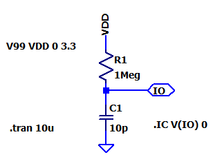
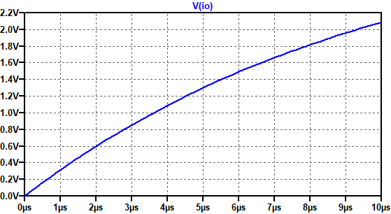
    Hello, I'm a hardware gal and can't make heads or tails of that library. I'm not sure why you need 2 GPIO pins. I assume the author is trying to measure the charge time of the capacitance seen on a GPIO pin. So something like this,

    image image

    So presumably, the GPIO pin can output low to reset the effective capacitance on the pin. Then go Hi-Z and measure the time taken for the capacitance to charge to a VIH threshold.

    I'm not sure I know the PIO module well enough to write a how-to guide, but I am happy to answer questions to the best of my knowledge, because I think the PIO module is pretty neat.

    • Cancel
    • Vote Up +3 Vote Down
    • Sign in to reply
    • Verify Answer
    • Cancel
  • scottiebabe
    0 scottiebabe over 3 years ago in reply to BigG

    I think you are doing all the right things by starting to experiment :) I have only used the PIO in uPython so there is a very slight difference in how a statemachine is configured but I don't that is too important.

    To the best of my knowledge you are 100% correct about the pull instruction, it used to load the Output Shift Register and reset the shift counter. A blocking pull loads an element from the TX fifo into the OSR, if the fifo is empty it stalls until an element is available. A non-blocking pull will load the OSR from the TX-fifo if its not empty otherwise it will load the OSR with the value in the x-scratch register.

    For the out instruction the second numeric operand is the shift count. So in your example program you were writing the LSB of the OSR to your assigned pin. Off the top of my head I'm not sure what happens when the shift count doesn't match the pin count.

    • Cancel
    • Vote Up +1 Vote Down
    • Sign in to reply
    • Verify Answer
    • Cancel
  • BigG
    0 BigG over 3 years ago in reply to scottiebabe

    Thanks for the comment.

    scottiebabe said:
    I'm not sure why you need 2 GPIO pins.

    I believe one GPIO is used as an output pin (rather than use VDD as per your diagram) and the other GPIO is used to measure the charge time... I see you figured that out anyway.

    I think parts of the SenseOneCycle function, which I am trying to change to PIO can be easy to convert, like setting pins to input or output and then setting high or low.

    Parts I'm not sure about are things like...

    How to covert delayMicroseconds(10); to PIO code if CPU clock speed is unknown. Maybe in this application 10 microseconds is not that critical and if so what should I have in PIO.

    Then I am assuming that this part of the code probably won't work that well in PIO as involves Math. If so then probably the PIO code part might need to be split into two or more parts etc.

    while ( !DIRECT_READ(rReg, rBit) && (total < CS_Timeout_Millis) ) {  // while receive pin is LOW AND total is positive value
            total++;
    }

    • Cancel
    • Vote Up +1 Vote Down
    • Sign in to reply
    • Verify Answer
    • Cancel
  • scottiebabe
    0 scottiebabe over 3 years ago in reply to BigG

    In python I'm used to just specify the frequency I want and letting the libraries set the statemachine clock divider values for me.

    smHsync = rp2.StateMachine(0, hsyncpio, freq=25_000_000,  set_base=Pin(16))
    smVsync = rp2.StateMachine(1, vsyncpio, freq=25_000_000,  set_base=Pin(17))

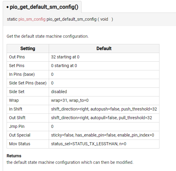
    By default the statemachine should run at the Sysclock frequency and I don't believe the config function alters the clock divider

    image 

    So you would need a busy loop that takes 10us * sysclock (typ 125MHz) = 1250 cycles.

    I have been thinking about how to make a state machine to scan a 4x4 keypad, and will agree trying to do math isn't easy...

    Since there is no add instruction, to count we would have to decrement a scratch register which could be initialized the the timeout count.

    And later convert to an equivalent positive count. If we omit the timeout and begin counting down from -1 (0xFFFF...) then the positive equivalent is just the bitwise complement.

    • Cancel
    • Vote Up +2 Vote Down
    • Sign in to reply
    • Verify Answer
    • Cancel
  • BigG
    0 BigG over 3 years ago in reply to BigG
    BigG said:
    I think parts of the SenseOneCycle function, which I am trying to change to PIO can be easy to convert, like setting pins to input or output and then setting high or low.

    LOL.

    Even this part is proving quite tricky. From what I've gathered you have to use the shift register to set multiple pins as input or output and that this is referenced based on the pin you select.

    What is not clear at all is whether an input pin can be changed to an output pin and this back to input again.

    Would love to know...

    • Cancel
    • Vote Up +1 Vote Down
    • Sign in to reply
    • Verify Answer
    • Cancel
  • scottiebabe
    0 scottiebabe over 3 years ago in reply to BigG

    This I do have answer with confidence, yes you can absolutely go back and forth between inputs and outputs, I used that feature to tri-state multiplex my fairy lights AngelSparkles. Writing a 1 to the pindirs register sets the pin to be an output.

    set(pindirs, 0b011)

    If you are planning to use 2 gpio pins, you could configure the tx pin to be a sideset pin and then assign its output state at every instruction with the 

    .side(val) then you don't have to try and bit twiddle and an input and output pin together.

    • Cancel
    • Vote Up +2 Vote Down
    • Sign in to reply
    • Verify Answer
    • Cancel
  • BigG
    0 BigG over 3 years ago in reply to scottiebabe

    Ah brilliant. Thanks for this explanation.

    I have just discovered a very useful video on YouTube which is helping a bit too.

    You don't have permission to edit metadata of this video.
    Edit media
    x
    image
    Upload Preview
    image

    • Cancel
    • Vote Up +4 Vote Down
    • Sign in to reply
    • Verify Answer
    • Cancel
  • scottiebabe
    0 scottiebabe over 3 years ago in reply to BigG

    That video looks incredible! Great find!

    • Cancel
    • Vote Up +1 Vote Down
    • Sign in to reply
    • Verify Answer
    • Cancel
  • scottiebabe
    0 scottiebabe over 3 years ago in reply to BigG

    I just came across this author who has shared a number of PIO examples with fairly detailed comments and explanations

    https://github.com/GitJer/Some_RPI-Pico_stuff/blob/main/HCSR04/HCSR04.pio   

    Not exactly the same problem, but similar ideas I think

    • Cancel
    • Vote Up +1 Vote Down
    • Sign in to reply
    • Verify Answer
    • Cancel
>
element14 Community

element14 is the first online community specifically for engineers. Connect with your peers and get expert answers to your questions.

  • Members
  • Learn
  • Technologies
  • Challenges & Projects
  • Products
  • Store
  • About Us
  • Feedback & Support
  • FAQs
  • Terms of Use
  • Privacy Policy
  • Legal and Copyright Notices
  • Sitemap
  • Cookies

An Avnet Company © 2025 Premier Farnell Limited. All Rights Reserved.

Premier Farnell Ltd, registered in England and Wales (no 00876412), registered office: Farnell House, Forge Lane, Leeds LS12 2NE.

ICP 备案号 10220084.

Follow element14

  • X
  • Facebook
  • linkedin
  • YouTube