element14 Community
element14 Community
    Register Log In
  • Site
  • Search
  • Log In Register
  • Community Hub
    Community Hub
    • What's New on element14
    • Feedback and Support
    • Benefits of Membership
    • Personal Blogs
    • Members Area
    • Achievement Levels
  • Learn
    Learn
    • Ask an Expert
    • eBooks
    • element14 presents
    • Learning Center
    • Tech Spotlight
    • STEM Academy
    • Webinars, Training and Events
    • Learning Groups
  • Technologies
    Technologies
    • 3D Printing
    • FPGA
    • Industrial Automation
    • Internet of Things
    • Power & Energy
    • Sensors
    • Technology Groups
  • Challenges & Projects
    Challenges & Projects
    • Design Challenges
    • element14 presents Projects
    • Project14
    • Arduino Projects
    • Raspberry Pi Projects
    • Project Groups
  • Products
    Products
    • Arduino
    • Avnet Boards Community
    • Dev Tools
    • Manufacturers
    • Multicomp Pro
    • Product Groups
    • Raspberry Pi
    • RoadTests & Reviews
  • Store
    Store
    • Visit Your Store
    • Choose another store...
      • Europe
      •  Austria (German)
      •  Belgium (Dutch, French)
      •  Bulgaria (Bulgarian)
      •  Czech Republic (Czech)
      •  Denmark (Danish)
      •  Estonia (Estonian)
      •  Finland (Finnish)
      •  France (French)
      •  Germany (German)
      •  Hungary (Hungarian)
      •  Ireland
      •  Israel
      •  Italy (Italian)
      •  Latvia (Latvian)
      •  
      •  Lithuania (Lithuanian)
      •  Netherlands (Dutch)
      •  Norway (Norwegian)
      •  Poland (Polish)
      •  Portugal (Portuguese)
      •  Romania (Romanian)
      •  Russia (Russian)
      •  Slovakia (Slovak)
      •  Slovenia (Slovenian)
      •  Spain (Spanish)
      •  Sweden (Swedish)
      •  Switzerland(German, French)
      •  Turkey (Turkish)
      •  United Kingdom
      • Asia Pacific
      •  Australia
      •  China
      •  Hong Kong
      •  India
      •  Korea (Korean)
      •  Malaysia
      •  New Zealand
      •  Philippines
      •  Singapore
      •  Taiwan
      •  Thailand (Thai)
      • Americas
      •  Brazil (Portuguese)
      •  Canada
      •  Mexico (Spanish)
      •  United States
      Can't find the country/region you're looking for? Visit our export site or find a local distributor.
  • Translate
  • Profile
  • Settings
Raspberry Pi
  • Products
  • More
Raspberry Pi
Raspberry Pi Forum RP2040 PIO/SPI MORE THAN 32 BITS
  • Blog
  • Forum
  • Documents
  • Quiz
  • Events
  • Polls
  • Files
  • Members
  • Mentions
  • Sub-Groups
  • Tags
  • More
  • Cancel
  • New
Join Raspberry Pi to participate - click to join for free!
Featured Articles
Announcing Pi
Technical Specifications
Raspberry Pi FAQs
Win a Pi
Raspberry Pi Wishlist
Actions
  • Share
  • More
  • Cancel
Forum Thread Details
  • State Not Answered
  • Replies 10 replies
  • Subscribers 662 subscribers
  • Views 3397 views
  • Users 0 members are here
  • spi
  • rp2040
  • swd
  • PIO
Related

RP2040 PIO/SPI MORE THAN 32 BITS

gabofienco
gabofienco over 2 years ago

Hello,

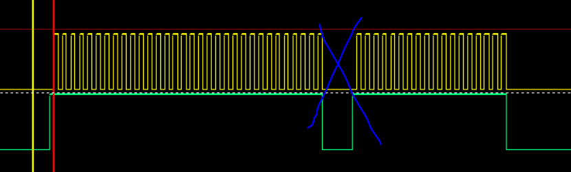
I am working with RP2040 using the PICOPROBE code with some modifications, do you have any idea how to send more than 32 consecutive bits, setting values with the clock is ok, more than 32 periods if I want to, but on data it limits to a uint32_t.... and if I send another frame it generates an undesired delay:

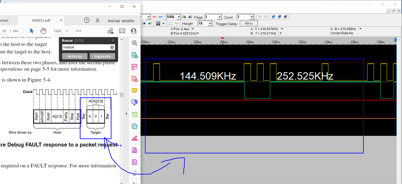
yellow CLOCK, green MOSI.

image

I am trying to generate the SWD initi sequence on code, it will be good to send at least 200 clock pulses with its respective Data.

Thanks.

  • Sign in to reply
  • Cancel
  • BigG
    0 BigG over 2 years ago

    Have you tried using both X and Y registers.

    • Cancel
    • Vote Up 0 Vote Down
    • Sign in to reply
    • Verify Answer
    • Cancel
  • scottiebabe
    0 scottiebabe over 2 years ago

    Yes, you can write a PIO routine to output n-bit SPI. Are you using this PIO routine: https://github.com/raspberrypi/picoprobe/blob/master/src/probe.pio 

    It gets complicated having to reload the OSR every 32-bits.  You could use the autopull feature, but then it gets complicated syncronizing on the first FIFO write which sets the bit count.

    If you only need n-bit SPI to clock 0's, you could just write another pio routine clock out N zeros.

    • Cancel
    • Vote Up +1 Vote Down
    • Sign in to reply
    • Verify Answer
    • Cancel
  • gabofienco
    0 gabofienco over 2 years ago in reply to scottiebabe

    Thanks for your answer, Yes I am having some issues reloading the OSR and sincronizing it.

    that is the PIO file I am using, I am trying to emulate the SWD init sequence, I think that the main problem I don't get any response from the other rp2040 is because of the delay on data every 32btis, I don't know if that makes sense to any of you ?

    Thanks again.

    • Cancel
    • Vote Up +1 Vote Down
    • Sign in to reply
    • Verify Answer
    • Cancel
  • shabaz
    0 shabaz over 2 years ago in reply to gabofienco

    Hi,

    Regarding: "I think that the main problem I don't get any response from the other rp2040"

    I'm confused - the PicoProbe code is already designed to work with RP2040, and has been used in that way by hundreds/thousands of people surely? Does it not already use the SWD sequence you are attempting, or am I misunderstanding it?

    • Cancel
    • Vote Up 0 Vote Down
    • Sign in to reply
    • Verify Answer
    • Cancel
  • gabofienco
    0 gabofienco over 2 years ago in reply to shabaz

    Yes, but I am trying to move a data that is already stored on another flash address from rp2040_1 to the SWD pins from rp2040_2, I don't use the USB to download the data to rp2040_2 and letting it do all the syncronization that way (on my board I don't have access to those pins, is not a raspberry pi pico board is my own board).

    So, I am having problems trying to get the SWD init, I think that even with the delay between spi frames it should work as PICOPROBE seems to make it work that way already.

    That is how it has to work for the hardware I already have on the boards, does it make any sense to you?

    I had checked so much info about the sequence to init SWD that I don't that I am sending wrong bits.

    • Cancel
    • Vote Up 0 Vote Down
    • Sign in to reply
    • Verify Answer
    • Cancel
  • shabaz
    0 shabaz over 2 years ago in reply to gabofienco

    Hi,

    The PicoProbe USB code portion is likely decoupled from the SWD code (I've not checked, but it should be), so if you're not using USB in your version of code, it should make no difference.

    As you yourself say, since PicoProbe already functions on the SWD interface side, then it should work with your version of code. The delay may be a red herring, you can prove it to yourself by examining with a 'scope if possible (or a logic analyzer), and comparing the normal PicoProbe with your version, to see where the discrepancy is, if source code examination isn't helping so far.

    It makes no sense that it would not work in your code if the normal PicoProbe works (have you tested the normal PicoProbe code with a normal Pi Pico with your RP2040 target, just to be 1000% sure that you don't have an issue elsewhere in the system?).

    • Cancel
    • Vote Up +2 Vote Down
    • Sign in to reply
    • Verify Answer
    • Cancel
  • scottiebabe
    0 scottiebabe over 2 years ago in reply to gabofienco

    Technically with that code you should be able to get a constant clock output for n-bits:

    static inline void probe_write_bits(uint bit_count, uint8_t data_byte) {
        DEBUG_PINS_SET(probe_timing, DBG_PIN_WRITE);
        pio_sm_put_blocking(pio0, PROBE_SM, bit_count - 1);
        pio_sm_put_blocking(pio0, PROBE_SM, data_byte);
        DEBUG_PINS_SET(probe_timing, DBG_PIN_WRITE_WAIT);
        picoprobe_dump("Write %d bits 0x%x\n", bit_count, data_byte);
        // Wait for pio to push garbage to rx fifo so we know it has finished sending
        pio_sm_get_blocking(pio0, PROBE_SM);
        DEBUG_PINS_CLR(probe_timing, DBG_PIN_WRITE_WAIT);
        DEBUG_PINS_CLR(probe_timing, DBG_PIN_WRITE);
    }

    I believe the output data should just be zero's after the 8-bit data byte is shifted out.

    As shabaz mentions the picoprobe does work, later I will try to capture some SWD traffic and hopefully decode it with sigrok:

    image

    I really don't know much about SWD, so it's a good excuse to take a peak.

    • Cancel
    • Vote Up +1 Vote Down
    • Sign in to reply
    • Verify Answer
    • Cancel
  • shabaz
    0 shabaz over 2 years ago in reply to scottiebabe

    The OP could also extend the print statement (picoprobe_dump) (EDIT: just noticed, looks like it already displays them in that snippet) to display the individual bits or bytes, to be 1000% sure that the custom code is behaving the same way. I think SWD is an encoding of JTAG, but I've never examined with a 'scope/LA either, so it will be good to see it : ) 

    • Cancel
    • Vote Up +1 Vote Down
    • Sign in to reply
    • Verify Answer
    • Cancel
  • gabofienco
    0 gabofienco over 2 years ago in reply to scottiebabe

    Hello thanks,

    I finally manage to get the picoprobe local server with openocd to compare the frames, so they don't need to be consecutive bits, they can have a delay... now my question is solve about the consecutive bits, if you modify that function you will have a limit of 32bits (pio_sm_put_blocking)... seems that the SM can store that.. and the clock is not limit to 32clock counts because that is a number for the loop that is why is greater than 32 obviously, while the SWdio is not a loop.. is the bit itself.

    Anyway, now I think the problem is the sequence I am sending just to get the SWD connection, not even sending the firmware yet hehe.

    The second MCU is answering me with a fault state... it is getting hard without a protocol analyzer I think.

    image

    But I think that is another topic now.

    it would had been nice to find a way to set more than 32 bits, but now I know it is not needed.

    Thanks.

    • Cancel
    • Vote Up 0 Vote Down
    • Sign in to reply
    • Verify Answer
    • Cancel
  • gabofienco
    0 gabofienco over 2 years ago in reply to shabaz

    Taking your idea as a reference I am trying to reply every frame that the picoprobe does, but without a protocol analyzer is getting hard to know which are send by mcu_A or which are replies from mcu_B, I really think the protocol documentation needs examples hehe.. I am using some info from another cortexM0+ MCUs, but at least I made 1 little step now.

    • Cancel
    • Vote Up 0 Vote Down
    • Sign in to reply
    • Verify Answer
    • Cancel
element14 Community

element14 is the first online community specifically for engineers. Connect with your peers and get expert answers to your questions.

  • Members
  • Learn
  • Technologies
  • Challenges & Projects
  • Products
  • Store
  • About Us
  • Feedback & Support
  • FAQs
  • Terms of Use
  • Privacy Policy
  • Legal and Copyright Notices
  • Sitemap
  • Cookies

An Avnet Company © 2025 Premier Farnell Limited. All Rights Reserved.

Premier Farnell Ltd, registered in England and Wales (no 00876412), registered office: Farnell House, Forge Lane, Leeds LS12 2NE.

ICP 备案号 10220084.

Follow element14

  • X
  • Facebook
  • linkedin
  • YouTube