element14 Community
element14 Community
    Register Log In
  • Site
  • Search
  • Log In Register
  • About Us
  • Community Hub
    Community Hub
    • What's New on element14
    • Feedback and Support
    • Benefits of Membership
    • Personal Blogs
    • Members Area
    • Achievement Levels
  • Learn
    Learn
    • Ask an Expert
    • eBooks
    • element14 presents
    • Learning Center
    • Tech Spotlight
    • STEM Academy
    • Webinars, Training and Events
    • Learning Groups
  • Technologies
    Technologies
    • 3D Printing
    • FPGA
    • Industrial Automation
    • Internet of Things
    • Power & Energy
    • Sensors
    • Technology Groups
  • Challenges & Projects
    Challenges & Projects
    • Design Challenges
    • element14 presents Projects
    • Project14
    • Arduino Projects
    • Raspberry Pi Projects
    • Project Groups
  • Products
    Products
    • Arduino
    • Avnet Boards Community
    • Dev Tools
    • Manufacturers
    • Multicomp Pro
    • Product Groups
    • Raspberry Pi
    • RoadTests & Reviews
  • Store
    Store
    • Visit Your Store
    • Choose another store...
      • Europe
      •  Austria (German)
      •  Belgium (Dutch, French)
      •  Bulgaria (Bulgarian)
      •  Czech Republic (Czech)
      •  Denmark (Danish)
      •  Estonia (Estonian)
      •  Finland (Finnish)
      •  France (French)
      •  Germany (German)
      •  Hungary (Hungarian)
      •  Ireland
      •  Israel
      •  Italy (Italian)
      •  Latvia (Latvian)
      •  
      •  Lithuania (Lithuanian)
      •  Netherlands (Dutch)
      •  Norway (Norwegian)
      •  Poland (Polish)
      •  Portugal (Portuguese)
      •  Romania (Romanian)
      •  Russia (Russian)
      •  Slovakia (Slovak)
      •  Slovenia (Slovenian)
      •  Spain (Spanish)
      •  Sweden (Swedish)
      •  Switzerland(German, French)
      •  Turkey (Turkish)
      •  United Kingdom
      • Asia Pacific
      •  Australia
      •  China
      •  Hong Kong
      •  India
      •  Korea (Korean)
      •  Malaysia
      •  New Zealand
      •  Philippines
      •  Singapore
      •  Taiwan
      •  Thailand (Thai)
      • Americas
      •  Brazil (Portuguese)
      •  Canada
      •  Mexico (Spanish)
      •  United States
      Can't find the country/region you're looking for? Visit our export site or find a local distributor.
  • Translate
  • Profile
  • Settings
Raspberry Pi
  • Products
  • More
Raspberry Pi
Raspberry Pi Forum 24v COB rgb 840 strip controled by Raspberry Pi
  • Blog
  • Forum
  • Documents
  • Quiz
  • Events
  • Polls
  • Files
  • Members
  • Mentions
  • Sub-Groups
  • Tags
  • More
  • Cancel
  • New
Join Raspberry Pi to participate - click to join for free!
Featured Articles
Announcing Pi
Technical Specifications
Raspberry Pi FAQs
Win a Pi
Raspberry Pi Wishlist
Actions
  • Share
  • More
  • Cancel
Forum Thread Details
  • Replies 63 replies
  • Subscribers 657 subscribers
  • Views 8362 views
  • Users 0 members are here
Related

24v COB rgb 840 strip controled by Raspberry Pi

fskrzycki
fskrzycki over 2 years ago

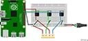
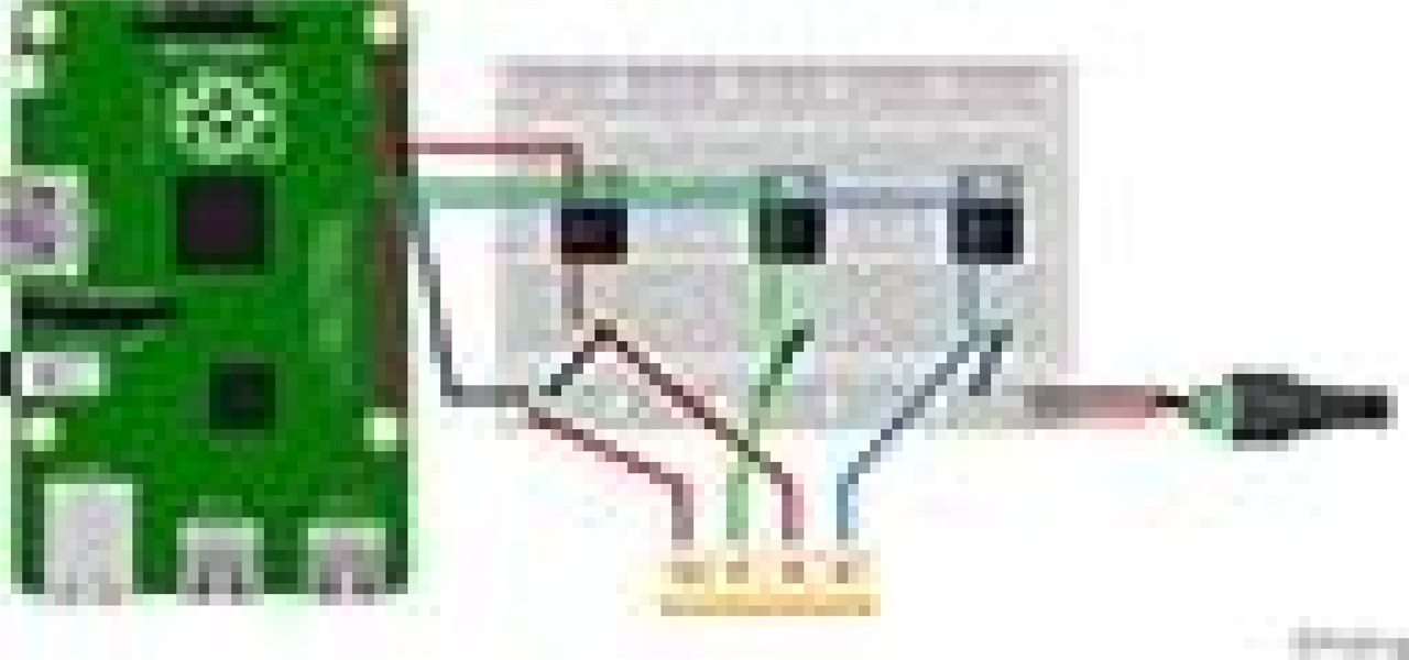
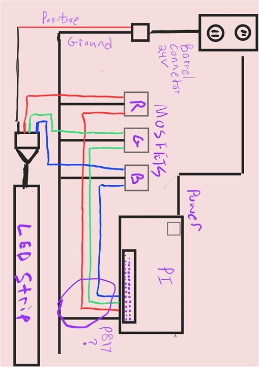
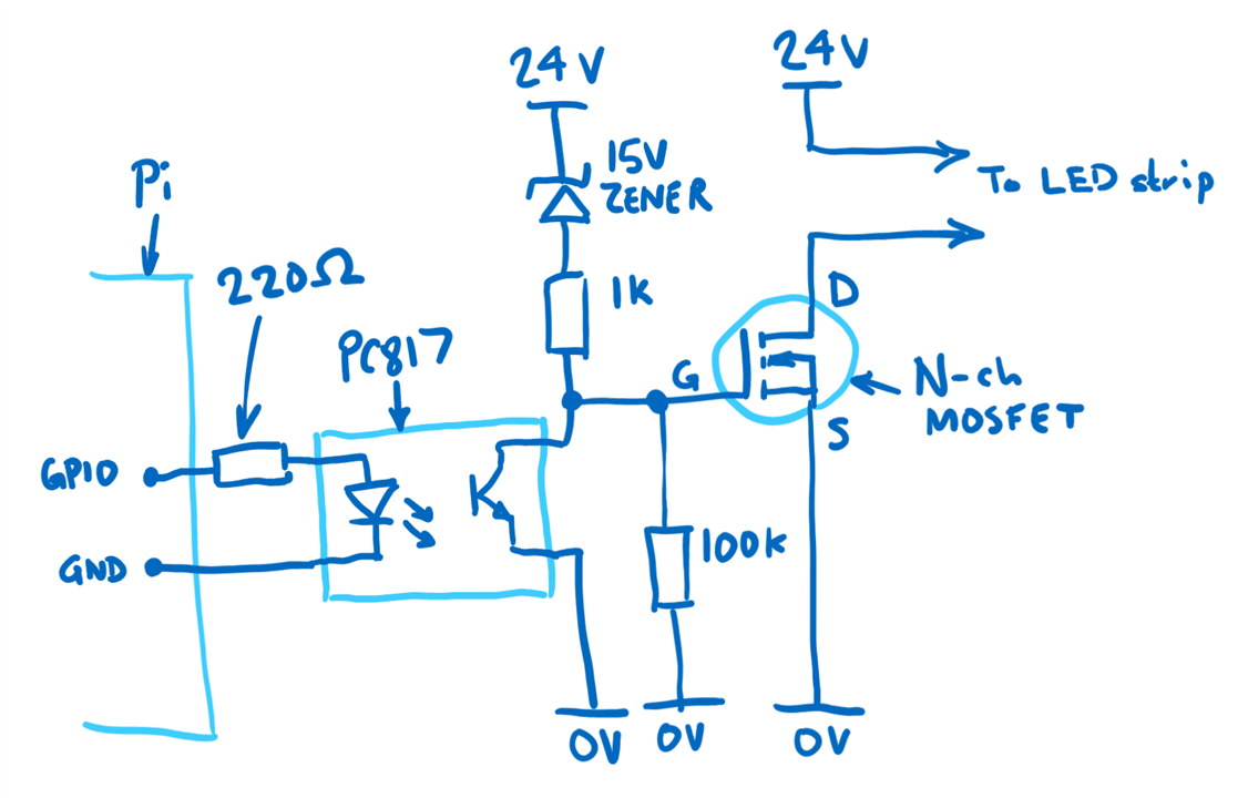
I am having a hard time figuring out the solution to controlling my 24v strip with my Pi 4. I have a 4 pin strip with R. B. G. Bk wires.  I think a N-channel MOSFETs transistor will fix the communication issue and allow control of the colors. most Ara fruit software I have seen is for addressable Leds with only 3 leads. R. Bk. and Green.  Am I on the right track with using the transistors. If so Why? is there an easier way? I am making a bay blade stadium for my son and want to incorporate buttons with lights and sound.. 

  • Sign in to reply
  • Cancel
Parents
  • colporteur
    colporteur over 2 years ago

    My apologies  fskrzycki for my response on using modules solutions to solve problems consuming your post. That was never my intention. 

    You being a new member, it does provide an example of the potential the E14 Community provides. You will need to develop the ability to keep from getting upset or offended by the things other people say and do. You have to have a thick skin when it comes to criticism. Most responses are OK but with 700K members there may be some responses that reflect a lack of emotional intelligence.

    • Cancel
    • Vote Up +1 Vote Down
    • Sign in to reply
    • Cancel
  • javagoza
    javagoza over 2 years ago in reply to colporteur

    I remember one of my early forum adventures when I tried to help out a fellow member with my limited knowledge. I suggested a simple solution, and then this person got all fired up and replied, "Some of us solder components!" Joy My kids still crack up about that post. 

    • Cancel
    • Vote Up +2 Vote Down
    • Sign in to reply
    • Cancel
  • colporteur
    colporteur over 2 years ago in reply to javagoza

    I look on in envy at some of the more advanced techniques members have talked about on the site. I'm happy to have moved from hand drawn PCB's etched in chemicals to KiCAD documents used to manufacture quality PCB's. The tax and duty kills me!

    I think about doing SMD but for the small projects I attempt through-hole works. Call me old school, that is OK.

    Many of careers involved defining requirements. It helps separate the I want from the I needs. Sometimes what you are required to do is not what you want to do. I do value the E14 Community as a knowledge resource. I get some confidence from tapping into others experience instead of going it alone.

    • Cancel
    • Vote Up +1 Vote Down
    • Sign in to reply
    • Cancel
  • fskrzycki
    fskrzycki over 2 years ago in reply to colporteur

    i planned on making a custom PCB. Im i misunderstanding The GPIO layout on my Raspi 4b. i see pin 2&4 are 5v?

    • Cancel
    • Vote Up 0 Vote Down
    • Sign in to reply
    • Cancel
  • colporteur
    colporteur over 2 years ago in reply to fskrzycki

    There is a link for that.

     Raspberry Pi 4 Model B Default GPIO Pinout with PoE Header 

    • Cancel
    • Vote Up 0 Vote Down
    • Sign in to reply
    • Cancel
  • fskrzycki
    fskrzycki over 2 years ago in reply to colporteur

    Questions:  In my current config. I would put the 817 between the Pi and source of my MOSFETS. I think I need to use 3 lines of the optocoupler. 

    Could i connect 3 ground wires to the same Raspberry GPIO pin? 

    Where would you put 817 in this circuit?

    CIRCUIT config.  

    LEDs are controled by a common ground and Three separate Data lines. Strip has a 4 pin connector. Power pin is black(24v) + 3 Data GPIO pins RGB. (3.3v)

    1: power supply positive straight to strip 

    2: RGB MOSFET 1,2,3, drains connected to power supply negative.

    3: Pi Data (pins) RGB MOSFET 1,2,3, source 

    4: RGB MOSFET 1,2,3, Gate connected to LED Strip

    I am using 1 ground pin from the Pi  connected straight to the breadboard power supply ground

    • Cancel
    • Vote Up +1 Vote Down
    • Sign in to reply
    • Cancel
Reply
  • fskrzycki
    fskrzycki over 2 years ago in reply to colporteur

    Questions:  In my current config. I would put the 817 between the Pi and source of my MOSFETS. I think I need to use 3 lines of the optocoupler. 

    Could i connect 3 ground wires to the same Raspberry GPIO pin? 

    Where would you put 817 in this circuit?

    CIRCUIT config.  

    LEDs are controled by a common ground and Three separate Data lines. Strip has a 4 pin connector. Power pin is black(24v) + 3 Data GPIO pins RGB. (3.3v)

    1: power supply positive straight to strip 

    2: RGB MOSFET 1,2,3, drains connected to power supply negative.

    3: Pi Data (pins) RGB MOSFET 1,2,3, source 

    4: RGB MOSFET 1,2,3, Gate connected to LED Strip

    I am using 1 ground pin from the Pi  connected straight to the breadboard power supply ground

    • Cancel
    • Vote Up +1 Vote Down
    • Sign in to reply
    • Cancel
Children
  • shabaz
    shabaz over 2 years ago in reply to fskrzycki

    Hi,

    This needs a diagram. There are inconsistencies, and I cannot tell if they are typos or not. For instance, this part:

    "LEDs are controlled by a common ground" doesn't sit with "Power pin is black(24v)". Can you sketch a quick diagram showing what you mean? In other words, a circuit diagram showing all of the current config, and the MOSFET part code (or web link) so it's all clear what you've got.

    • Cancel
    • Vote Up +1 Vote Down
    • Sign in to reply
    • Cancel
  • colporteur
    colporteur over 2 years ago in reply to fskrzycki

    I have to agree with  shabaz this project needs a schematic.

    You can hand bomb a drawing like the example provided or use a program like KiCAD or Frtizing.  

    • Cancel
    • Vote Up +1 Vote Down
    • Sign in to reply
    • Cancel
  • phoenixcomm
    phoenixcomm over 2 years ago in reply to fskrzycki

     fskrzycki  Nope! you will lose your galvanic isolation between the Pi and the 817  The Pi ground only goes to the 817 input grounds. The Output grounds and the MOSFET grounds must be ISOLATED FROM THE PI. I am making an assumption that you have two (2) power supplies. DO NOT TIE THE GROUNDS TOGETHER. you could end up with a very bad day! like losing your Pi. ~~ Cris H. 

    • Cancel
    • Vote Up 0 Vote Down
    • Sign in to reply
    • Cancel
  • fskrzycki
    fskrzycki over 2 years ago in reply to phoenixcomm

    i am little confused because the 817 needs Two inputs, 1 Ground & 1 Data. with this set up, the voltage spikes are leaking through the MOSFETs

    image

    • Cancel
    • Vote Up 0 Vote Down
    • Sign in to reply
    • Cancel
  • shabaz
    shabaz over 2 years ago in reply to fskrzycki

    There's no detail in the diagram, somehow it has been inserted as a tiny image.

    Could you upload the diagram using the Insert menu item, then select "Image/video/file", and then you'll be able to choose the image file.

    Currently, the image looks like this zoomed in:

    image

    Also, what is the part code (or web link) of the MOSFETs? A photo of the setup will help too.

    • Cancel
    • Vote Up +1 Vote Down
    • Sign in to reply
    • Cancel
  • fskrzycki
    fskrzycki over 2 years ago in reply to shabaz
    • image
    • Cancel
    • Vote Up 0 Vote Down
    • Sign in to reply
    • Cancel
  • fskrzycki
    fskrzycki over 2 years ago in reply to fskrzycki

    • Cancel
    • Vote Up 0 Vote Down
    • Sign in to reply
    • Cancel
  • shabaz
    shabaz over 2 years ago in reply to fskrzycki

    That helps a lot. Based on that, if the circuit so far is successfully operational, then the LED strip is known as common anode (not common ground), which helps understand the circuit.

    The circuit below shows how to insert the PC817. Notice that the Pi's GND is completely isolated from the 0V connection which will be connected to your LED strip's power supply brick.

    With the PC817, the output will be inverted, i.e. you'll have to set the GPIO high to turn off the LED and vice-versa. There's no clean way around that, without changing the design, or inserting more parts (refer to the earlier diagrams to see how that is done). Rather than that, it should be a trivial change to edit the Python code to invert the logic.

    Every component in the diagram below is essential. If you're using a PC817 module (as opposed to just the PC817 component) then, as discussed earlier, the module has some issues. You'd need to remove the LEDs on the PC817 board, and you'd need to replace the 1k resistor on the board with 220 ohms as shown in the sketch here. It would be easier to just buy the PC817 component and not the module, but modifying the module as mentioned would fix it.

    image

    • Cancel
    • Vote Up +1 Vote Down
    • Sign in to reply
    • Cancel
  • fskrzycki
    fskrzycki over 2 years ago in reply to shabaz

    i understand. Just to be clear the circuit above is for one color only.. if I go with using the 817 component, can I use the same gpio ground pin for each color? 

    • Cancel
    • Vote Up 0 Vote Down
    • Sign in to reply
    • Cancel
  • fskrzycki
    fskrzycki over 2 years ago in reply to fskrzycki

    Can the overvoltage protection be the same component in the example above? I think you have the Gate/Source/Drain on the MOSFET mislabeled. can you double check 

    • Cancel
    • Vote Up 0 Vote Down
    • Sign in to reply
    • Cancel
element14 Community

element14 is the first online community specifically for engineers. Connect with your peers and get expert answers to your questions.

  • Members
  • Learn
  • Technologies
  • Challenges & Projects
  • Products
  • Store
  • About Us
  • Feedback & Support
  • FAQs
  • Terms of Use
  • Privacy Policy
  • Legal and Copyright Notices
  • Sitemap
  • Cookies

An Avnet Company © 2025 Premier Farnell Limited. All Rights Reserved.

Premier Farnell Ltd, registered in England and Wales (no 00876412), registered office: Farnell House, Forge Lane, Leeds LS12 2NE.

ICP 备案号 10220084.

Follow element14

  • X
  • Facebook
  • linkedin
  • YouTube