


Introduction
I recently had a need to wind a thousand turns of wire or so on a bobbin, but I might have needed to repeat it a few times each time the coil design needed tweaking. I needed a coil winder! This project might also be useful for DIY'ing electric guitar pickups, or the information in the blog may be handy if you wish to use vacuum-fluorescent displays (VFD) or stepper motors in projects.

There are coil winding machines on ebay, but most of them look pretty primitive. I decided it was worth spending a weekend trying to come up with a suitable method. This blog post describes the protoyping work, which does function, but is fragile with wires everywhere. The next step, in part 2, will be written when the PCB design is complete and a lot more rock-solid construction is achieved.
There’s a 2-minute video demo here (YouTube link):
Some Possible Approaches
Many of the simpler coil winders are manual, with a mechanical counter for the number of turns. I decided to use a motor. One approach is to try to use an electric drill for this purpose, but the wire was going to be very delicate, and might have snapped.
I briefly tried a normal brushed DC motor, using a magnet for the rotational feedback. This works fine in theory, but it needs a good mechanical design to hold the magnet in alignment. Some brushed DC motors do not have the spindle on both ends, which makes the magnet attachment for precision measurements slightly more difficult. The motor plus magnetic sensor approach had the theoretical advantage of having very low parts cost. Nevertheless, I gave up on this approach due to the mechanical problems; I’d rather be solving more electronic or software problems!
I used a compromise method; a stepper motor! This has the advantage that closed-loop turns feedback isn’t essential, if the number of times the motor coils are energised are counted!
A significant disadvantage is cost, but a major advantage is simplicity in mechanical construction. Besides, cost matters less when a project is a one-off, and not intended for sales!
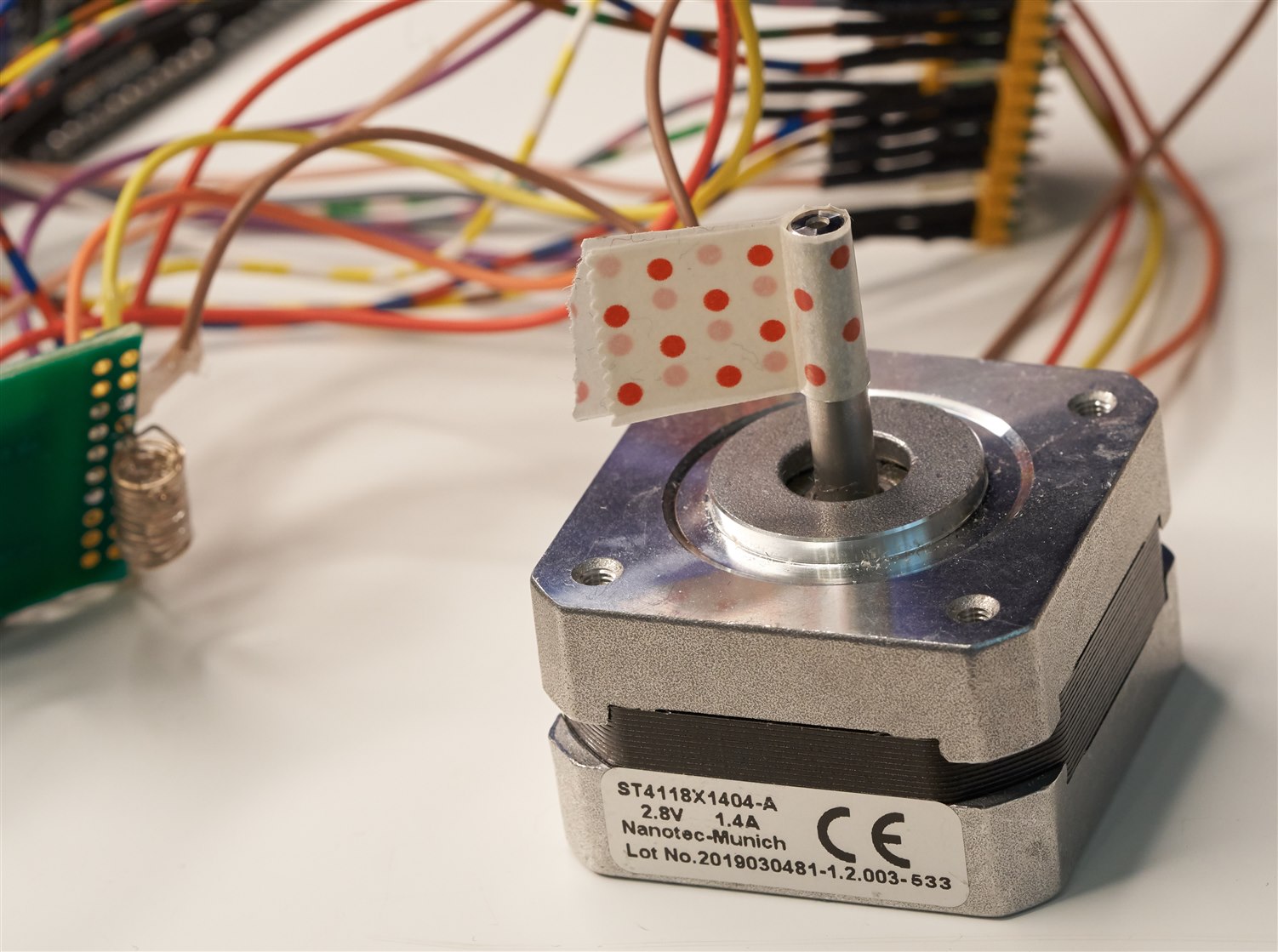
To maintain accuracy, I simply scaled the project to use a large stepper motor ; it is less likely to slip if there is lots of torque.
Stepper Motor Control with L6219 Driver IC
There are plenty of nice stepper motor modules available pre-built. I didn’t have any of these handy, but I did have a box of old semiconductors, and it contained a bunch of L6219 parts! These are about as classic as they get; the ST L6219 is an ancient design, at least three decades old. It has inefficiency, and probably less protection than modern stepper motor driver ICs. However on the plus side, it is cheap, and actually performs reasonably well (it can control the motors in a ‘half step’ mode for smoother movement, and the L6219 will also control the level of current through the windings to try to make the travel reasonably smooth, considering that it’s a very old design.
Surprisingly there’s not a lot of examples of this chip being used. The PDF datasheet showed that it is not very difficult, it just requires slightly more microcontroller signals compared to newer chips. Six digital signals are used, plus a fixed voltage level to the chip's Vref pins, that determines the maximum current output before protection kicks in.
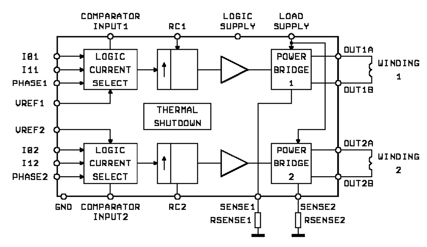 Image source: st.com
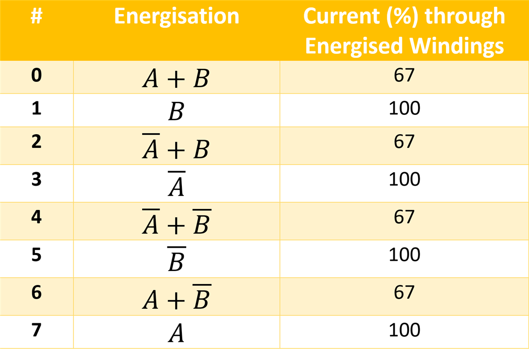
To implement half-step operation, one has to implement that in the microcontroller. The two windings of the stepper motor are energised either in the forward or reverse direction, at either full current or at two-thirds current. The table below shows how the windings are energised, under control of the microcontroller.
The L6219 can offer up to 750 mA of continuous current. The stepper motor that I used is capable of handling higher current, from a more powerful motor driver. However, for the kinds of could I will be winding, I don’t think I will need any extra power, it already seems reasonably powerful. I might re-think that later.
When using the L6219 chip, the maximum current is set using a sense resistor, plus a voltage level applied to a Vref pin. The current is Vref/(10*Rsense), so if Vref is 3.3V, and Rsense is 0.5 ohm, then the maximum current will be 0.66A.
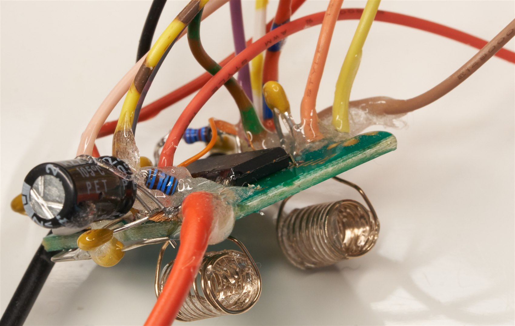
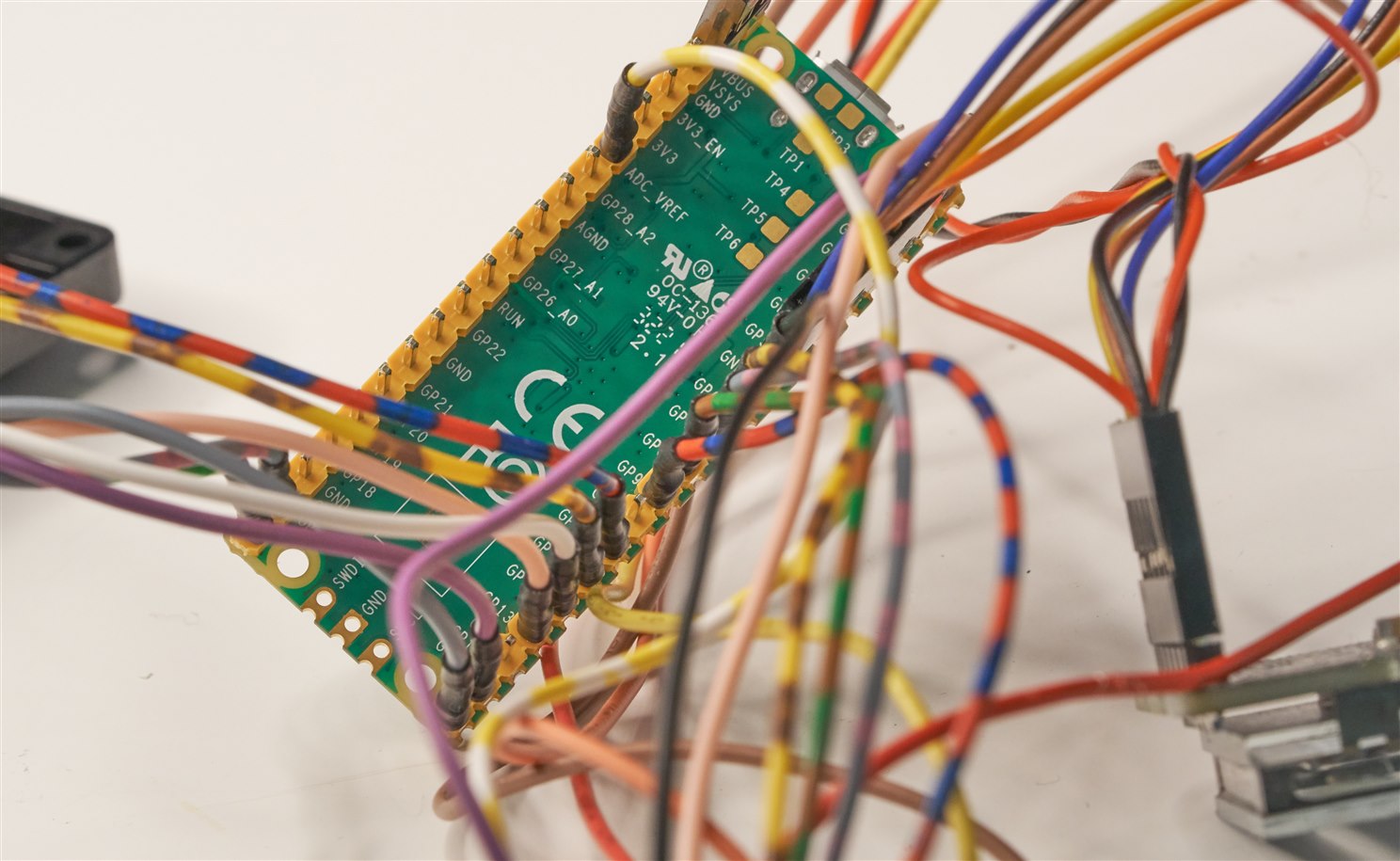
Construction isn’t great; it was rapidly prototyped. As soon as it was working, I secured the wires with glue so that hopefully it mostly survives until a circuit board can be made!

Display
This was an easy choice. A Vacuum Fluorescent Display (VFD )would look very neat. The VFD attaches directly to the Pico’s GPIO pins, and is powered from 5V. For more information, see Using a Vacuum Fluorescent Display (VFD) with a Microcontroller
Keypad
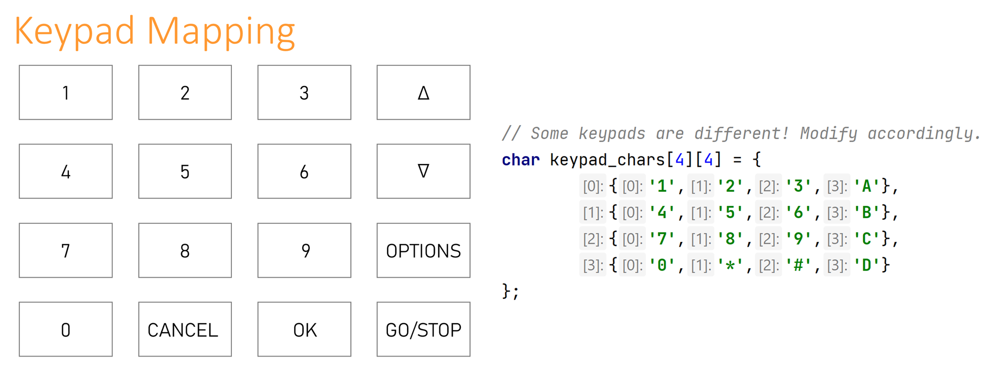
I used a random keypad that I had. It is a standard 4x4 matrix design, so for anyone who wishes to replicate the project can use any 4x4 matrix keypad. It is easily reconfigurable in the code; see the diagram below.
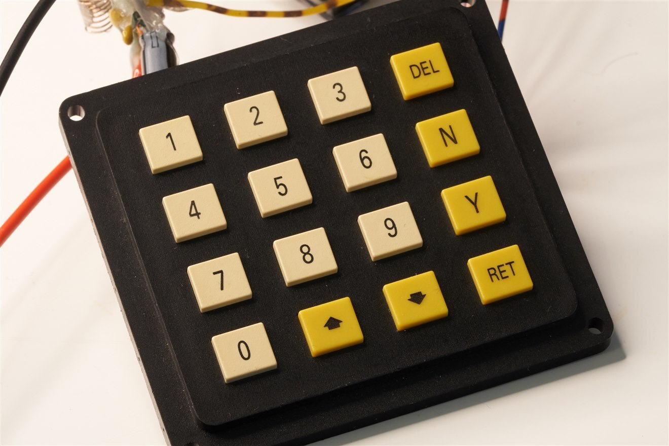
Each button is referred to in the code by a single character. So, for instance, the CANCEL button is the character ‘*’. If you desired for the CANCEL button to be (say) at the bottom-right corner of the keypad, then the array would be modified to swap the ‘*’ with ‘D’ perhaps.
Power Supply
A 24V supply can be used, however it functions with a 12V supply too. Anything 12-24V should be fine. A small 5V DC-DC switching converter module is used. For QAQa|the Pico’s supply, I used the simplest way of feeding power to it, using a Schottky diode.
Circuit Diagram
The Pi Pico interfaces just fine with all the other bits and pieces. There's not a lot to the circuit:

Operating the User Interface
This is easier to describe with the diagram below. The way I figured I’d design it, was to ordinarily assume that any value entered is the number of desired rotations. So, typing 100 followed by OK would set the desired turns. That’s the Normal mode, and can be used any time, regardless if the motor is rotating or not. The motor speed can be modified at any time using the up/down buttons.
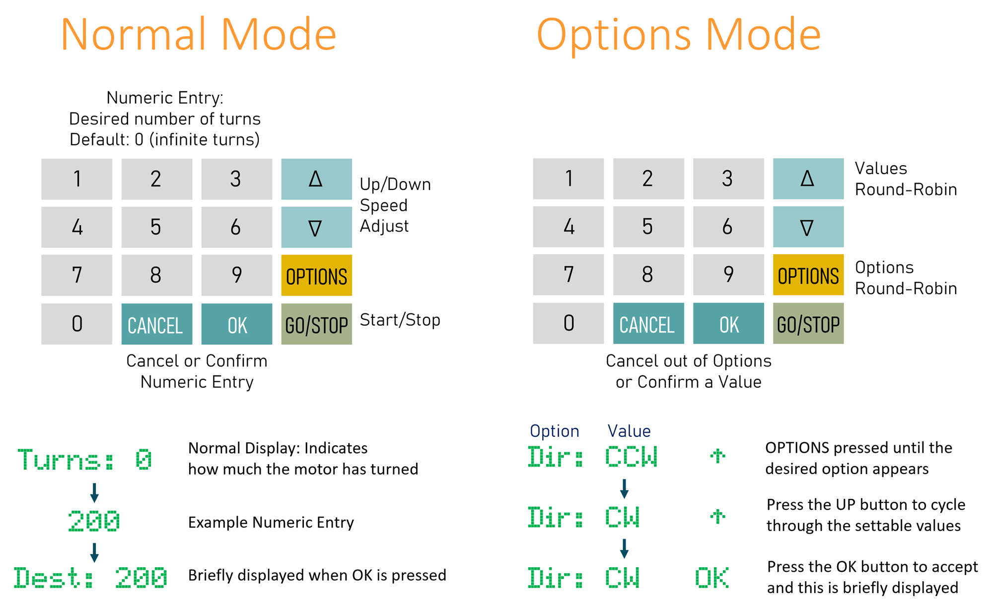
To change a setting, or for lesser-used features, there is an options mode. It currently only has two options; direction, and zeroize. The zeroize merely sets the turns counter to zero (or you could just power-cycle the unit). Technically the options can be modified while the motor is spinning too, but it’s probably not recommended to switch the direction while it is spinning at speed! I’ll maybe lock out that in a later code release (the code is extremely prototype-level currently).
I think it’s fairly straightforward to use, but for sure it’s not very feature-rich. I think I will add an options mode to allow manual operation (i.e. only spin the motor while a button is held down). Also, it would be nice to properly handle fractional turns, which I’ve had in the back of my mind but not coded yet.
Software
Everything is controlled by the Pi Pico, and coded in C/C++. The code isn’t pretty, it was written within a day. It is available on GitHub.
Mechanical Thoughts
The motor spindle is of a good length, so I think it will be easy to create attachments to bobbins and so on. There could be a need for support on the other side of the bobbin, like a lathe’s tailstock. There is also an argument for being able to control a second motor, to guide the windings. The motor driver code will support an additional motor if that is needed, but for now I will just manually guide the wire - but I'll lay out the printed circuit board with space for the second driver. With a more automated system, a wire guide and tensioner will be needed, a bit like a sewing machine probably. I don’t intend to do that for a first attempt. This isn’t intended to be a production-grade coil winder!
Next Steps
The circuit and code seem to function OK enough, but the prototyping is quite ropey, it needs a circuit board. Once I have a better assembly, I can focus on the coding a bit more, to add additional features, and to try it out on some coils I need to wind!
Thanks for reading.
Top Comments