


Introduction
Working on a recent Pi project, I needed to use some servo's. This blog post discusses a servo controller project that can be used for toy and model cars, planes, model robots and so on. There are existing controllers out there, but I didn’t have one, and besides some of them seemed expensive – I didn’t want to spend $15+ on something I could make for $2. Also this was an opportunity to try to design something hopefully better (in some ways) than existing off-the-shelf controllers, and also explore how to create a custom hardware peripheral for attaching to the Pi. It isn't hard, anyone can do it : )
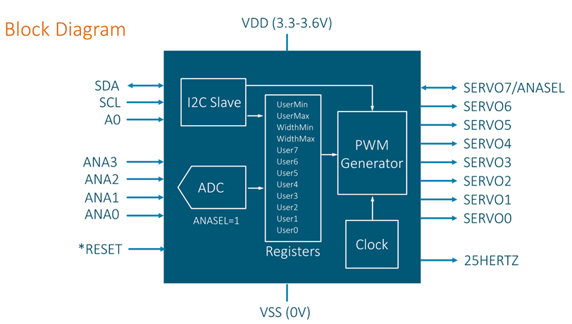
The aim was to build something that could connect between the Pi (or any other single board computer or micro-controller, such as the Beaglebone, Arduino, and so on), and the servos, as shown in red here. It is explained in more detail below, but in brief, it would allow the Pi, or any micro-controller of choice to communicate using a standard I2C interface, and the servo controller would generate the correct pulse width modulation (PWM) signals to control multiple servos, which would create the motion for the desired task.

But first, it is good to understand the Servo, to know how to use it and its strengths and weaknesses.
What are Servos'?
When motors are running, it is hard to know how much they have turned, and when to shut off a motor precisely, to do accurate things like robotics. It would also be nice to adjust the voltage so that the motor can accelerate and get stuff done, but slow down as the robot approaches a human! Servo systems are different from standalone AC or DC motors in that they have feedback. The feedback can be used to precisely control the motion (position and speed). In industrial scenarios, servo motors are composed of an AC or DC motor (specially built to have very smooth rotation) and a rotary encoder (a device that generates pulses on a wire as a shaft is turned), and circuitry known as a servo amplifier (an amplifier just generates a voltage based on an input signal). This is connected up to the industrial machine controller or robot brains (using a digital interface) and position and speed commands are sent digitally to the servo amplifier. Much like any amplifier, it will generate a voltage, which drives the motor in either direction depending on the polarity of the voltage. The feedback from the encoder is used as an ‘error signal’; as it approaches the desired settings, then the servo amplifier output voltage is reduced, therefore allowing the motor to slow down and stop as it approaches the correct position. The machine cannot be knocked out of position, because the encoder will generate pulses that produce an error signal into the servo amplifier, which will generate a correction voltage to bring the machine back to where it was specified to be according to the original message sent from the machine controller.

In hobby territory, a similar system is used but compacted into the space of a few cubic centimetres. Instead of a high-performance motor, often just a brushed DC motor is used, although higher-end hobby servos will have brushless motors. The rotary encoder is expensive so it is swapped out with a cheaper (and lower-performance) alternative: a variable resistance, known as a potentiometer. The servo amplifier is composed of an analog to digital converter (to read the potentiometer resistance) and the amplification occurs using digital pulses and a H-bridge. Instead of a fancy isolated digital interface, the hobby servo uses a PWM input signal where the pulse width determines the position that the motor should move to. Instead of multiple rotations that may be needed to move industrial machines into position, the hobby servo often just rotates through a smaller rotational distance – maybe only 180 degrees for example – to suit hobby requirements such as controlling toy wheel steering or model aeroplane surfaces. Instead of a direct connection from the motor shaft to the industrial machine for the best precision, the hobby servo has to make do with limited power and will have gearing on the output shaft; this will introduce some slack, also known as ‘backlash’, which can reduce accuracy further.
If you break open a hobby servo, you'll see all these components. The PCB will contain the circuit that takes the desired motion signal (the PWM input), and the H-bridge circuit which is switched on and off rapidly to generate an average voltage to drive the motor. Instead of the rotary encoder attached to the back of the motor, there will be a potentiometer near the motor, attached via a gear. There will be three wires egressing from the servo; two of them are for the power source, and one of them is for the input PWM signal referenced to the ground wire.
How are Hobby Servo Motors Controlled?
Hobby servos come with a three wire connection; the power connections (around +4.8 to 6V DC and 0V connection) and a PWM input connection which can be driven by a 5V logic level signal, but 3.3V seems to work too usually.
The PWM rate is about 50Hz, although it is non-critical. The high pulse width is what controls the position of the servo. The actual values vary wildly from one hobby servo type to another. Sometimes a value of between 1000usec to 2000usec (1 to 2msec) is stated to move the servo shaft from its extreme clockwise position to its extreme anti-clockwise position (looking at the servo shaft end-on). A value outside of the range will not cause any additional motion. Other hobby servos may use a different pulse range, such as between 600usec and 2400usec. In most cases the centre position can be assumed to be achieved at about 1500usec pulse width.
The PWM pulses (at that 50Hz rate mentioned above) need to produced with little jitter in the pulse width, otherwise the servo will make a chattering noise as the servo amplifier keeps generating a voltage to adjust the motor on every slight change in the generated pulse width. Although PWM pulses can be produced with just timer circuitry (such as with 555 timer chips), a more popular way is to use digital circuits or computers/microcontrollers.
Trying to generate PWM pulses in software is not easy, because most computers are not designed for such tasks. They will produce slightly varying pulse widths with lots of jitter! Single board computers such as the Raspberry Pi or BeagleBone Black often have dedicated circuitry inside that can generate pulse trains with accuracy. But often SBCs are not designed to control many servos simultaneously. Furthermore, their dedicated circuitry is for general pulse trains, and so some coding is needed to make it suitable for use with the pulse width sizes required for operation with hobby servos, which is fine, but for quick projects sometimes it is easier to offload the PWM generation to an external chip, and just send instructions from time to time (using a serial interface such as I2C or UART) whenever the position of the servo shaft needs changing. I2C and UART capabilities are present on nearly all SBCs and microcontrollers, so these are handy interfaces to use.
What else is out there?
A google search revealed that one way to control it is to use a PCA9865 chip. This generates sixteen PWM outputs for general purposes (primarily to control LED brightness), under I2C control. It isn’t dedicated for servo use, so the developer still needs to do a lot of coding to make it achieve the desired effect. Adafruit has some library code for it.
The PCA9685 has only 12-bit resolution, and this means that the granularity of a servo is not being used to its full potential. As an example; my cheap SG-5010 servo (which rotates across its full range with a pulse width between 400 and 2350usec) has at least 500 visibly discernible steps (about 0.35 degrees per step) from its most anti-clockwise to its most clockwise position (to find this out, I varied the pulse width gradually, and counted how many discrete movements I could see).
A PCA9685 servo controller set to output pulses every 50Hz, can only resolve 390 steps due to its 12-bit resolution. To improve this, the pulse rate could be increased, but even at 60Hz, the PCA9685 can only resolve 475 steps. A better quality servo than my SG-5010 may well have a resolution in excess of 500 steps. Hobby servos are not accurate devices and so each step will not be identical. Also there be backlash in the end mechanism that the servo is connected to. Nevertheless there could be a requirement to finely trim the servo position as closely as possible, and that is harder to do with just 475 steps available.
One other thing that bothered me, was that if I was to use a PCA9685, I’d have to do a lot of calculations in the controlling software. The PCA9685 as a generic PWM device does not understand degrees of rotation, or lengths, or percentages of full travel. These have to be done by the user, or in the library code, to translate into a number that the PCA9685 understands.
There are also dedicated, fully built modules but at prices that make no sense (to me anyway).
This project was an opportunity to try to address all these problems (and hopefully not introduce too many new ones!).
The Design
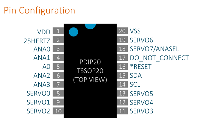
To make this project nice and easy, I used a 20-pin DIP chip – a Texas Instruments MSP430 microcontroller. It is very low cost, easy to hand-solder, the programmer is cheap at $10 and it doesn’t need a lot of software installed on the PC. The steps to program the chip are described in this other project Cyclops-1000: An Electronic Eye for Rotational Speed Measurement (see the section Working with the Microcontroller).
In contrast the PCA9685 supports up to 16 servos, but for my project I was going to aim for just 8. I figured 8 servos is a good quantity to start with, and if the user wishes to add more, then the I2C bus supports adding more ICs. I’d rather control 8 servos more accurately and with more features, than have a board with 16 servos controlled with less accuracy and less features.
The MSP430 will be coded up to implement the design shown in the block diagram below. It was fun to plan how it should work; that's the benefit of using a microcontroller instead of someone else's servo controller! The microcontroller datasheet was used to check that each pin could do what was desired.
For future flexibility, some pins were allocated to be usable for analog inputs too, since the microcontroller datasheet shows that those pins support that capability.
An address pin (A0) was created in the design to allow two of these devices to be connected to the I2C bus.
Since there are only 20 pins available with this microcontroller, I reused one of the servo pins to also work as a mode switch. This is a typical trick where the pin can be programmed as an input at power-up, and if it detects a certain voltage level then the code internally switches modes of operation.
| Pins | Description |
|---|---|
| SERVO0-SERVO7 | Wire up the servos here |
| SDA,SCL | I2C interface to the Pi, Arduino, etc. The Arduino will require pull-up resistors to 3.3V. The Pi already has these. |
| A0 | Leave disconnected to use I2C address 0x31. Short to ground to use I2C address 0x30. |
| VDD | Connect to 3.3V, and have a capacitor (100nF) to ground |
| VSS | Ground connection |
| *RESET | Connect a resistor (47k) and capacitor (1nF) here, to generate a reset pulse when the power is applied. |
| ANA0-ANA3 | Optional analog mode. Connect potentiometers here for driving SERVO0-SERVO3 |
| SERVO7/ANASEL | Connect to +3.3V via a 1k resistor, to have the analog mode enabled. It is not possible to use all 8 servos in analog mode |
| 25HERTZ | Connect a resistor and LED here to have a flashing indicator |
I2C Commands
The block diagram above shows that there are about 12 different parameters (registers) that can be sent to the controller from the Pi/Arduino. This is just an initial design to get things progressing, and more capabilities could be added later.
I2C commands will be used to set the position of each servo, but there are also commands to set the min/max width of the pulses that the servo expects, and also the user-friendly number range that is desired. So, if I had a 180 degree servo where the datasheet specified that it needed pulses between 800 and 2200usec, and for my application I wanted to specify the motion as a percentage between 0 and 100 (100 representing 180 degrees) then I’d want to configure the controller with these parameter values using I2C:
WidthMin = 800
WidthMax = 2200
UserMin = 0
UserMax = 100
Then, to move the fourth servo (SERVO3, since the numbering starts from zero) to its halfway or centred position, I’d want to set this parameter value:
SERVO3 = 50
I needed to construct some system for sending these parameters over I2C. I settled on this:
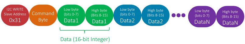
The first byte will always be the slave address (0x31, or 0x30 if the A0 pin is connected to ground). The second byte will be the desired command. A command of 0x00 will mean SERVO0. 0x01 will mean SERVO1 and so on. There will also be commands to set the width and user min/max values.
The actual settings will be 16-bit integers, which means that two bytes are needed to send them. The ordering is least-significant-byte first. Here are the I2C values to set the fourth servo (SERVO3) to the decimal value 50 (which is 0x0032 in hexadecimal):

In Python on the Raspberry Pi this is easy, it takes just three lines:
from I2C import I2C
servo=I2C(0x31)
servo.write_subaddr_int(3, 50)
Line 2 shows the I2C interface being set up to communicate to the 0x31 slave address, and line 3 shows that servo 3 (fourth servo) is being set to the value 50. That write_subaddr_int function will automatically convert the number 50 into a two byte integer and send all the bytes in the correct order.
Wiring It Up
The top view pin configuration that was chosen is shown here:
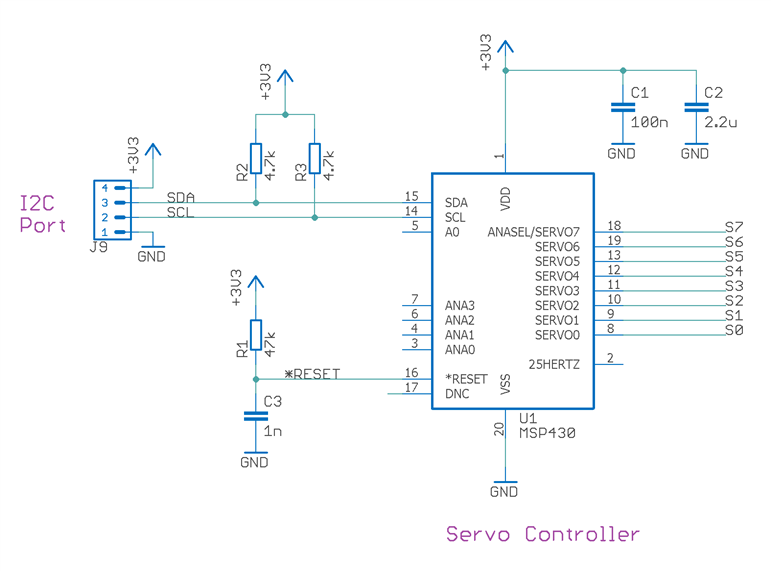
Here is how it would be connected up to a servo (more servos can be added of course):

The schematic is shown below. The resistors R2 and R3 are pull-up resistors for the I2C bus. The Pi already has them so R2 and R3 are not needed for it, but the Arduino would require them. Note that the simpler Arduino boards (like Arduino Uno) use a 5V supply, but this servo controller uses 3.3-3.6V, so the SDA and SCL pull-up resistors must go to the 3.3V pin on such Arduino’s, and not to the 5V pin.
Resistor R1 and C3 form the reset circuit. Capacitors C1 and C2 provide supply decoupling to the microcontroller. Capacitor C4 provides supply decoupling for all the attached servos.
Summary
This first part of this mini-project investigated the motivation to create a $2 servo controller that could in theory perform better and have more features that existing off-the-shelf options. The operation of servos was described, and how the design could look internally with an I2C instruction decoder and PWM generator. A format/scheme for sending commands was also created, and the wiring diagram to see how it could be used. As next steps, a PCB will be created, and some coding will be done!
Top Comments