


Table of Contents
Introduction
This blog post discusses how to control multi-colored lighting using a Pi Pico. This project could be assembled together in a matter of hours, because it uses very few parts.
If you visit the CPC website, you’ll see a load of low-cost DMX controlled multi-colored lighting, such as spots, light bars, and even moving lights on motorized gimbals, and so on; all these are great for parties!

The lighting is usually powered from the mains of course, but the control interface is exposed/misused on a three-pin circular connector called XLR and multiple lights can be chained for operation from a single controller.

Electrically, the communication uses a protocol called RS-485 which uses three wires, called A, B and GND. Sometimes A and B are labelled Data+ and Data-, or Non-Inv and Inv, respectively (there's no damage if the A and B wires are accidentally swapped, it just won't work until corrected). The DMX protocol runs on top of that, and usually consists of a sequence of 512 bytes (actually 513 but the first one is unused) of data, and usually sent repeatedly at speed.
The 512 bytes can take values from 0 to 255, and it’s up to the attached lighting which of the 512 bytes in the sequence will be of interest to that attached light. More often than not, that value represents a brightness level. For RGB lighting, three consecutive bytes may be used for the three levels. The user manual for the light will explain the specifics, and it is up to the user to configure their lighting controller accordingly. More complex lighting may use more complex configuration than the simple single- or three-byte explanation outlined here.
For more technical detail about DMX, see the following blog post: (+) DMX Explained; DMX512 and RS-485 Protocol Detail for Lighting Applications - element14 Community
This blog post explains how to use a Pi Pico, or any RP2040 microcontroller board, to build a DMX controller that can be operated from a PC. This is a very quick project, I didn’t spend a lot of time on it, because I don’t have an immediate need for this. The underlying reason for this project was to just test out some custom hardware needed for a non-DMX purpose, but it had the right interface (RS-485) for lighting control too!
Circuit
Just a few wires need to be connected, from a Pi Pico board, to a 3.3V RS-485 transceiver board.
GPIO 0 : UART TXD (output from RP2040), connected to input of RS-485 transceiver
GPIO 1 : UART RXD (input for RP2040), currently unused
GPIO 2 : Driver Enable, connected to both the DE pin and the *RE pin of the RS-485 transceiver
GPIO 12: Connect this to an LED (via a suitable resistor). The LED simply lights up to indicate if the firmware is running, but it may be used for other purposes in the future.
Here's an example RS-485 board that could be used; the key thing is to select a 3.3V version (because that's the logic level voltage that the Pi Pico uses), not 5V!

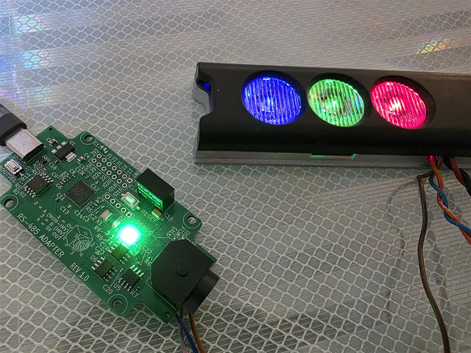
The photo shows my setup, which uses a custom board that contains the RS-485 interface built-in, but you could just use a Pi Pico and a separate RS-485 transceiver board. As an example, the three LEDs on the DMX light shown in the photo, are controlled by DMX channels (bytes) 1, 2 and 3, from the 512 bytes that are repeatedly sent.
Code
I used AI to write the code. I already had simple DMX test code I’d written myself a few years ago, so I gave that to AI to guide it to rewrite with the new features I wanted. The code uses the excellent Pico-DMX library that uses the RP2040 PIO controller (for info on that, see the RP2040 PDF datasheet, PIO chapter).
The RP2040 is a dual-cored microcontroller, and one core is used to repeatedly send out the DMX sequence, and the other core is used for user input.
To build the code, download it from the dmxtester GitHub repository. You’ll need to set up the PC for C/C++ development for the Pi Pico. It’s beyond the scope of this blog post to explain how to do that, because it depends on the operating system, and user preferences, and there are many articles online. Personally, I downloaded the Pico C/C++ SDK and ARM GNU Toolchain, but others may prefer to install the official Raspberry Pi software bundle.
My build procedure is to just type ./build.ps1 from a Windows PowerShell, but if you’re using the Raspberry Pi installed environment, then you may be able to build from within VS Code (I don’t know because I’ve never tried).
Whichever method you use, once the firmware has been built, it can be uploaded to the board using the BOOTSEL button as shown in this video: https://www.youtube.com/watch?v=os4mv_8jWfU
My board happens to have a BOOTSEL and a RESET button, so it was a little easier (no need to start from unplugged USB if you have a reset button to use instead).
Operating the Project
This simple DMX Tester can be used with any serial port console software. Find the port number (such as COM4) that appears in Windows Device Manager, and then open it at 115200 baud using the console software. Hit Enter to see a dmx> prompt.
Typing help displays the following:
dmx> helpCommands: help Show this command list set_chan <channel> <value> Set channel 1..512 to 0..255 get_chan <channel> Read channel 1..512 set_all <value> Set all channels to 0..255 set_rgb <first> <r> <g> <b> Set three consecutive channels blackout Set all channels to zero status Show DMX transmitter statistics
You can see it is mostly self-explanatory to use.
Summary
A low-cost Pi Pico, and an RS-485 board, were together used to control DMX lighting.
The simple DMX Tester project could be extended, for instance, to allow programmatic control, and to store and play back lighting sequences. I'd like to extend it a bit more at some point, when there's time. If you give it a try, it would be great to see photos of the lighting in operation : ) and please share any features you add to the code, to help others too.
Thanks for reading!


