


Table of Contents
Introduction
There are lots of nice character and graphic displays, but sometimes all that’s needed is to be able to show a few digits. Bare non-intelligent 7-segment LED displays can be very useful, but they are awkward to wire into a project quickly. This blog post describes a very simple project, it is nothing more than a breakout board with digit multiplexing.

The main advantage of this project is cheapness : ) A 7-seg display can cost as little as 60p in small quantities in the UK (and probably less if you shop around), and several different manufacturer 7-segment displays will fit the board. The main disadvantage is that you’ll need to dedicate at least 8 GPIO pins to drive it, and obviously the code will need to handle the digit multiplexing.
The board can be broken into the desired number of digits from 1-4, and either a SIL pin header can be used (ideal for breadboard or protoboard wiring) or the thin end can be cut off and a DIL pin header can be used (with ribbon cable for instance). The rendering below shows the pin header mounted on the top side, but it would more likely be fitted on the underside.
Also, the board can directly plug onto the connections on the right side of the Pico-Eurocard, to give it this simple display functionality.

Circuit
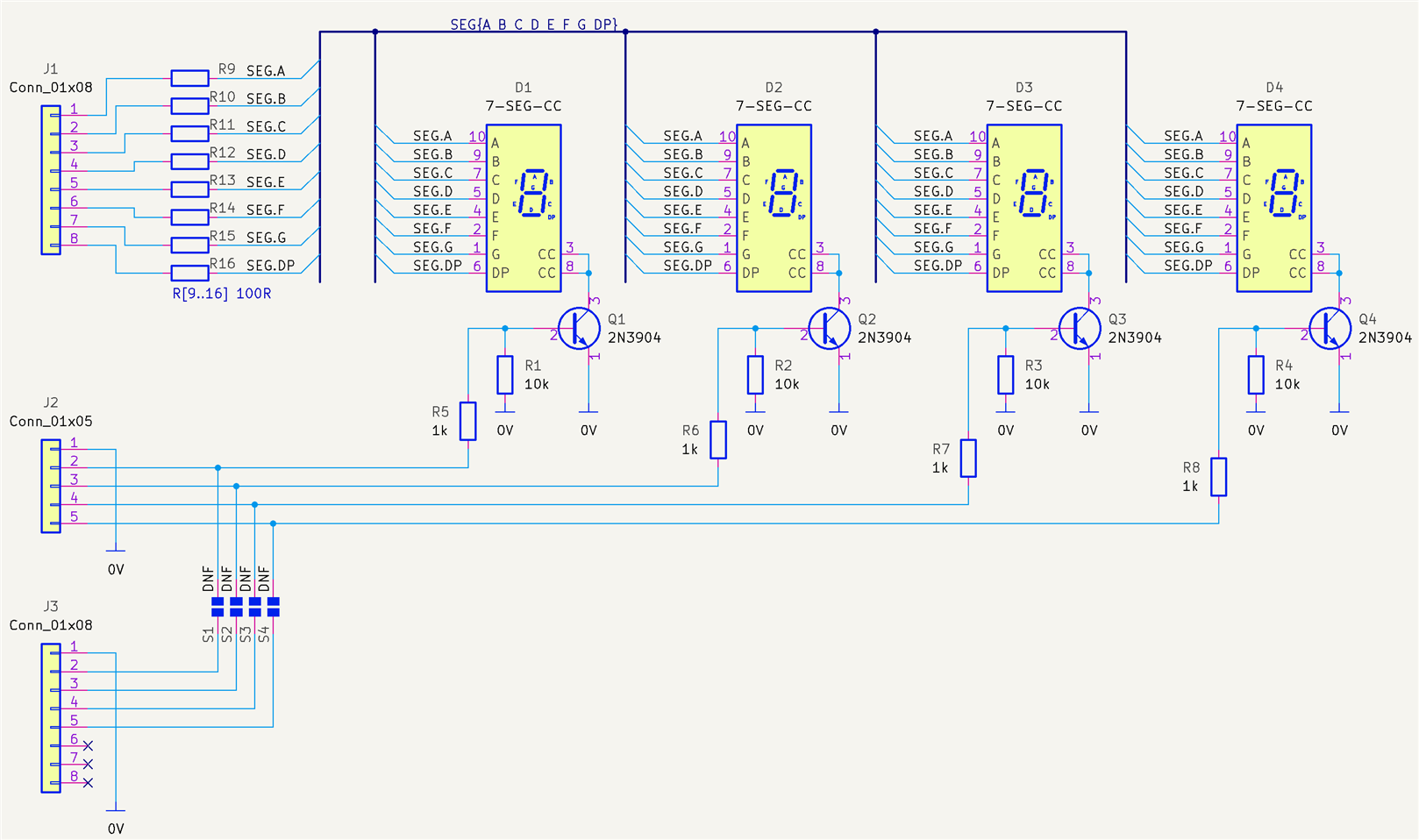
The circuit diagram is shown below. All the 7-segment displays are connected together except for the cathode connections, which are controlled in sequence using the GPIO connections to the transistors. There’s not much else to say here.
Printed Circuit Board
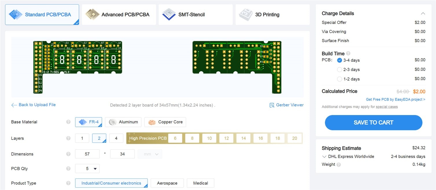
The PCB layout is shown below. It is designed to be easily hand-solderable using large parts. The notches in the sides of the board may be helpful if mounting it inside an enclosure.

The boards can be ordered by uploading the zip file (attached to the blog post below) to any PCB manufacturer; there seems to be no issue regarding the snappable areas of the board, but I have not ordered it yet:
Supported 7-segment displays include:
TDSR-3160
SC39-11EWA
3191AS (AliExpress)
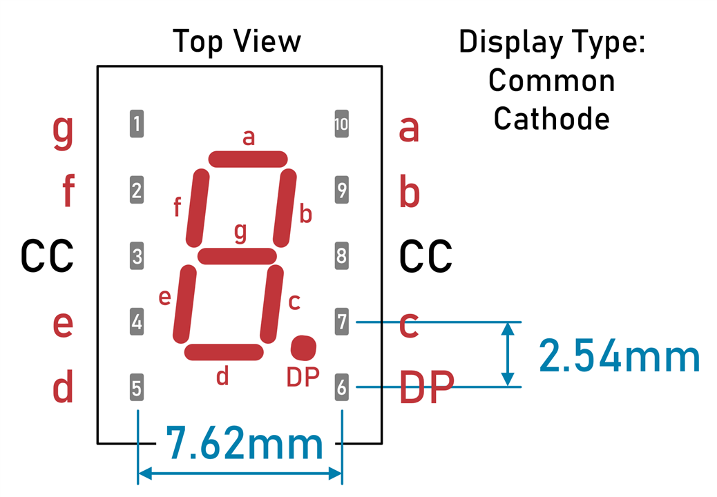
I have only tested TDSR-3160. 7-segment common-cathode displays with the pinout and pin spacings shown in the diagram below will fit. Note that some displays use pins 1 and 6 for the common-cathode connection, so watch out for that, because this board layout uses displays with pins 3 and 8 being the cathode connections:
Prototype
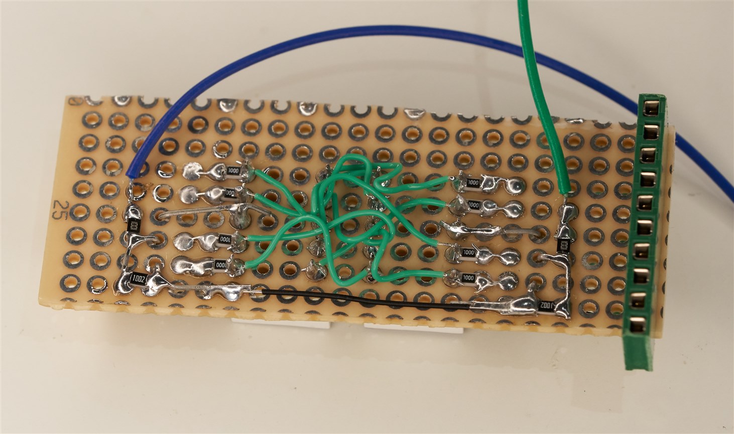
I prototyped a couple of the 7-segment displays onto a piece of perf-board, to try it out.
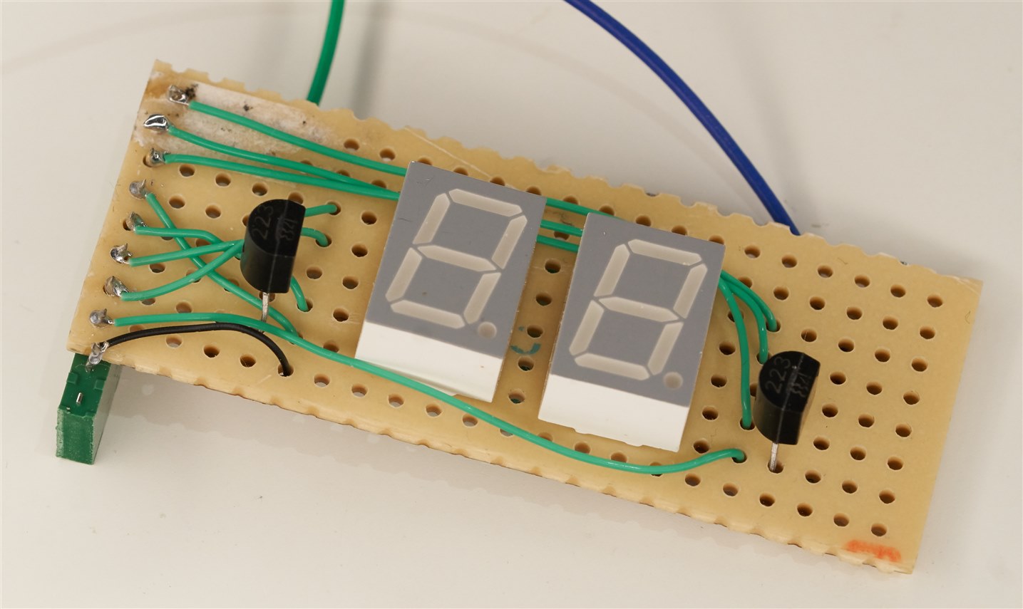
High-efficiency LEDs would be good, which I didn’t have. I used non-high-efficiency 7-segment displays (the ones I used are manufacturer code TDSR-3160), but it was still fine for two digits.
Lots of messy wiring : ) Looking forward to having the PCBs!
Display Filter
Things look a lot better with a filter (this is a ‘neutral’ filter, in particular filter code ‘ND4’):

Driving the Display
In brief, the microcontroller code needs to drive the segments for each digit sequentially, with the cathode drive being switched from digit position to the next, repeatedly.
It could be handled in a loop but that is very tiresome for the rest of the code for the desired end application. A separate display task could be a possible option if there is an OS involved, otherwise a timer could be employed.
The code here shows how the display can be driven with a microcontroller. The example assumes a Pi Pico is being used with the C SDK, using a timer. The code is only for two digits since that’s all I’ve tested, but it would be easy to modify to an arbitrary amount of digits.
/************************************************************************
 * 7seg test
 * main.c
 * rev 1.0 - January 2023 - shabaz
 ************************************************************************/

// ********** header files *****************
#include <stdio.h>
#include "hardware/gpio.h"
#include "pico/stdlib.h"
#include "hardware/pwm.h"


// ***************** defines ***************
// GPIO pins for 7-seg display
#define SEG_A_PIN 8
#define SEG_B_PIN 9
#define SEG_C_PIN 10
#define SEG_D_PIN 11
#define SEG_E_PIN 12
#define SEG_F_PIN 13
#define SEG_G_PIN 14
#define SEG_DP_PIN 15
// 7-seg bitmaps for digits 0-9, DP, Blank
#define BM_0 0x3f
#define BM_1 0x06
#define BM_2 0x5b
#define BM_3 0x4f
#define BM_4 0x66
#define BM_5 0x6d
#define BM_6 0x7d
#define BM_7 0x07
#define BM_8 0x7f
#define BM_9 0x6f
#define BM_DP 0x80
#define BM_BLANK 0x00
// index into the above bitmap for DP and Blank:
#define IDX_DP 10
#define IDX_BLANK 11
// 7-seg digit cathode drive
#define DIG1_PIN 20
#define DIG2_PIN 21
// strategy for leading zero handling on the 7-seg LEDs
#define SUPPRESS_DIG_NONE 0
#define SUPPRESS_DIG_LEFT 1
#define SUPPRESS_DIG_ALL 2

// ******** constants ******************
const uint8_t SEG_PIN[8] = {SEG_A_PIN, SEG_B_PIN, SEG_C_PIN, SEG_D_PIN, SEG_E_PIN, SEG_F_PIN, SEG_G_PIN, SEG_DP_PIN};
const uint8_t DIG_BM[11] = {BM_0, BM_1, BM_2, BM_3, BM_4, BM_5, BM_6, BM_7, BM_8, BM_9, BM_BLANK};
const uint8_t DIG_PIN[] = {DIG1_PIN, DIG2_PIN};

// ************ global variables *********************
struct repeating_timer seg_refresh_timer;
// the two digits to display are stored in digbuf[], and the
// segment refresh timer callback will use this to control the 7-seg outputs
char digbuf[2] = {IDX_BLANK, IDX_BLANK};
char digscanidx=0; // used only by the segment refresh timer callback (for LED multiplexing)

// ********** functions *************************
// used to set the 7-seg digit buffers
void
set_dispval(uint8_t val, char suppress) {
    uint8_t d0, d1;
    digbuf[0] = (val / 10);
    digbuf[1] = val % 10;
    switch(suppress) {
        case SUPPRESS_DIG_NONE:
            break;
        case SUPPRESS_DIG_LEFT:
            if (digbuf[0]==0) {
                digbuf[0] = IDX_BLANK;
            }
            break;
        case SUPPRESS_DIG_ALL:
            if (digbuf[0]==0) {
                digbuf[0] = IDX_BLANK;
            }
            if (digbuf[1]==0) {
                digbuf[1] = IDX_BLANK;
            }
            break;
        default:
            break;
    }
}

// display_digit will output the correct GPIO levels to light up a single digit
void
display_digit(char idx, char val) {
    int i;
    int bm;
    gpio_put(DIG_PIN[0], 0);
    gpio_put(DIG_PIN[1], 0);
    bm = DIG_BM[val];
    for (i=0; i<7; i++) {
        if (bm & 0x01) {
            gpio_put(SEG_PIN[i], 1);
        } else {
            gpio_put(SEG_PIN[i], 0);
        }
        bm = bm>>1;
    }
    gpio_put(DIG_PIN[idx], 1);
}

// scan out the digits at a fast rate:
bool seg_refresh_cb(struct repeating_timer *t) {
    display_digit(digscanidx, digbuf[digscanidx]);
    digscanidx++;
    if (digscanidx>1) {
        digscanidx = 0;
    }
    return true;
}

void
board_init(void)
{
    int i;
    // 7-seg config, set all 7-seg pins to outputs:
    for (i=0; i<8; i++) {
        gpio_init(SEG_PIN[i]);
        gpio_set_dir(SEG_PIN[i], GPIO_OUT);
        gpio_put(SEG_PIN[i], 0);
    }
    for (i=0; i<2; i++) { // set the common cathode control pins to outputs:
        gpio_init(DIG_PIN[i]);
        gpio_set_dir(DIG_PIN[i], GPIO_OUT);
        gpio_put(DIG_PIN[i], 0);
    }

    // config for 7-seg refresh; set up a repeating timer
    add_repeating_timer_ms(3, seg_refresh_cb, NULL, &seg_refresh_timer);
}

// ************ main function *******************
int main( void )
{
    int value;
    board_init();

    value = 42;
    set_dispval(value, SUPPRESS_DIG_LEFT); // updates 7-seg values for refresh

    while(1) { // do nothing
        sleep_ms(1000);
    }
}
In a nutshell, once initialized, all that needs to be done is to call set_dispval with the value you wish displayed. For instance, to display the value 42, use this command:
set_dispval(42, SUPPRESS_DIG_LEFT);
The SUPPRESS_DIG_LEFT just means that leading zeros are not required to be displayed if the number to be displayed is less than 10).
Here’s the code explanation:
Lines 16-23: GPIO definitions for each segment
Lines 25-34: Bitmap definitions of segments for decimal numbers 0-9
Lines 41-42: GPIO definitions for each cathode driver
Lines 49-51: Arrays to simplify using the GPIO definitions and decimal segment bitmaps
Line 54: Used for creating a repeating timer with the Pico C SDK
Line 57-58: Used for sequentially powering and disabling the cathodes per digit
set_dispval function: This is the primary function that is used by the application, to display a decimal value in the range 0-99 currently. The function will split the number into separate digits to be displayed, and store them, so that the digit scanning function (called seg_refresh_cb) has data to do its job
display_digit function: Converts a decimal value 0-9 into segments to be lit, and controls the GPIO to display a single digit
seg_refresh_cb function: This gets called repeatedly using the timer. It sequentially displays a digit and advances the cathode driver output to scan across the digits.
board_init function: GPIO and timer setup
main function: Calls board_init, and then displays the number 42 by issuing a set_dispval command. The function does nothing else.
Summary
Although there are plenty of ‘intelligent’ displays using I2C and so on, sometimes they are overkill. This is a trivially simple project, that could be handy to have around whenever a bit of display output is needed for projects. It could be driven by a microcontroller or an FPGA. The blog post contains example code for the Pi Pico.
Thanks for reading!
Top Comments