element14 Community
element14 Community
    Register Log In
  • Site
  • Search
  • Log In Register
  • About Us
  • Community Hub
    Community Hub
    • What's New on element14
    • Feedback and Support
    • Benefits of Membership
    • Personal Blogs
    • Members Area
    • Achievement Levels
  • Learn
    Learn
    • Ask an Expert
    • eBooks
    • element14 presents
    • Learning Center
    • Tech Spotlight
    • STEM Academy
    • Webinars, Training and Events
    • Learning Groups
  • Technologies
    Technologies
    • 3D Printing
    • FPGA
    • Industrial Automation
    • Internet of Things
    • Power & Energy
    • Sensors
    • Technology Groups
  • Challenges & Projects
    Challenges & Projects
    • Design Challenges
    • element14 presents Projects
    • Project14
    • Arduino Projects
    • Raspberry Pi Projects
    • Project Groups
  • Products
    Products
    • Arduino
    • Avnet Boards Community
    • Dev Tools
    • Manufacturers
    • Multicomp Pro
    • Product Groups
    • Raspberry Pi
    • RoadTests & Reviews
  • Store
    Store
    • Visit Your Store
    • Choose another store...
      • Europe
      •  Austria (German)
      •  Belgium (Dutch, French)
      •  Bulgaria (Bulgarian)
      •  Czech Republic (Czech)
      •  Denmark (Danish)
      •  Estonia (Estonian)
      •  Finland (Finnish)
      •  France (French)
      •  Germany (German)
      •  Hungary (Hungarian)
      •  Ireland
      •  Israel
      •  Italy (Italian)
      •  Latvia (Latvian)
      •  
      •  Lithuania (Lithuanian)
      •  Netherlands (Dutch)
      •  Norway (Norwegian)
      •  Poland (Polish)
      •  Portugal (Portuguese)
      •  Romania (Romanian)
      •  Russia (Russian)
      •  Slovakia (Slovak)
      •  Slovenia (Slovenian)
      •  Spain (Spanish)
      •  Sweden (Swedish)
      •  Switzerland(German, French)
      •  Turkey (Turkish)
      •  United Kingdom
      • Asia Pacific
      •  Australia
      •  China
      •  Hong Kong
      •  India
      •  Korea (Korean)
      •  Malaysia
      •  New Zealand
      •  Philippines
      •  Singapore
      •  Taiwan
      •  Thailand (Thai)
      • Americas
      •  Brazil (Portuguese)
      •  Canada
      •  Mexico (Spanish)
      •  United States
      Can't find the country/region you're looking for? Visit our export site or find a local distributor.
  • Translate
  • Profile
  • Settings
Raspberry Pi Projects
  • Products
  • Raspberry Pi
  • Raspberry Pi Projects
  • More
  • Cancel
Raspberry Pi Projects
Blog HAL-CAM 9001 - Building a Power over Ethernet (PoE) Supply
  • Blog
  • Documents
  • Events
  • Polls
  • Members
  • Mentions
  • Sub-Groups
  • Tags
  • More
  • Cancel
  • New
Join Raspberry Pi Projects to participate - click to join for free!
  • Share
  • More
  • Cancel
Group Actions
  • Group RSS
  • More
  • Cancel
Engagement
  • Author Author: shabaz
  • Date Created: 23 Sep 2016 4:58 AM Date Created
  • Views 10055 views
  • Likes 18 likes
  • Comments 23 comments
  • maxrefdes98
  • power over ethernet
  • o halcam
  • camera_v2
  • ccd
  • rpiintermediate
  • beagleboneblackindustrial
  • beaglebone_black
  • raspberry pi video camera
  • projects
  • cctv
  • raspberry_pi
  • eejournal
  • raspberry pi
  • bbb
  • poe
  • camera
  • video camera
  • maxim
  • raspberry_pi_camera
  • closed circuit television
  • raspberry_pi_projects
  • halcam
  • closed circu*
  • rpi_projects
Related
Recommended

HAL-CAM 9001 - Building a Power over Ethernet (PoE) Supply

shabaz
shabaz
23 Sep 2016

Introduction

This blog post is about powering a new security camera (HAL-CAM 9001) using network cables. These could be cables already installed in an office or home environment, saving costs, or they could be new cables installed indoors or outdoors (using weather resistant cable).


This sub-project is part of the HAL-CAM 9001 project but it is generic enough to suit other scenarios too. It could be used to power a Raspberry Pi remotely for other tasks. Other single board computers (SBCs) can benefit from this project too.


HAL-CAM 9001 doesn’t have a lot of free space inside so this project was made to be ultra-compact; 2cm high and 6x5cm footprint. This project supplies 5V at up to 2.5A.

The schematic and PCB files are attached, ready to be sent to a board manufacturer.

image


What is PoE?

Power over Ethernet is one of these technologies that when you use it, you find you really need it. Over the years it has saved costs, copper, and provided a reliable and safe solution to providing energy to many diverse devices over Ethernet based local area network (LAN) connections.


At its debut, it was said that standards-compliant PoE was effectively one of the few worldwide standards for power so one could take a device and be assured it would work anywhere in the world, in contrast with the mains supply voltages and plug shapes which vary from country to country. And it doesn’t require an electrician to install!


Part of the safety of PoE comes from the ability to automatically and electronically control the delivery of power. By default, the network connection has no substantial power capability enabled and is finger-safe. When the connected device requests power the far end will switch on the supply. Note: the equipment that can supply power is known as the Power Sourcing Equipment (PSE), and the device to be powered is the Powered Device (PD).


With the earlier standard (IEEE 802.3af) the request was as simple as having a 25k resistor across a couple of pins. If the resistor was present, then the far end would turn on the power. This solution provided about 13W of power to the PD. The later standard IEEE 802.3at nearly doubled this capability, to just over 25W of power. This later standard had a more complicated method of enabling power; the PD would provide a varying load over time in a special combination that would allow the PSE to detect that the PD was an 802.3at capable device and then supply up to one of four particular levels of power. Once this was achieved it was possible to signal information in Ethernet packets to further refine the power requirements.


Today Universal PoE (UPOE) has more than doubled the power capability to 60W – equivalent to an incandescent light bulb!

image


This project provides IEEE 802.3af and 802.3at standards based power capability. The output is at 5V, capable of up to 2.5A (i.e. up to 12.5W). This level of output is ideal for remotely powering HAL-CAM 9001, or other Raspberry Pi projects, BeagleBone Black (BBB) or other single board computers (SBCs).

image


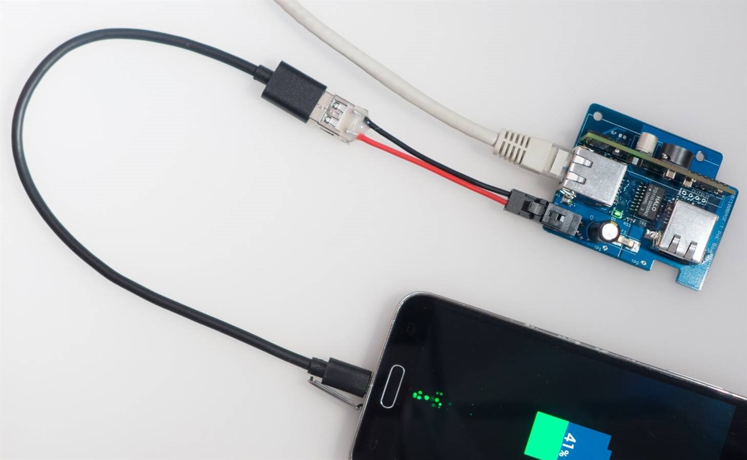
Note that the powered device doesn’t actually need to have an Ethernet connection at all. It is possible to use PoE to charge your mobile phone.

image


How do I get PoE?

Assuming standards-based PoE is required then the best way is to pick up a switch with 802.3af or 802.3at capability. In the UK for consumer use the 802.3af compliant 8-port TP-LINK TL-SG1008P costs about £50 from Amazon and provides 4 devices with up to 13W of power each, simultaneously (I have not tried this switch so it isn’t a recommendation, just a pointer to what is out there).


There are also so-called ‘PoE Injector’ adapters, also misleadingly called 2-port PoE switches sometimes. These are not great because often they are not IEEE 802.3af or 802.3at compliant and may supply power all the time; they are therefore not very green because their power cannot be shut down electronically. A true standards compliant PoE capable switch is the far better choice and doesn’t cost much as mentioned earlier, considering it can power up to four devices.


At the device end, it needs to support the same standard. If the device doesn’t support PoE then an off-the-shelf external PoE adapter can be used; it is standards compliant and taps off the supply to be used to power the device.


Building It

image

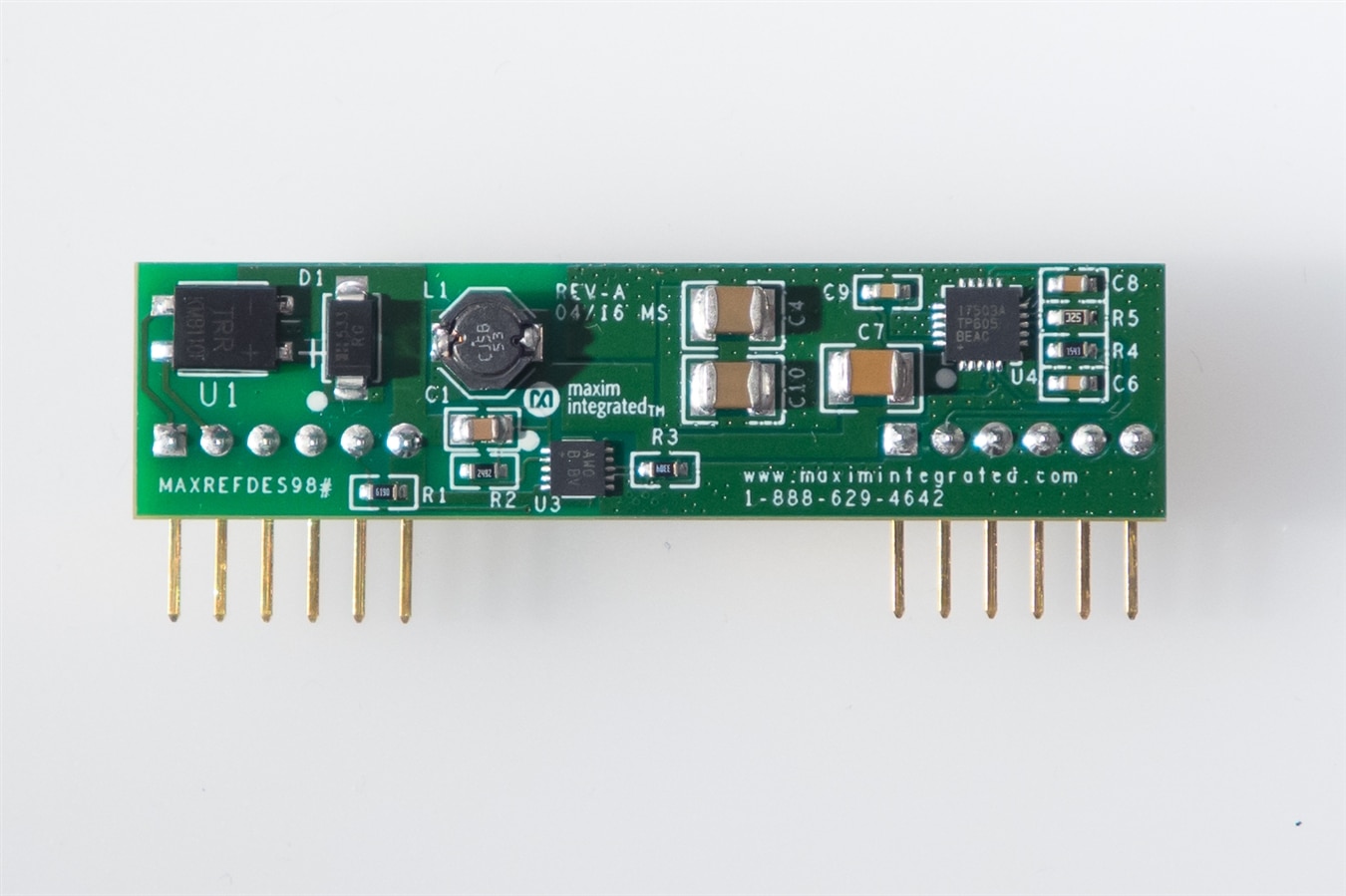
The schematic is shown below; it is really simple because most of the functionality is contained in Maxim’s MAXREFDES98MAXREFDES98 board which contains a DC-DC converter and the circuitry to handle the standards negotiation. The rest of the board mainly consists of the Ethernet transformers and connectors. Note that it would be wise to add some suppression circuitry as detailed in the original HAL-CAM blog page; I forgot to add it to this revision 1 PCB but the same method (TVS diodes) can be used as in the original blog post. At some stage I will update this blog post with revision 2 files which will correct this omission.

image


To construct this project, solder up the smallest parts first (the resistors and capacitors), ending with the largest parts. The fuse is optionally available in a socket which will fit the board but I chose to save some cost and directly solder the fuse.


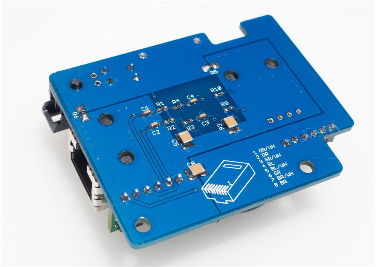
Network cables are available in short lengths but I wanted an extremely short length (a few cm) for fitting inside HAL-CAM 9001 so I used an RJ45 tool to do that. The back of the PCB has a reference indicating which color wire goes where.

image


Testing It

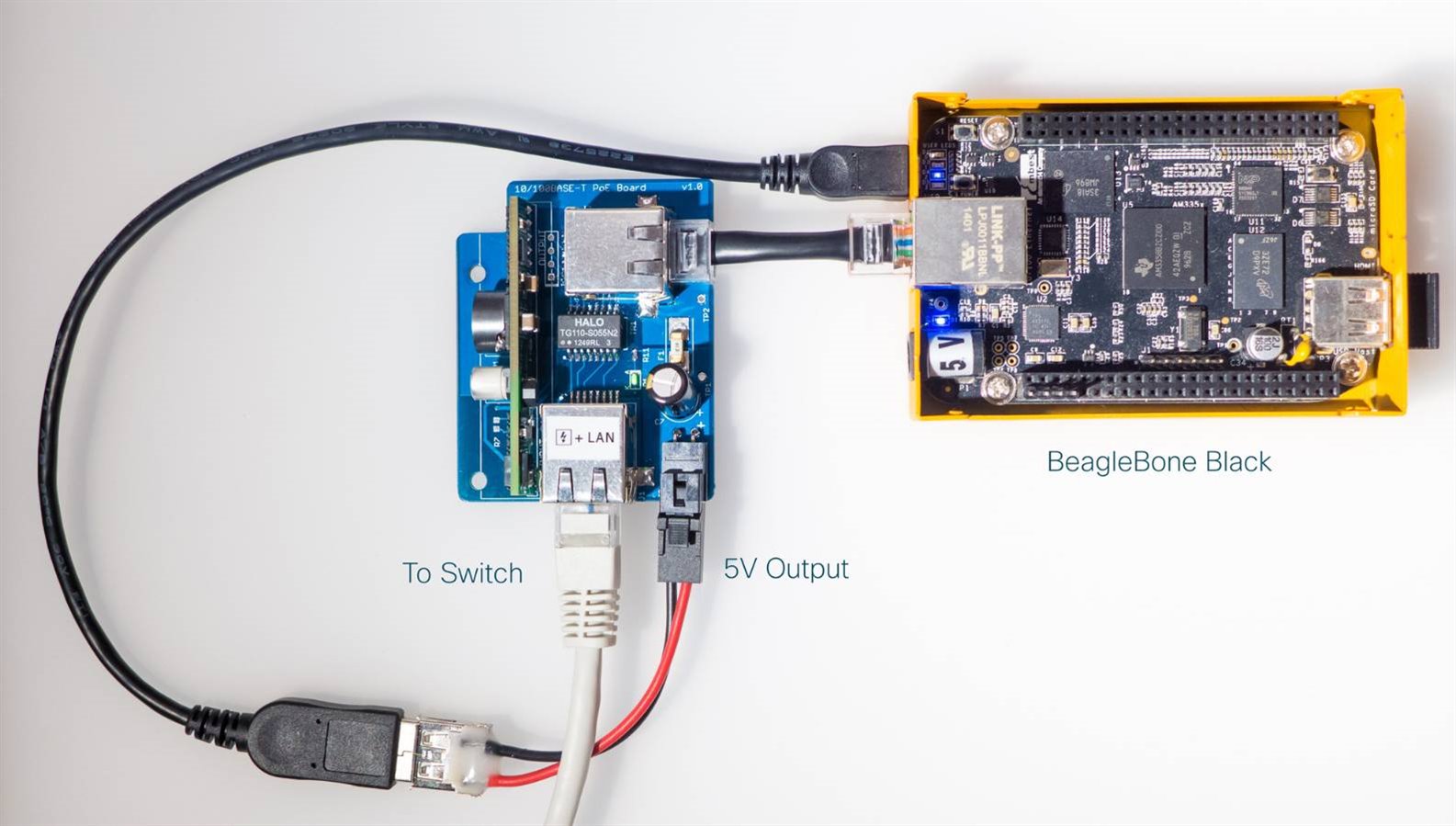
There is not much chance of error during assembly since there are so few parts in this project (the part values are in the schematic but a list of components will be published in the next few days). I connected this project via the longest length of network cable that I had (5m long) to a switch, enabled PoE on it (some switches require configuration for this) and then used a multimeter to confirm 5V was present on the output supply connector. The on-board LED was lit too, confirming that the board was receiving power. The multimeter confirmed the correct output so I proceeded to plug it into the Pi and verified that the Ethernet link came up and I had network connectivity. I can now issue a shutdown command to the Pi remotely using SSH, and then configure the switch to disable power. Whenever I want to turn the Pi on, I can configure the switch to turn on the PoE capability.


There are additional tests that should be done (such as confirm the voltage output under changing loads, verify the ‘eye diagram’ for the signals over the network cable, check for RF interference and checking throughput to see if there are any packet errors occurring). These will be done later at some stage; for now the board is functioning well enough to continue HAL-CAM 9001 development.


Summary

PoE is easy to use and it can be useful to be able to retro-fit non-PoE devices with the capability. The Maxim module makes this really easy. The PCB files are attached ready to send to a manufacturer. Note that the PCB also has some additional “features” (see photo below) which can be hack-sawed off and put aside for now (they are for unrelated mini-projects which will be documented at some later stage; feel free to guess what they are! It is not too difficult).

image


See also:


HAL-CAM 9001 – Building a New Security Camera

Attachments:
poe-export-1.zip
  • Sign in to reply

Top Comments

  • mcb1
    mcb1 over 8 years ago +4
    Nice project. It should help with that heat problem nicely ....
  • clem57
    clem57 over 8 years ago +4
    shabaz up until now, I looked at POE as redundant. But now you gave me convincing arguments to re examine. Thanks for the research. Clem
  • jw0752
    jw0752 over 8 years ago +3
    Hi Shabaz, Thanks for posting this interesting and useful build. I will be following your future refinements. John
  • shabaz
    shabaz over 8 years ago in reply to mcb1

    Hi Mark,


    Oh, excellent, this is perfect. So, it is even easier Maykol!

    • Cancel
    • Vote Up +1 Vote Down
    • Sign in to reply
    • More
    • Cancel
  • mcb1
    mcb1 over 8 years ago in reply to shabaz

    The Arduino boards have the Vin pin available.

    You can simply apply the 5v to that.


    Mark

    • Cancel
    • Vote Up +2 Vote Down
    • Sign in to reply
    • More
    • Cancel
  • shabaz
    shabaz over 8 years ago in reply to mike10

    Hi Maykol,


    You can directly use this circuit with the Arduino, however there is a complication that the Arduino usually needs 7V or slightly more, and this circuit produces 5V.

    The easiest way is to feed the power via the USB connector, which is 5V. However if you do this, then make sure that you do not connect the USB to the PC at the same time.


    An alternative approach could be to modify the circuit so that it supplies (say) 7.5V instead of 5V. This is possible by desoldering and replacing two resistors that set the regulated output voltage. The formula for this is in the MAX17503 datasheet, and they refer to resistors R3 and R4, which correspond to resistors R4 and R5 respectively in the MAXREFDES98 module (green board in the photos above). This would be a better approach if you wish to directly plug into the DC socket on the Arduino or the 7-9V supply pin. Check with a multimeter (if you don't have an oscilloscope) to ensure the output is about 7.5V before plugging in the Arduino. Also you might want to change R11 on the circuit from 470 ohms to (say) 1k ohm on the blue board, to reduce the LED brightness.

    • Cancel
    • Vote Up +1 Vote Down
    • Sign in to reply
    • More
    • Cancel
  • mike10
    mike10 over 8 years ago

    Hi Shabaz, how I coud do with arduino instead of Rapsberry?

    • Cancel
    • Vote Up 0 Vote Down
    • Sign in to reply
    • More
    • Cancel
  • shabaz
    shabaz over 8 years ago in reply to rachaelp

    Hi Rachael!


    I think you're right, as time has gone on we see some modules low cost and easy to use, so they are a great way to speed things up or to aid beginners who might want to start at some larger bite-size chunk than the ingredients, which I guess explains

    some of Arduino's popularity as you say, and the possibility exists some may not explore beyond that.

    Sometimes it is useful, for compliant stuff, like PSUs, or e.g. RF modules where if they were not used, then the antenna design could require expensive gear and hiring experts in this area. Some downsides are inflexibility and expense in this latter case, since not all modules are cheap : (


    EDIT: Also, some suppliers (especially for hobby/educational products) are guilty of information-hiding on their modules, which I think is very inappropriate for products intended for learning electronics, deliberately making it hard for people to understand beyond the module level. Their tutorials are geared for their boards only. They want people to only buy modules, and while that might make some commercial sense (I don't think it does though) it isn't the way EE has ever been taught. And hobby kits and modules and even complete products used to come with circuit diagrams..

    • Cancel
    • Vote Up +2 Vote Down
    • Sign in to reply
    • More
    • Cancel
>
element14 Community

element14 is the first online community specifically for engineers. Connect with your peers and get expert answers to your questions.

  • Members
  • Learn
  • Technologies
  • Challenges & Projects
  • Products
  • Store
  • About Us
  • Feedback & Support
  • FAQs
  • Terms of Use
  • Privacy Policy
  • Legal and Copyright Notices
  • Sitemap
  • Cookies

An Avnet Company © 2025 Premier Farnell Limited. All Rights Reserved.

Premier Farnell Ltd, registered in England and Wales (no 00876412), registered office: Farnell House, Forge Lane, Leeds LS12 2NE.

ICP 备案号 10220084.

Follow element14

  • X
  • Facebook
  • linkedin
  • YouTube