


A Linux Based Image Detecting Security Camera
Traditional security camera solutions are very good at detecting movement however these solutions are unaware about what that movement actually is. They cannot automatically tell the difference between trees moving in the air, or a car or a human.
We wanted to have a system that could identify humans and record such information; this would allow it to discriminate between uninteresting activity (such as a car driving past a road) and more interesting activity such as the presence of a stranger. Thus the HAL-CAM 9001 was born.
The camera doesn’t just output a video file; it also outputs a text file or table that contains time-stamps to indicate exactly when a human was spotted. Others may wish to identify other things such as (say) a cat. The idea is to have a searchable and readable text file that a user can quickly browse for any interesting activity.

This tutorial describes the build process. This part covers the hardware in order to have an outdoor-ready HAL-CAM 9001.
Check out the 90-second video summary (it is followed by a few minutes of video showing some of the construction that we recorded).
What is this project about?
The UK has always had a tradition of embracing the security camera. When I went to college I remember my apartment still having a black-and-white video entry system containing an image tube such as a Vidicon. This was despite the Charge Coupled Device (CCD) having been invented several decades previously; testament to how rugged and reliable valve and tube technologies could be.
Fast-forward to 2016 and there are millions of security cameras scrutinizing the public and a typical conversation during a coffee break with a colleague could well begin with “so what security cameras do you have?”; It was just this type of conversation that led to my colleague Aminder and me discussing the latest in home IP camera technology (IP cameras use a network to transfer video data) and how he was using a Raspberry Pi to operate it. We wanted to build our own low-cost open source IP security camera solution suitable for outdoor use.

HALCam: A joint project by Shabaz and Aminder
The higher performance Raspberry Pi 3 offered some interesting possibilities because it means we can run software that ordinarily needed more computing power than was possible in a low-cost outdoor unit. The Linux operating system and open source projects allow for features to be implemented that today are not present in typical home cameras, in particular the image recognition feature.
We think such a system is potentially more useful than a traditional camera because there is no need to perform a video search; it is easier to just hit Ctrl-F and search for text in a file.
Also the more we thought about it, the more we realized that what we actually wanted was a general purpose outdoor computer that could be used for other functions too. For instance if the camera is outdoors then it may as well do things like measure the outdoor temperature, or in the future open electric gates, switch on the lighting when people arrive and so on. The Pi 3 does have several built-in wireless technologies that could be useful for this.
Basic Tools
The main aim of the hardware design is have an outdoor-capable weather-resistant camera/computer. To build it we used a weatherproof plastic case and fitted everything using nuts/bolts and using acrylic or Perspex sheet as our support material inside the case to hold everything in place. The design could be replicated exactly or with modifications to suit the materials and equipment that is available. For example a 3D printer could be used instead of cutting acrylic parts.
In general some basic parts and tools that will come in handy are listed below.
- M3 (3mm) screws short and long
- 3mm thick acrylic sheet (around 300x200mm is more than enough)
- 5-minute 2-part epoxy glue (such as Araldite Rapid)
- Cutting tools, clamps
- Electric drill and drill stand (if possible), soldering iron
- Eyewear because lots of drilling and cutting is involved
Construction Overview
In essence HAL-9001 consists of a computer (the Pi 3Pi 3), the camera modulecamera module and a power supply. There are therefore three main steps to building HAL-9001;
- Building a Pi Subassembly
- Building a Camera Subassembly
- Building a Power Supply Board
There are also miscellaneous operations that need to be performed to fit and connect everything into the enclosureenclosure, such as drilling holes, fitting the heat sinkheat sink and cable glandcable gland, attaching wires and so on. These operations are varied and will be discussed throughout this tutorial. Finally there are some cosmetic operations that are optional such as painting the enclosure.
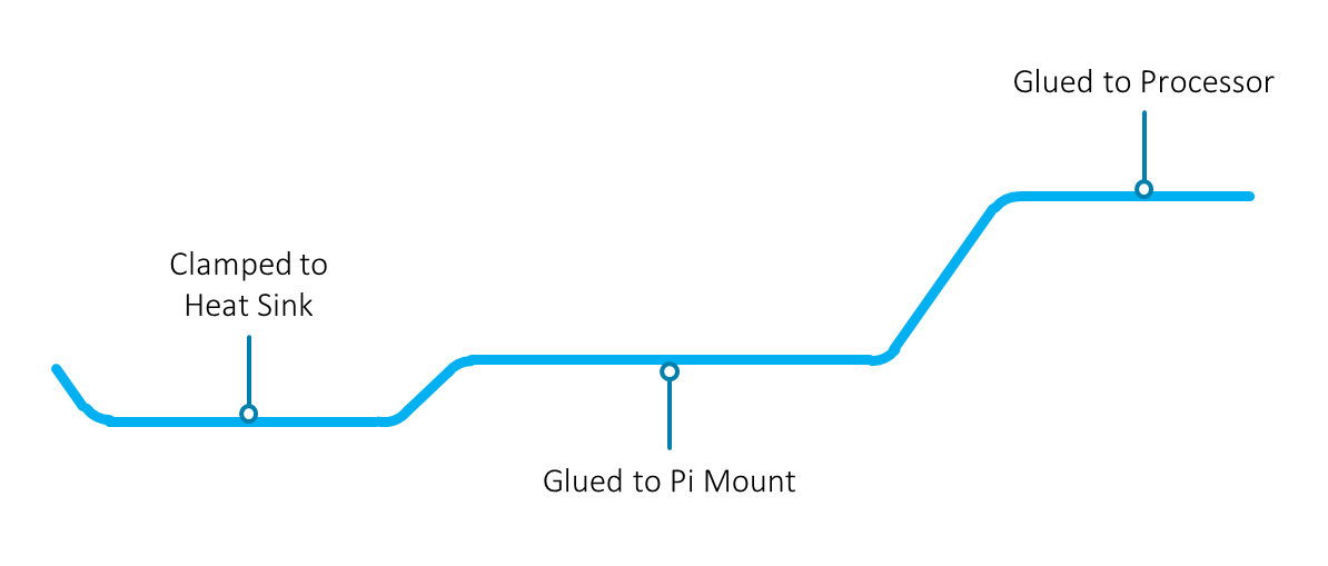
Refer to the diagram here for the terminology that will be used in this project.

Building the Pi Subassembly
The Pi Subassembly consists of a Pi 3 attached to an acrylic (Perspex) sheet called the Pi Mount using plastic spacers and a shaped heat pipeheat pipe in-between. The photo here shows it upside-down. When placed inside the case, only the underside of this will be visible.

The Pi Mount piece of acrylic is used to secure the Pi into the case using two screw holes. It also serves another purpose; it acts as a support for a heat pipe. A heat pipe is a sealed metal tube which has channels inside that pass thermal energy using a fluid. It is needed because the Pi can get hot when running intensive software. This is particularly the case when ARM ‘NEON’ computer instructions are executed repeatedly, and this is the case for one of the software libraries which is needed for this project. It is essential to keep the Pi cool inside the enclosure. Our strategy was to rely on passive air-cooling using a heat pipe and a heat sink but if you’re in a hot country this might not be enough and you may need to also consider installing a small fan.
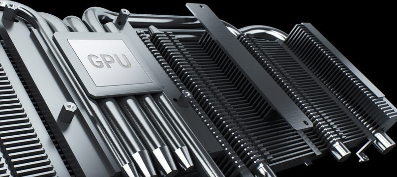
(Picture source: Asus)
Heat pipes are often seen inside PCs and the technology helps this particular project in two ways;
- It enables the heat sink to be placed at some distance on the outside of the enclosure
- It aids in serviceability because it is possible to use a screw and clamp arrangement to attach the heat pipe against the heat sink and be able to easily unscrew it whenever the Pi Subassembly needs work; something we could not easily do if the heat sink was directly attached to the Pi
In summary the heat pipe simplifies the design and eliminates the need for fans because we can use a large external heat sink.
Cut a sheet of acrylic (or make something appropriate with a 3D printer for example) such that it can be mounted 20mm above the surface of the Pi’s printed circuit board (PCB). This height is achieved by double-stacking 10mm spacers in-between.
A slot is needed for the camera flat flex cable (the earlier photo shows the flex cable in-between the Pi Mount and the Pi, but that was an experiment and it was later determined that it was easier to run the flat flex on the outside). We also made a cut-out where the 40-way Pi GPIO header pins are for slightly easier access.

All spacers and screws were plastic instead of metal; this is especially important for the lower-rightmost corner in the photo above because the Pi’s antenna is located just a few millimeters away on the PCB. Metal screws and spacers so close to the antenna will affect the communication range.
The Pi’s mount holes are less than 3mm in diameter which is awkward; it is a lot harder to find 2mm or 2.5mm spacers than 3mm ones. If it is not possible to purchase (or perhaps fabricate) appropriate spacers then an option is to do what we did; drill out the Pi’s holes to 3.2mm (this will invalidate the warranty). We used a hand-held powered drill but doing it by twisting the drill bit by hand unpowered might be less risky.

As mentioned two 10mm spacers were combined to provide 20mm height. The lower one was a press-fit spacerpress-fit spacer. The upper spacerspacer comes threaded, and we didn’t need the thread so it was drilled out with a 3.2mm bit.
The heat pipe needs bending into a suitable shape. The easiest way is to create a jig (guide) by drilling some holes in a scrap piece of wood or plastic and then push some pegs (or cut up metal rod) into the holes.

One end of the heat pipe will be glued onto the Pi’s microprocessor chip and the other end will eventually be clamped onto the heat sink.
To glue the heat pipe onto the Pi we used a thermally conductive adhesivethermally conductive adhesive. It is very strong. Clean the surfaces with isopropyl alcohol (IPA) and mix up the adhesive (it comes in two parts). Wood barbeque skewers are handy glue mixing sticks/applicators. The photo shows enough glue mixed for a dozen heat pipes so there was a lot of waste. Make sure the mix ratio is approximately correct (this was the reason for the waste; it is easier to be more accurate when mixing a larger amount) because if the ratio is incorrect or it is not thoroughly mixed then the glue will not fully harden. After the glue has been applied clamp it gently (use some rubber insulating material on the underside of the Pi to cushion the clamp). The glue takes 48 hours to dry but this can be reduced to just a few hours by turning on the Pi and installing and running the cpuburn-a53 program which will nicely heat up the chip.

Power off then loosely assemble everything together to confirm the heat pipe is still bent correctly. If some slight adjustment is needed hold the glued end and gently bend the rest of it.
Next loosely assemble the Pi Mount acrylic plate and mark off with a pen where it touches the heat pipe. Remove the Pi Mount and apply heat resistant glue (we used UHU Max Repair) and then fully screw the Pi Mount plate onto the Pi. The end result is a permanent Pi Subassembly that can be easily connected to a heat sink and is removable as an entire unit.

If the Pi ever needed replacing then the heat pipe would have to be torn off the acrylic plate and another heat pipe would need to be used. Fortunately they are low cost.
At this stage some case preparations can be performed to figure out how everything will fit inside the desired case. We used an IP65 rated box from MulticompIP65 rated box from Multicomp (the IP65 rating was lost through drilling some holes for this project! but everything can be sealed back up).
The case we used had some plastic stand-offs moulded into the inside base, and these need to be removed (for example with a Dremel tool) to get the base approximately flat.
The acrylic Pi Mount has two holes for securing it to the case however we wanted to minimize any holes to keep weather-proofing steps to a minimum. The solution we used was to create a small Threaded Plate, which was a strip of 3mm thick acrylic with metal screw thread inserts fitted.

The metal screw thread inserts are intended for injection moulded parts. To fit it into the acrylic sheet just drill a hole slightly smaller than the insert (we drilled to 3.5mm) and then set your soldering iron temperature to 180 degrees C and put the insert onto the soldering iron bit and gently push it into the acrylic. It will slowly melt its way in. When it is entirely embedded in the plastic just lightly pull to remove the iron, leaving the insert inside the plastic. It will cool rapidly and remain tightly embedded. Then the Threaded Plate can be glued inside the case at a suitable position; leave space on the HDMI connector side of the Pi, because this is where a USB-connected mSATA solid state drive (SSD) needs to fit later on.
Mark out where the heat sink cut-out is needed in the enclosure, by loosely screwing the Pi Subassembly onto the Threaded Plate and marking up with a pen. The rectangular shape can then be cut out.
Building the Camera Subassembly
The Camera Subassembly is much easier to construct. The only purpose it serves is to hold the camera in a suitable position.

We used two pieces of acrylic to achieve this. The Camera Mount piece is a friction-fit onto the protruding ends of the spacers that we used. The smaller Camera Adapter piece of acrylic serves to just provide a useful way of holding the camera. The camera has very small holes and generally feels fragile so it was preferable to just permanently attach it (using a foam pad and a tiny bit of epoxy glue at the corners) to the Camera Adapter.
To make the adapter we again used the threaded insert method since it worked so well the first time round.

The Camera Mount plate can optionally have a cut-out as shown in the photo. This was to allow the Pi’s circuit board some ‘breathing space’ and prevent it getting too hot. We used countersunk nylon screwscountersunk nylon screws because metal would be too risky so close to the PCB with the mount method that we used. Only one length of nylon screws is needed for any project because if they are too long they can be easily snipped with wire cutters.
The camera flat flex cable was routed around the outside of the plates and then taped into position. It needs to be folded as shown in order to translate the position of it from the center down to where the connector actually is.

The end result was a single convenient module consisting of the Pi Subassembly and the Camera Subassembly. It can be fitted and removed at any time from the case.
Building the Power Supply Board
The Pi will be performing a lot of computation. The Power Supply Board contains a DC-DC converterDC-DC converter which is responsible for ensuring that the Pi has a stable 5V DC supply at all times regardless of the workload. Ultimately the 5V supply will also be used to power the solid state drive (SSD), the camera and any other device attached to the Pi, so we wanted the Power Supply Board to offer around 15W of power (up to 3A at 5V). The input to the DC-DC converter is taken from the 8-wire network cable which will connect from the home to the camera location. This way just a single cable is needed to connect between home and camera, saving costs and simplifying the deployment.

Only four wires inside the cable are actually used by the Pi which means that four are available to supply DC power at a voltage suitable for the DC-DC converter input which is any value between 6-14V. We used two wires for the positive and two wires for the negative.
This scheme is not an official ‘power over Ethernet’ (PoE) scheme but to correct it a later project (now complete!) will implement standardized PoE to replace this unofficial power over Ethernet scheme which we are using.

The network cable from the outside world is connected to the Power Supply Board which actually serves two purposes. Firstly it takes the unused wires to power the DC-DC converter and supply a 5V output to the Pi. Secondly it passed through the Ethernet wires on to the Pi, but also suppressessuppresses any spikes on the wires.
The current design uses some surface mount devices (SMD) but it was assembled up using stripboard and a couple of SMD adapter boards (SOIC-8SOIC-8 and SOIC-16SOIC-16) and a normal soldering iron (2mm size bit). The SMD parts used are not overly tiny to make it easy to hand-solder. If there is interest we will design an open source PCB for this project.
The main components used are:
- DC-DC converter moduleDC-DC converter module
- NUP4201DR2 NUP4201DR2 TVS diode array
- SMBJ12ASMBJ12A TVS diode
- 2A fast-blow fuse2A fast-blow fuse
- 15uH inductor15uH inductor
- 2 x 220uF 35V capacitors220uF 35V capacitors
- 22uF 25V capacitor22uF 25V capacitor
- 1uF capacitor1uF capacitor
- 10uF capacitor10uF capacitor
- 47uF capacitor47uF capacitor
- 4.7nF capacitor4.7nF capacitor
- 2.2k 1% resistor2.2k 1% resistor
- 3.3k 1% resistor3.3k 1% resistor
- 270R resistor270R resistor
- RJ45 socketRJ45 socket

Once the board has been assembled it is recommended that some tests are done without the Pi, to check everything is ok. With no power attached use the diode check function on the multi-meter to confirm there are no shorts between any of the RJ45 pins apart from pins 4 and 5 which should be shorted (they are the DC+ pins) and pins 7 and 8 (they are the DC- pins). Also, check there is no short on the 5V output connector or test point and ground. Attach a 12V supply to the board (either directly to the test points, or using the end of a sliced up network cable), ensure it is set to a low current (about 150mA) and power it up while observing the output using a multimeter or oscilloscope. It should be very close to 5.2V. If this all works then it is likely that the board is functioning sufficiently well to proceed!

We ran some tests using resistors to simulate the Pi under different workloads. The board was tested under no load and then a medium load (1.3A) and then a high load (2.9A). The resistors of course run hot! - they were dissipating close to 15W of power.


Shown in an earlier photograph, we needed to build up a cable to connect the 5V output to the Pi. Usually people have the official Pi power supply attached to the micro USB connector. It is impractical for this project so we directly connected the 5V supply to the pins on the 40-way connector instead for a more simplified approach.

There are more than one ground pins on the 40-way connector, and there are two 5V pins. We doubled-up the wires so that both 5V pins and the two ground pins were connected to the Power Supply board. Network cable is great and low cost; we just used pairs of wire from a cut-up cat 5 network cable lying around. We also used a decent socket connectorsocket connector (i.e. not from ebay!) to try to ensure good long term contact with the pins on the 40-way connector. If you can find one, an adapter board could be used. Otherwise it is possible to directly solder to the socket connector.

At the Power Supply board end we used a Molex Ultra-Fit connector socketMolex Ultra-Fit connector socket, plugplug and crimp pinscrimp pins; it is the ideal size for either soldering on wires or using a low-cost crimp toollow-cost crimp tool.

Case Operations
We needed to do a few last things to make the case ready for this project. A hole was cut and an adapter ring called ‘Universal Filter Adapter for GoPro Hero HD 3’ was purchased from Amazon to fit it. The hole was made by drilling lots of small holes and then filing out into a larger circle.

(The case was sprayed white just for preference). Next, glue the adapter ring so that the seal is water-tight.
The heat sink had holes tapped in it. If you don’t have the tools for this, nuts and bolts could be used. Either way, some sealant will be needed on the other side if the hole goes all the way through (we tried to keep it a partial hole, but it was not feasible with the particular heat sink that we had). The heat sink is either glued to the case, or another couple of tapped holes can be used. The cable gland can be inserted and sealed too.

A network cable can now be connected. It doesn’t have to be too long because it can always be extended using back-to-back RJ45 socket adapters and then the junction can be sealed. After passing it through the cable gland, the cable needs the RJ45 plugRJ45 plug to be attached.

The Power Supply Board was fitted inside the case using a grooved piece of acrylic and a threaded spacer. The acrylic has a groove or notch cut into (or glue thinner pieces of acrylic into this shape) for the stripboard to fit in. A spacer is glued to the base of the enclosure so that the Power Supply Board can be secured with a single screw after it is pushed into the notch.
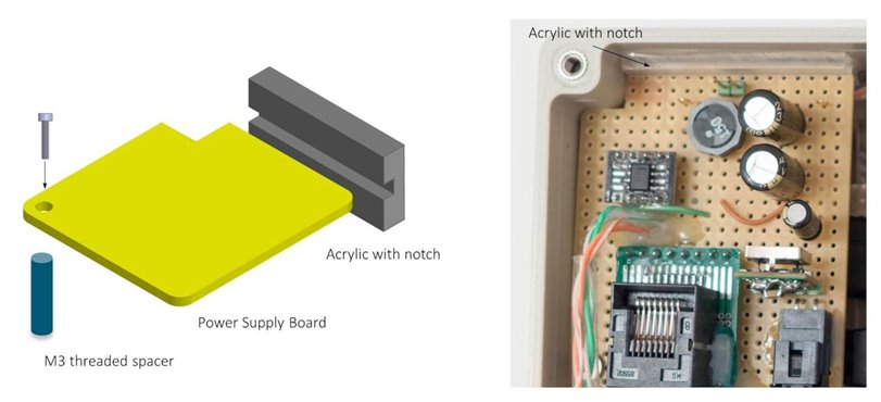
The photo below shows the insides of the completed project. Note that the solid state disk (SSD) will most likely require a ferriteferrite placed around the USB cable. This is because of electromagnetic interference (EMI) susceptibility causing the wireless signal to suffer which will cause packet loss or delay if the WiFi is enabled on the Pi. The ferrite core helps a lot although it might not completely eliminate the issue. Another option is to not install an SSD.

A ‘37mm UV(C) Digital HMC Screw-in Filter’ from Amazon was screwed onto the adapter ring. To become watertight an O-ring is needed sandwiched between the glass of the filter and the adapter ring. A '33mm x 25mm x 4mm' sized O-ring should fit, but ours had not arrived in time to physically confirm this [Edit: it arrived, and it fits well. When fully screwed, the O-ring is compressed by around 0.5-1mm, this is a guess based on visually seeing the O-ring pressed against the glass].
Trying it out
While we were finishing the design, spannerspencer suggested we adopt the red HAL eye in the final design : ) We drilled out a hole in a piece of circular plastic (it was a lens intended for an LED although we drilled out all of it and were left with just the rim), sanded it to become translucent and then glued an LED to it (we sanded flat part of the LED too, to make it easier to attach). It was tacked lightly around the camera module and directly connected to an I/O pin with a 100 ohm resistor in series.
It worked really well. From a distance it does look like HAL’s eye, and the center hole is barely visible, it is an eye pupil anyway!
It serves a great practical purpose. During power-up or in fault conditions it can be made to flash in different sequences to indicate different conditions. In normal use it would be switched off, but interestingly even switched on it had only a slight impact to the video image; very little is reflected off the glass.
More tests need to be done but we did run a brief performance test. With the case entirely closed up and the unit placed vertically as it would be deployed, the ‘cpuburn-a53’ program was run. This was at 25 degrees C ambient, indoors (i.e. no breeze). After several hours the CPU had not dropped its speed, and the temperature reported by it was hovering around the 76 degrees C mark. The external heat sink was hot! With hindsight we would go for an even larger heat sink. With such a weather resistant design HAL-CAM 9001 could even be externally water-cooled.
Summary
By adopting the heat pipe and a modular sub-assembly construction style it was possible to create a design that can be easily serviceable and should be weather resistant. We hope that people adopt parts of the design and improve on it and share their ideas, in order to have a useful outdoor image processing system. We only got as far as we did thanks to the excellent support from Farnell and Element14 who provided the hardware and valuable advice and ideas throughout.
See also:
Top Comments