element14 Community
element14 Community
    Register Log In
  • Site
  • Search
  • Log In Register
  • About Us
  • Community Hub
    Community Hub
    • What's New on element14
    • Feedback and Support
    • Benefits of Membership
    • Personal Blogs
    • Members Area
    • Achievement Levels
  • Learn
    Learn
    • Ask an Expert
    • eBooks
    • element14 presents
    • Learning Center
    • Tech Spotlight
    • STEM Academy
    • Webinars, Training and Events
    • Learning Groups
  • Technologies
    Technologies
    • 3D Printing
    • FPGA
    • Industrial Automation
    • Internet of Things
    • Power & Energy
    • Sensors
    • Technology Groups
  • Challenges & Projects
    Challenges & Projects
    • Design Challenges
    • element14 presents Projects
    • Project14
    • Arduino Projects
    • Raspberry Pi Projects
    • Project Groups
  • Products
    Products
    • Arduino
    • Avnet Boards Community
    • Dev Tools
    • Manufacturers
    • Multicomp Pro
    • Product Groups
    • Raspberry Pi
    • RoadTests & Reviews
  • Store
    Store
    • Visit Your Store
    • Choose another store...
      • Europe
      •  Austria (German)
      •  Belgium (Dutch, French)
      •  Bulgaria (Bulgarian)
      •  Czech Republic (Czech)
      •  Denmark (Danish)
      •  Estonia (Estonian)
      •  Finland (Finnish)
      •  France (French)
      •  Germany (German)
      •  Hungary (Hungarian)
      •  Ireland
      •  Israel
      •  Italy (Italian)
      •  Latvia (Latvian)
      •  
      •  Lithuania (Lithuanian)
      •  Netherlands (Dutch)
      •  Norway (Norwegian)
      •  Poland (Polish)
      •  Portugal (Portuguese)
      •  Romania (Romanian)
      •  Russia (Russian)
      •  Slovakia (Slovak)
      •  Slovenia (Slovenian)
      •  Spain (Spanish)
      •  Sweden (Swedish)
      •  Switzerland(German, French)
      •  Turkey (Turkish)
      •  United Kingdom
      • Asia Pacific
      •  Australia
      •  China
      •  Hong Kong
      •  India
      •  Korea (Korean)
      •  Malaysia
      •  New Zealand
      •  Philippines
      •  Singapore
      •  Taiwan
      •  Thailand (Thai)
      • Americas
      •  Brazil (Portuguese)
      •  Canada
      •  Mexico (Spanish)
      •  United States
      Can't find the country/region you're looking for? Visit our export site or find a local distributor.
  • Translate
  • Profile
  • Settings
Raspberry Pi Projects
  • Products
  • Raspberry Pi
  • Raspberry Pi Projects
  • More
  • Cancel
Raspberry Pi Projects
Blog Pi Alarm System - Part 2: Wireless sensors
  • Blog
  • Documents
  • Events
  • Polls
  • Members
  • Mentions
  • Sub-Groups
  • Tags
  • More
  • Cancel
  • New
Join Raspberry Pi Projects to participate - click to join for free!
  • Share
  • More
  • Cancel
Group Actions
  • Group RSS
  • More
  • Cancel
Engagement
  • Author Author: fvan
  • Date Created: 14 Feb 2014 9:48 PM Date Created
  • Views 2254 views
  • Likes 2 likes
  • Comments 5 comments
  • rpiintermediate
  • security
  • raspberrypi
  • ultimate_road_test
  • attiny
  • wireless
  • raspberry_pi_projects
  • arduino
Related
Recommended

Pi Alarm System - Part 2: Wireless sensors

fvan
fvan
14 Feb 2014

You can find part 1 here: Pi Alarm System - Part 1: Project and components description


  • Wireless Sensors
    • RF Modules
    • Prototype test
    • Triggers
      • Switch
      • Motion
    • Conclusion


Wireless Sensors


This post is focusing on the wireless sensors spread around the house in order to detect possible intrusion. In a later post, I will collect the data from these sensors with the Raspberry Pi.


RF Modules


For the communication between the remote wireless sensors and the central control unit, I used RF433MHz transmitters and a receiver.

The sensors will be equipped with a transmitter each, and the control unit with a receiver.


image

RF433MHz transmitter (left) and receiver (right)


The remote sensors need to be small, so I opted for the ATtiny85 which can easily be programmed with the Arduino IDE after installing the necessary files to recognise the hardware.


I downloaded the "arduino-tiny" ATtiny cores from https://code.google.com/p/arduino-tiny/, unzipped the contents in the Arduino/hardware folder and after restarting the Arduino IDE, the ATtiny "boards" could be selected for programming:


image

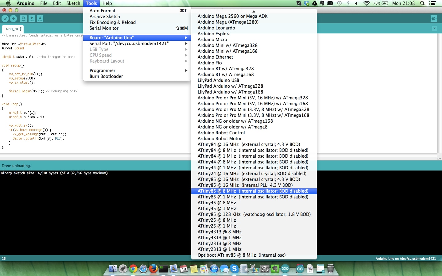
ATtiny cores available in Arduino IDE


Prototype test


I performed a quick test by hooking up an ATtiny85 to a transmitter and an Arduino Uno to a receiver. Wrote small sketches for basic one-way communication for both Tx and Rx units.


image

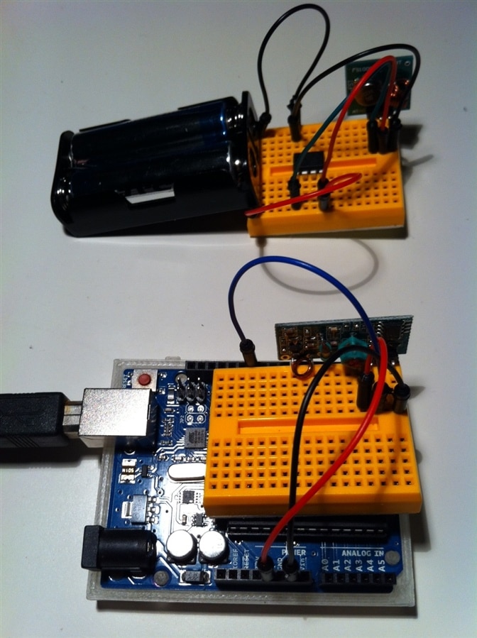
ATtiny85 transmitter (top) and Arduino Uno receiver (bottom)


The transmitter code sends an integer representing the sensor's id. The receiver code waits for data and displays it on the serial interface when available.


The goal is to have every sensor send their unique id to the receiver once they are triggered. This would be done periodically, let's say every 5 seconds.


Transmitter (ATtiny85) code:


Receiver (Arduino Uno) code:


Triggers


As mentioned in part 1, there will be two types of triggers for the remote sensors: switch or motion sensor.


Switch


The switch type of sensor can be used for doors and windows. In idle state, the switch interrupts the circuit, powering everything off.

Once the door/window is opened, the switch powers the circuit resulting in the ATtiny85 sending its sensor ID to the control unit.


image

Circuit is powered when the switch is triggered


You don't have permission to edit metadata of this video.
Edit media
x
image
Upload Preview
image


Note: the switch's functionality should be reversed (the circuit should be powered when the switch is opened).


Motion


For the second type of sensor, the motion detector should always be on. But in order to avoid having to power all components all the time, I power the ATtiny85 and RF433 transmitter using the PIR sensor's output pin. The PIR sensor's output pin goes HIGH when motion is detected. The duration of the pin's state can be changed by using one of the PIR sensor's potentiometers.


Sketch of the circuit, I hope it makes sense ... (feel free to point out any corrections and/or improvements image):


image

When the PIR detects motion, the ATtiny85 and RF433 transmitter are powered


You don't have permission to edit metadata of this video.
Edit media
x
image
Upload Preview
image


Conclusion


By adding antennas to receivers and transmitters, I was able to get reliable coverage in the entire house, even through big concrete walls.


Both sensor types work on breadboard and can now be turned into more compact PCBs.

  • Sign in to reply
  • DAB
    DAB over 11 years ago in reply to fvan

    Ok,


    I just get concerned when I see the use of ground pins in that kind of design.

    For clarity, you might want to add a note that the collector is driving the current to ground through the transistor.


    I agree  that it will work with your clarification and provide a nice current limited drive for the chip.


    DAB

    • Cancel
    • Vote Up 0 Vote Down
    • Sign in to reply
    • More
    • Cancel
  • fvan
    fvan over 11 years ago in reply to mcb1

    That's indeed a valid point. I'll have a look at the changes required to correct this.


    Thanks,

    Frederick

    • Cancel
    • Vote Up 0 Vote Down
    • Sign in to reply
    • More
    • Cancel
  • mcb1
    mcb1 over 11 years ago in reply to fvan

    Your transistor and useage is correct.


    I take it the ATtiny doesn't have a delay in the bootloader (like the Digisparks).


    The only comment I have is that this isn't 'fail to safe' that is if the battery goes flat you won't know about it.

    You could have the ATtiny85 in low power mode, and drive the interrupt to 'wake it up'.

    In between have it poll regularly to show its working.


    Good project

    Mark

    • Cancel
    • Vote Up 0 Vote Down
    • Sign in to reply
    • More
    • Cancel
  • fvan
    fvan over 11 years ago in reply to DAB

    The collector is connected to the ground pins of the load (tiny and rf433 transmitter), not to the ground of the batteries.


    This is based on following drawing I found online:


    image


    And the circuit seems to work as expected as well.

    • Cancel
    • Vote Up 0 Vote Down
    • Sign in to reply
    • More
    • Cancel
  • DAB
    DAB over 11 years ago

    I don't think your transistor will work with both the emitter and collector setting at ground level.


    DAB

    • Cancel
    • Vote Up 0 Vote Down
    • Sign in to reply
    • More
    • Cancel
element14 Community

element14 is the first online community specifically for engineers. Connect with your peers and get expert answers to your questions.

  • Members
  • Learn
  • Technologies
  • Challenges & Projects
  • Products
  • Store
  • About Us
  • Feedback & Support
  • FAQs
  • Terms of Use
  • Privacy Policy
  • Legal and Copyright Notices
  • Sitemap
  • Cookies

An Avnet Company © 2025 Premier Farnell Limited. All Rights Reserved.

Premier Farnell Ltd, registered in England and Wales (no 00876412), registered office: Farnell House, Forge Lane, Leeds LS12 2NE.

ICP 备案号 10220084.

Follow element14

  • X
  • Facebook
  • linkedin
  • YouTube