

<i think i'd rather not answer that - ed>
I recently acquired an old CooCox Embedded Pi board. This board made it possible to use a Raspberry Pi to drive Arduino Shields. The board is actually quite nice, with an STM32F103RBT6 MCU (Arm Cortex M3 core) running at 72MHz, 128KB flash, 20KB SRAM (a bit small), 12-bit ADCs, a JTAG/SWD debug port and 5V-tolerant inputs. It has standard Arduino headers, plus a set of parallel "EPI Extension Interface" headers that provide access to almost all the other pins of the STM32F103. It's a useful board. I decided to find out if I could program this board with the Arduino IDE...
HERE I HAVE COPY-PASTED MY POST FROM muman.ch - LET"S SEE IF IT WORKS (SORRY IF NOT)
What can I do with an old 'CooCox Embedded Pi' board? - 2025.06.09 |
   |
<don't forget to remove the editor's comments before publication! - ed>
<i assume this is your entry for the 'nerd of the year' competition - ed>
Blurb
I recently acquired an old CooCox Embedded Pi board <2013 is old? - ed> which had been discarded (in someone else's garage). I felt bad about throwing it away, or using if for soldering practice as someone suggested :-o (but maybe he was right...)
This CooCox board was OK, it had an STM32F103RBT6 MCU (Arm Cortex M3 core) running at 72MHz, 128KB flash, 20KB SRAM (perhaps rather small for a 32-bit MCU), 12-bit ADCs, a JTAG/SWD debug port and 5V-tolerant inputs. It has (almost) standard Arduino headers, plus a set of parallel "EPI Extension Interface" headers that provide access to many of the other STM32F103 chip's pins.
Another [what I first thought was a] nice feature is that the header pins can be either 5V or 3.3V - jumper selectable, thanks to four TXS0108E bi-directional level shifters. But there's a problem with the 3.3V supply current, see The 3.3V Power Problem, so it can really only be used with 5V shields and modules. But that's OK - a 3.3V MCU running 5V shields is also nice.
It has up to 10 x 12-bit analogue inputs (rather low impedance though). Two or three UART ports. The USB can be run as a USB CDC port (looks like a serial port to Windows). The two I²C ports run happily at 1MHz. Two SPI ports are available. Plus a CAN bus which I have not messed with yet.
The board doesn't actually have an "Embedded Raspberry Pi", you have to buy that separately and connect it to the "Pi Connector" (JP5).
<isn't 'JP' usually used for jumpers? shouldn't that be J5, not JP5? - ed>
<i think you're confusing jumpers with pullovers - matt>
I decided to find out if I could program the board with the Arduino IDE. This post details how I did it, the problems, solutions and the devastating conclusion :-) It also shows how to use Microsoft Visual Studio with the Visual Micro extension to develop Arduino projects.
Due to the totally unnecessary amount of detail <according to 'ed'>, this post may even be useful to those who are not familiar with the Arduino IDE or MS Visual Studio and the Visual Micro extension.
I had several "setbacks" en route which you can now enjoy for yourself, if you have the patience to read this voluminous exposé.
<i hope i get paid for this - ed>
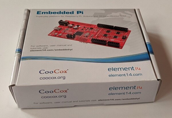
The innocent victim, still in his box.
<watch out! you may be misgendering this board - ed>
<sorry, but the last three letters of the board's name sound rather masculine to me - matt>
Who are (were) CooCox?
Actually, I don't really know. Apparently, 'CooCox' meant "Co-Operate On Cortex".
<note the subtle use of ' and " - ed>
<yes "ed" - 'matt'>
The CooCox company no longer exists, and its website (coocox.org) has disappeared silently into the ether, with no redirection - that's rather unusual.
CooCox (.org) developed not only the board, but also their own firmware to run on the board. Their firmware allowed you to use Arduino shields controlled by a connected Raspberry Pi. It had its own 'embedded real-time multi-tasking OS' called CoOS <maybe too close to 'CaOS', but that's a cool name for an OS - ed>, with libraries for many of the Arduino shields, modules and peripherals. Their code looks good, it was a nice product!
<and they developed the box too, which looks really nice - ed>
The CooCox source code is still available on github. Maybe I'll give the CoOS multitasker a try in a future post. It will probably run on all Arduino boards.
<platform-io foundations in there? - ed>
https://github.com/coocox
The board's documentation is still available on element14...
Embedded Pi User Manual
/products/devtools/technicallibrary/m/files/16214
Embedded Pi Schematic
/products/devtools/technicallibrary/m/files/16050
Pinouts
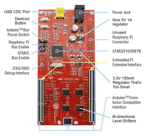
The outer pins (odd numbers) are the Arduino compatible pins.
<some numbers are 'odd'? isn't that discrimination? - ed>
The inner pins (even numbers) are the 'EPI Extended Interface' for connection to most of the remaining STM32 pins, so you have access to the additional serial ports, SPI, I²C, CAN, more analogue inputs and digital I/Os.
<i noticed that you didn't comment about 'even' numbers, that could be discrimination too - matt>
<ok, but i'm not going to define what a prime number is - ed>
The jumpers R (JP3) and S (JP4) select whether the Raspberry Pi or the STM32 controls the Arduino pins - but we will always use the "STM32 Standalone Mode" so the Raspberry Pi connector is not used, see Jumpers on the Embedded Pi board. This is a bit confusing, so for homework please study Sheet 3 of the schematic and the User Manual section 4 "Operation Modes" - there will be a written test on Monday morning.
I added some annotation for the serial ports - they change according to the USB configuration. The Arduino A4 and A5 analogue outputs are hard-wired to SDA and SCL (I2C1), but the standard Arduino A4 and A5 outputs are available on JP8 pins 10 and 12, and ADC10..13 are also on JP8. Note that D13 is either SCK or the on-board LED, so you can't use the LED if you're using SPI - but that's the same as the Arduino.
Note that the board has 4.7K pull-ups on the I²C SDA and SCL, so you don't need to fit them.
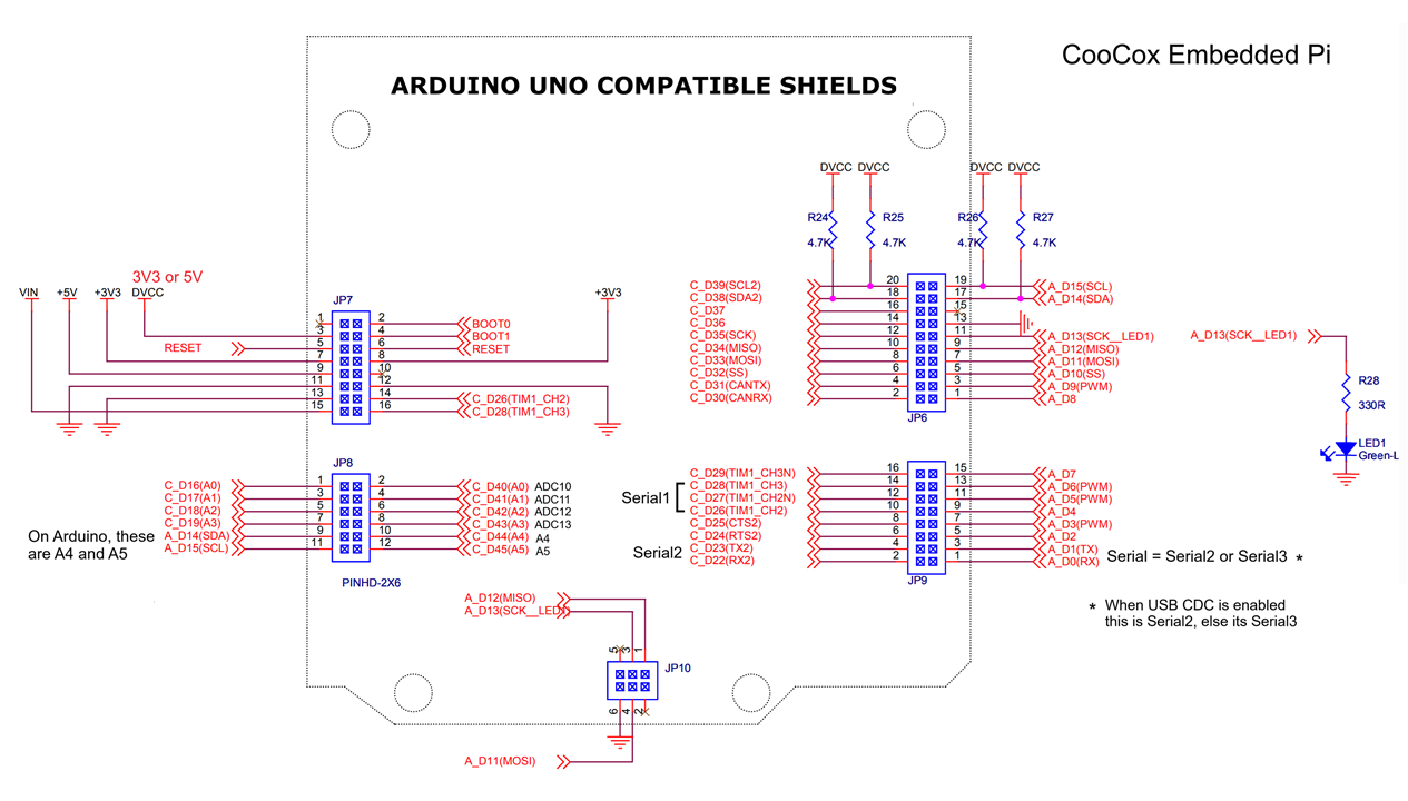
Here's the full schematic of the board
Embedded+Pi+Schematic.pdf
The STM32F103RB MCU data sheet
https://www.st.com/resource/en/datasheet/stm32f103c8.pdf
<an excellent read, for insomniacs - ed>
<if you liked that one, then check out 'The Definitive Guide to the ARM Cortex M3' by Joseph Yiu, that's only got 456 pages (in the printed edition), hours weeks months of fun! i used to keep it by my bed (until they brought out the m4, and that's got 1'500 pages :-) - matt>
Integrated development environment (IDE)
To quickly prototype MCU code in C/C++ for a new chip or module, it's nice to use a very simple development environment like the Arduino IDE (with ST-LINK debug support, of course). Other IDEs such as STM32 Cube, Microsoft Code etc, are difficult to use if you don't use them often and you have a deadline to meet, or just want to have some fun. It's advantageous not to get bogged down with the idiosyncrasies of the IDE and an 'operating system', and just concentrate on the programming task.
The Arduino and its basic software architecture of setup() and loop() makes it easy to get started, and finished. In fact, I have not found many applications that cannot be done with this very simple architecture - providing you have access to real-time interrupts from communications, inputs and timers (and you can circumvent the horrors of the shared clock configuration). Modern MCUs are so fast that you don't really need an 'operating system' or even a multi-tasker for most embedded projects.
I've been using Microsoft Visual Studio (MSVS) for desktop application development almost since it was first released. And now you can use it for embedded development too. In truth, I only use about 20% of its features. Some may say that MSVS is even more complex than Cube or Code, but for me its user-interface is more intuitive. It's more like a Windows program than a ported Linux or Mac application. And the 'OK' and 'Cancel' buttons are in the right places!
<that's a bit controversial too - ed>
MSVS is available as a free version called "Visual Studio 2022 Community Edition".
<it's now 2025, why are they still calling it MSVS 2022? - ed>
<i'll ask bill, but he's still not talking to me after that crazy party... - matt>
I know some people (like me) have a dim view of Microsoft (and Bill, especially after that party), but despite that I still think MSVS is the best development environment. I can use the same IDE to develop an entire project - the MCU embedded code (in C++ and assembler), the Windows desktop application code (usually in C#), and even the code for an associated mobile phone app - all in the same 'Solution'.
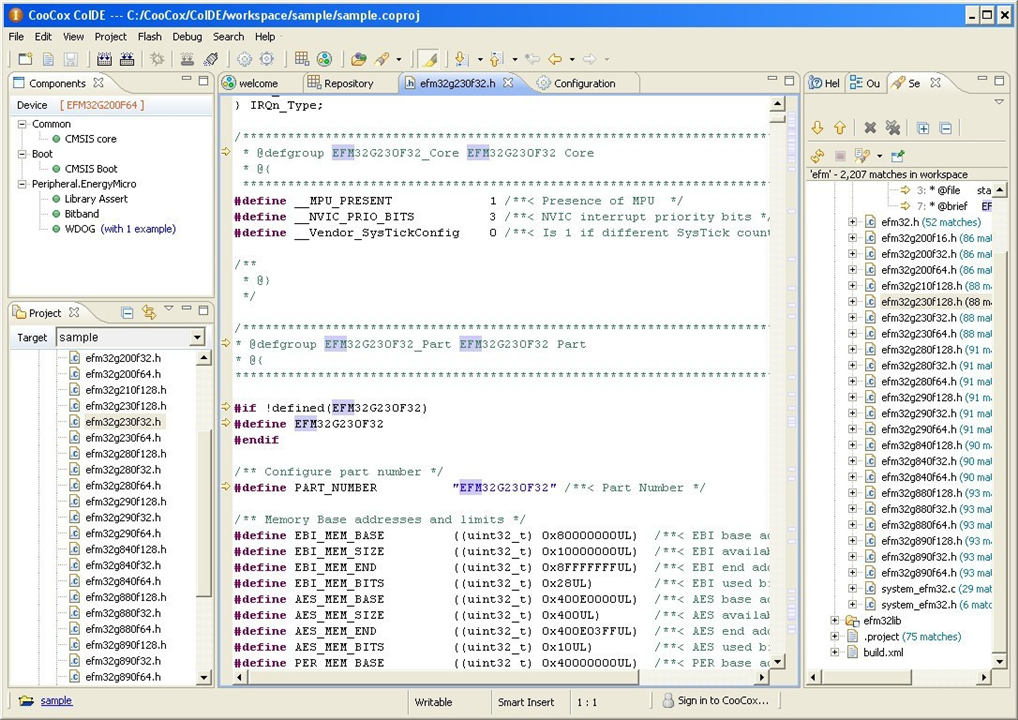
CooCox had their own Eclipse-based IDE for programming the Embedded Pi and other boards, called CoIDE. This looked quite nice, but you can't download it from the official website any more.
<phew! my hard drive is already nearly full - ed>
Using an ST-LINK/V2 programmer for downloading and debugging
I don't think the Embedded Pi had a bootloader or ISP support (In-System Programming) via USB. The USB port was not registered by Windows when I connected it to the PC, and the BOOT button didn't seem to do anything. I think it's geared up to get its program from the Raspberry Pi by ISP over the Pi connector's serial port or the ICSP (JP10). I have no idea what was running on the board when I received it.
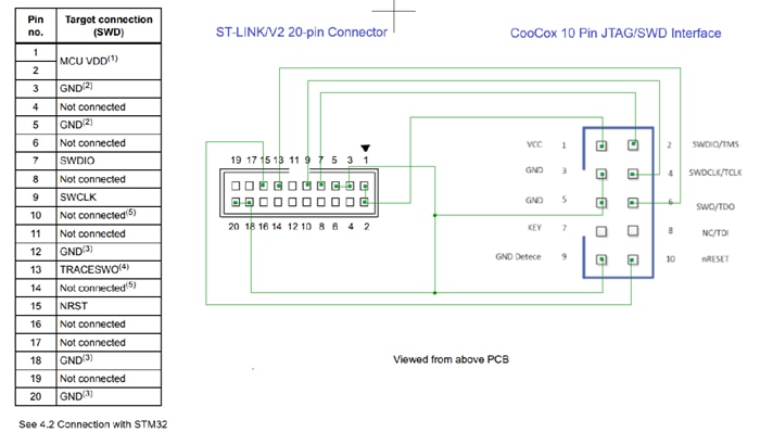
The Embedded Pi has a nice 10-pin JTAG/SWD connector (JP4) with SWD (Serial Wire Debugger) enabled by default. JTAG can be selected via solder bridge SJ1, but I stuck with SWD which has great debugging support too.
In my garage <don't you mean that dusty cardboard box under your bed - ed> <how do you know about that!? - matt>, I found an old 'ST-LINK/V2 ISOL' programmer, but I could not find the cables that came with it so I had to make an adapter.
The ISOL version is nice because it is galvanically isolated from the PC, which is great for high-voltage projects. It's a shame that my brilliant Digilent Analog Discovery 2 oscilloscope was not isolated too. I once blew up the Discovery - and my laptop's USB port - when working on a 50'000V Jacob's Ladder project. Take care where you connect the probe's GND clips! (Luckily the Discovery had only blown a tiny SMD inductor on the USB port which I unsoldered and shorted out, then it worked again. But the USB port on the laptop is permanently dead.) A future project will, of course, be an isolation module for the Digilent Analog Discovery products. I've already done the design, and I have all the parts...
Here's the ST-LINK/SWD adapter circuit (I'll probably lose it and have to make another one) ...
There are many other cheaper ST-LINK/V2 adapters available which will also work, like this one which I will try out later.
<if you can find the cables - ed>
Or you can use the ST-LINK board that comes with one of the STMicroelectronics' Nucleo-64 evaluation boards, see "Nucleo-64 STM32F103RB" below - but you'll still have to make an SWD cable.
Ready... Go!
ST-LINK/V2 ISOL user manual
https://www.st.com/resource/en/user_manual/um1075-stlinkv2-incircuit-debuggerprogrammer-for-stm8-and-stm32-stmicroelectronics.pdf
STM Cube IDE
I have the STM Cube IDE installed on my computer. I do not know if this is needed or not (drivers etc), but I suspect it may needed to use ST-LINK and select the "STM CubeProgrammer (SWD)" upload option. If this option is not available to you when selecting the "Upload method", you could try installing the ST-LINK driver:
https://www.st.com/en/development-tools/stsw-link009.html
It that doesn't work you could try installing the enormous (but free) STM Cube IDE from here:
https://www.st.com/en/development-tools/stm32cubeide.html
You could probably use the STM Cube IDE for programming the Embedded Pi. But the "learning curve" almost vertical at the beginning.
<is that vertically upwards or vertically downwards? - ed>
<no, it's more like the infinite oscillation of a lorenz attractor - matt>
Nucleo-64 STM32F103RB
<why is it called nucleo-64 when it's a 32-bit device? - ed>
<probably some kind of sales gimmick, they also have a nucleo-144 and i'm pretty sure that's not a 144-bit processor - matt>
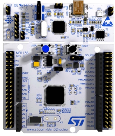
The Embedded Pi uses the same chip as the STMicroelectronics' "Nucleo-64 STM32F103RB" evaluation board, which you can pick up for less than 20 bucks! This has an integrated ST-LINK debugger/programmer, so you don't need a separate ST-LINK box. The ST-LINK part of the Nucleo can also be used stand-alone, via the SWD pin header, if you remove the jumpers on CN2 (see the User Manual PDF link below).
<maybe i should buy one of these just for the st-link bit - ed>
<yep, get 'em while you still can! - matt>
This board also has Arduino pinouts, plus all the rest of the pins too. It's very similar to the Embedded Pi board, and if you need the same chip then it's probably better to use this board - AND it has an offical STMicroelectronics "boards package" for the Arduino too, so it's very easy to use.
Another nice thing about this Nucleo board is that the Arduino pins on CN10 are evenly spaced (2.54mm), unlike the Arduino pins on CN5 - see the Infamous Arduino connector offset problem below.
https://www.st.com/resource/en/user_manual/um1724-stm32-nucleo64-boards-mb1136-stmicroelectronics.pdf
https://www.st.com/en/evaluation-tools/nucleo-f103rb.html

Serial output for logging and debugging
<don't you mean cereal? and isn't that an input, not an output? - ed>
<that depends on how many bugs you've got in your cereal output port - matt>
With Arduino programs it is common to send debug information to the 'Serial' output using Serial.print() etc, so it is displayed in the Arduino IDE's 'Cereal Monitor' window. If you configure the Embedded Pi to use USB CDC, see Serial and USB Ports, then you will see the USB port as a serial port in Window's 'Device Manager', 'Ports (COM and LPT)' group. You can then select this port in the Arduino IDE and you'll see the debug output in the 'Surreal Monitor'.
<i like it - this 'surreal monitor' idea could be a big hit! - ed>
If the USB is not configured, you will need a 'Serial to USB Converter' (3.3V version!) to convert the Embedded Pi's 3.3V serial output to USB. I use the FTDI 'TTL-232R-3V3', but there are many other similar products available.
https://ftdichip.com/products/ttl-232r-3v3/
Connect the RX pin of the adapter to the Arduino's TX pin on the Embedded Pi, JP9 pin 3. They use the right terminology - yeah!
<that could be controversial too - ed>
<huh? you connect an output (TX) to an input (RX), never RX to RX just because they have the same name, how many moonshots were lost just because of this simple error? - matt>
If using the USB to power the board, this is the only pin you need to connect - the GND goes via the USB. But if not using the USB, you will also need to connect the GND pin.
The example code in 'coocox-1.ino' uses 'Serial' for runtime logging and error messages, so you will need the 'Serial' port. Note that 'Serial' may be #defined as 'Serial1' or 'Serial2', using different pins, depending on your configuration. The example also contains the macros that I use for runtime testing, LOGERROR(), ASSERT() etc.
I usually use PuTTY to display serial data. It's much more versatile than Arduino's 'Serial Monitor', and the carriage return (\r) actually works. Arduino's 'Serial Monitor' treats carriage return as a line feed, which is VERY annoying. It means you cannot display changing data on one line because it scrolls up every time to write to it! That's something they should fix. And there's no 'clear screen' escape sequence either, but PuTTY has it.
https://www.putty.org/
<in future, i'll always use putty on windows to display surreal data - ed>
<i just remembered something - your "write only memory" (WOM) project? how did that go? - ed>
<it worked really well! not easy to test, so we didn't get the IEC certification - matt>
Steps to get the CooCox Embedded Pi board working with the Arduino IDE
Just follow these steps...

There is no Arduino "board package" available for the CooCox Embedded Pi. But STMicroelectronics has a board package that covers all their STM32 MCUs. This has a "Generic STM32F1 Series" board, with a whole set of variants which includes the "Generic F103RBTx" MCU variant. This variant is very close to what we need for the Embedded Pi.
However, the pinouts of this "Generic F103RBTx" variant are not the same as those of the Embedded Pi, so modifications are needed.
The right way to do this would be to create a new board for the Embedded Pi, based on a reference to the "Generic STM32F103 Series" board variant "Generic F103RBTx". But after a couple of days messing about with this I was unable to get it working properly, and it's not well documented. See https://arduino.github.io/arduino-cli/1.2/platform-specification/#referencing-another-core-variant-or-tool.
If anyone has managed to do this, please let me know how! (I didn't want to use STM Cube to generate the files, as they suggest, but maybe that's what I should have done.)
So I came up with a much easier way...
<don't you mean a much easier 'hack' - ed>
<yes - matt>
My hack also provides a solution to a problem that many have had over the centuries - how to create global preprocessor definitions in an Arduino sketch that can be accessed by $if statements inside add-on library files. In most IDEs there's a way to add "global #defines", like DEBUG etc., but (I think) the only way to do this with the Arduino IDE is to edit the build options in the "platform.txt" file, which affects ALL platform builds (i.e. it's not a good way). Hopefully they will add this feature soon.
C++ now has a nice preprocessor directive, #if __hasinclude("include-file-name.h"). The first place it looks for the include file is in the open Sketch directory. So if the include file is there it will load it, and if not there it will ignore it without any errors. So this statement can be used inside any library file to do almost anything you want! It does mean you have to edit the library file (rather naughty if it's not your own library), but it will have no effect if the referenced include file is not present in your Sketch, so it's quite safe. Here's what I used for the CooCox board,
#if __has_include("coocox-embedded-pi-defs.h")
#include "coocox-embedded-pi-defs.h"
#endif
<this is rather like your $IFEXIST (if file exists) and $IFINC (if file is $INCLUDED) directives you implemented in your old Instruction List Macro Assembler (S-ASM) back in 1989 - ed>
<yes, in many ways S-ASM was ahead of its time, it was an interpreted byte-code language too, like C#'s IL. i think Honeywell is still using it! - matt>
But where do you patch this code?
Once the STM32 board package has been installed (see Step 2 below), the library files for Arduino board variants can be found in the "variants" subdirectory of the board package. Hopefully you will find the build files for the STM32F103RBT6 MCU here (but you may have a different version number than 2.10.1)
C:\Users\<your-user-name>\AppData\Local\Arduino15\packages\STMicroelectronics\hardware\stm32\2.10.1\variants\STM32F1xx\F103R(8-B)T\variant_generic.h
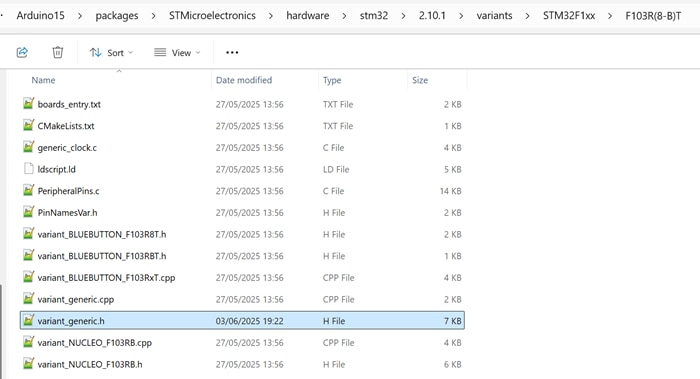
The folder also contains files for the NUCLEO_F103RB and BLUEBUTTON_F103 variants, but you can ignore those.
<that looks like a bit of a hack too - ed>
The file we need is "variant_generic.h", this contains the pin and port definitions. The relevant definitions are like this one for LED_BUILTIN, with #ifndef statements "if not defined":
// On-board LED pin number
#ifndef LED_BUILTIN
#define LED_BUILTIN PNUM_NOT_DEFINED
#endif
This means we can pre-define them, which is exactly what we do in the coocox-embedded-pi-defs.h include file.
Using the Arduino IDE
If you're not familiar with the Arduino IDE, there are many excellent tutorials on the Arduino website: https://www.arduino.cc/en/Tutorial/HomePage/
The steps are almost the same when using Microsoft Visual Studio with the Visual Micro extension, it's just the user interface that's different.
<that sounds rather suggestive, maybe tone it down a bit - ed>
1) Install the latest Arduino IDE (if you don't already have it)
https://www.arduino.cc/en/software/
2) Install the STMicroelectronics "STM32 MCU based boards" package
Each microcontroller or microcontroller (MCU) family needs different libraries to be Arduino-compatible. This is done by providing a "boards package" which contains the custom code and pin definitions for each family and each MCU.
To install a new boards package from the Arduino IDE, you need to tell it where to look. Do this by referencing the package's github json file. Add this path to the Arduino IDE's "File / Preferences... / Additional board manager URLs list"
https://github.com/stm32duino/BoardManagerFiles/raw/main/package_stmicroelectronics_index.json
Now use the Arduino IDE's "BOARDS MANAGER" to install the "STM32 MCU based boards by STMicroelectronics" boards package.
See https://docs.arduino.cc/software/ide-v2/tutorials/ide-v2-board-manager/
3) Modify the "variant_generic.h" file to access the Embedded Pi include file
Once the STM32 boards package has been installed, you will find the file we must modify here (the 2.10.1 version may be different, and use your own user name):
C:\Users\<your-user-name>\AppData\Local\Arduino15\packages\STMicroelectronics\hardware\stm32\2.10.1\variants\STM32F1xx\F103R(8-B)T\variant_generic.h
Edit this file and add these lines at the top of the file, just after the '#pragma once' line:
#if __has_include("coocox-embedded-pi-defs.h")
#include "coocox-embedded-pi-defs.h"
#endif
NOTE: You may have to re-do this if the STM32 boards package is updated or re-installed because it may overwrite the edited file. This is the only drawback with doing it this way. But you will discover this very quickly because the build will fail.
4) Connect all the hardware and check the ST-LINK/V2 adapter is working
BANG!
<isn't that a bit too much detail? - ed>
<you're right, i'll assume this step was successful to avoid possible legal complications - matt>
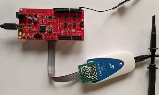
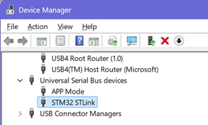
Connect the ST-LINK cable to JP4 and connect the ST-LINK box to the computer via USB.
With luck, you will see the ST-LINK/V2 device in the Device Manager:
Set the jumpers on the Embedded Pi - see Jumpers on the Embedded Pi board.
Apply power to the Embedded Pi, either via the USB connector or with a 7..12V power supply on the barrel jack.
You may also want to connect your Serial to USB converter cable.
5) Create a new Sketch and select the board and variant
'File / New Sketch', this opens a new instance of the Arduino IDE with a default Sketch name. Do 'File / Save As...' and give it a name like 'CooCox-1'. You can close the other instances of the Arduino IDE.
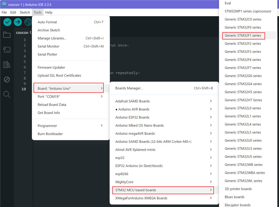
Instead of using the 'Select another board and port..' option from the combobox on the title bar, I like to do this from the 'Tools' menu.
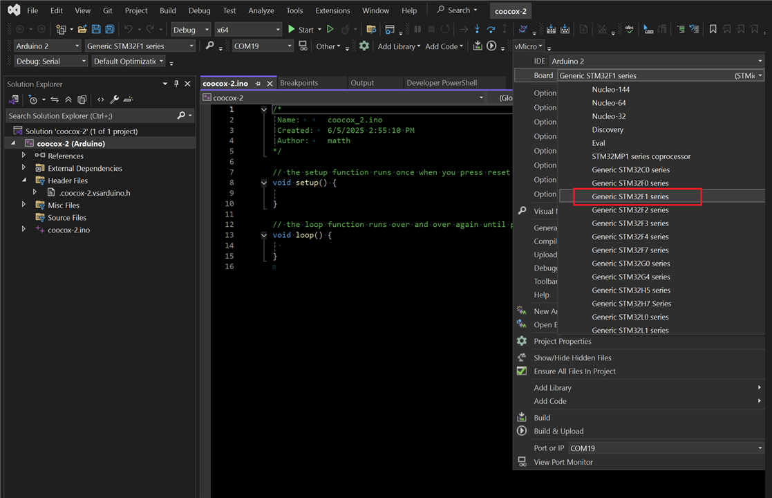
Select "STM32 MCU Boards" and choose "Generic STM32F1 Series:
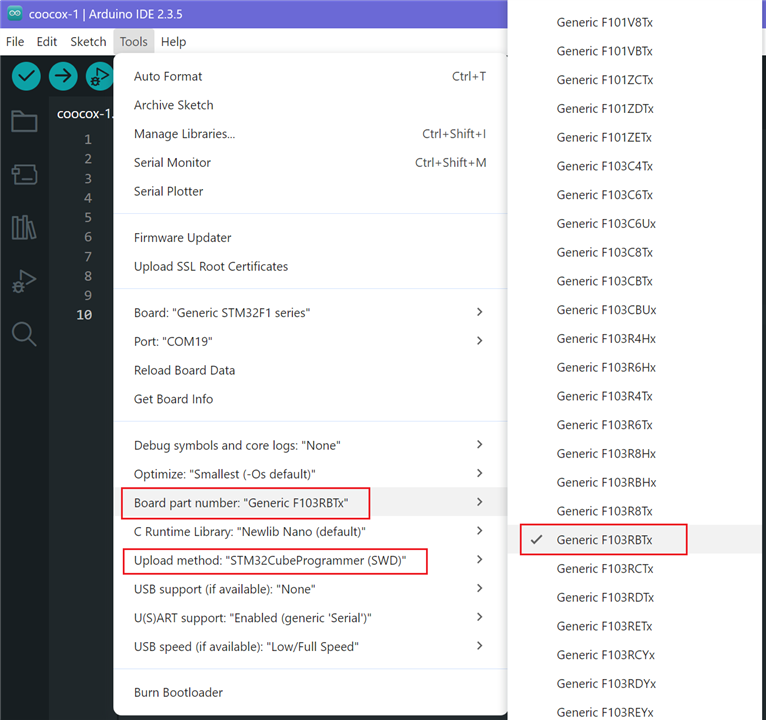
Now select the variant "Generic F103RBTx", which is called the "Board part number" in the Tools menu (don't choose the F103R8Tx by mistake).
And select "STM32CubeProgrammer (SWD)" for the "Upload method".
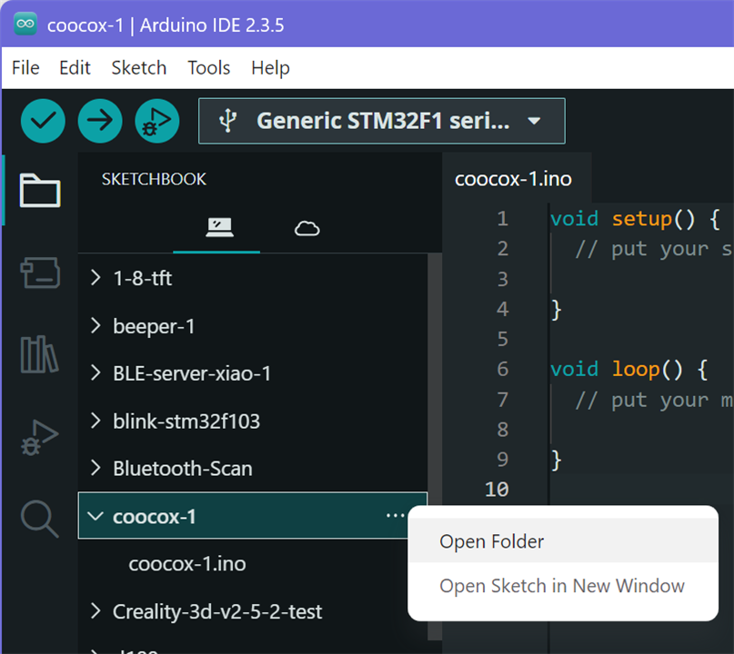
6) Add the "coocox-embedded-pi-defs.h" and "coocox-embedded-pi-pins.h" files to the Sketch
Copy these two files into the Sketch folder. They will automatically appear in the Sketchbook's file list. You can use the "..." button and choose "Open Folder".
Right-click on the file and use 'Save link as...' to download and save each file.
NOTE! For some strange reason, if you view the text file with a left-click then you will lose your place on the page when you click the 'Back' button - it goes back to the top of the page.
<to be fixed when i have time, if i can remember the javascript - matt>
<i thought you wrote it all in coffeescript - ed>
Right-click and use 'Save link as...' to download each file: coocox-embedded-pi-defs.h coocox-embedded-pi-pins.h
Or if you just want to view the files...
 coocox-embedded-pi-defs.h [Click to view/hide]
coocox-embedded-pi-pins.h [Click to view/hide]
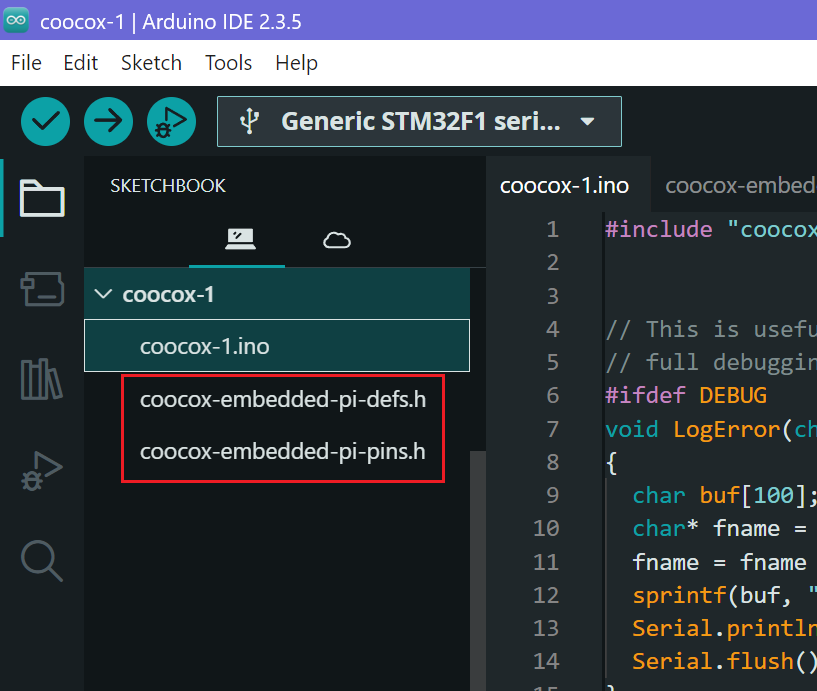
Once the two files are added, you should see them in the IDE's Sketchbook tree...
7) Add the new setup() function to initialise the CooCox board, and some code to blink the LED in loop()
Replace the "coocox1.ino" with this file, right-click and use 'Save link as...' to download the file. coocox-1.ino
The code contains configuration for an additional Serial port - see Serial and USB Ports, and a LogError() function with macros for debugging. I usually put the debug macros into a 'debug.h' file, and 'LogError()' into 'utils.cpp'.
Here's the pretty-printed code if you want to read it...
coocox-1.ino [Click to expand/collapse]
8) Download the program and see if it works
NOTE: For some reason the Arduino IDE calls loading the program into the MCU an "upload", whereas I have always thought of it as a "download" because the PC is the Master (at the top), so loading the program into the Slave MCU is a "download".
<this could start a *huge* argument! maybe delete that bit - ed>
So press the 'Upload' button to download the program, and hope for the best. The green LED should turn on and off every second.
9) If it's Friday evening, nip down the pub for a swifty
It's been hard work, you deserve a break.
<can I come too? - ed>
<sure, but only if you buy a round this time - matt>
10) If you get back in one piece, start writing some more code...
Stay up all night writing test code to exercise the analogue I/Os, serial ports, USB, I²C and SPI. To keep you awake, I've added sections below detailing how to use each feature, with examples and links.
<this didn't work for me, i crashed out after abou
Using the Visual Micro MSVS extension
Install the free "Microsoft Visual Studio 2022 Community Edition" from here
https://visualstudio.microsoft.com/vs/community/
To use MSVS with Arduino sketches and all the MCUs supported by the Arduino IDE, you must install the "Visual Micro" extension which gives you an environment with all the Arduino IDE features and all the MSVS features too. There is another (more expensive) extension called "Visual GDB" which you could try, but I haven't used it yet.
Visual Micro's website
https://www.visualmicro.com/
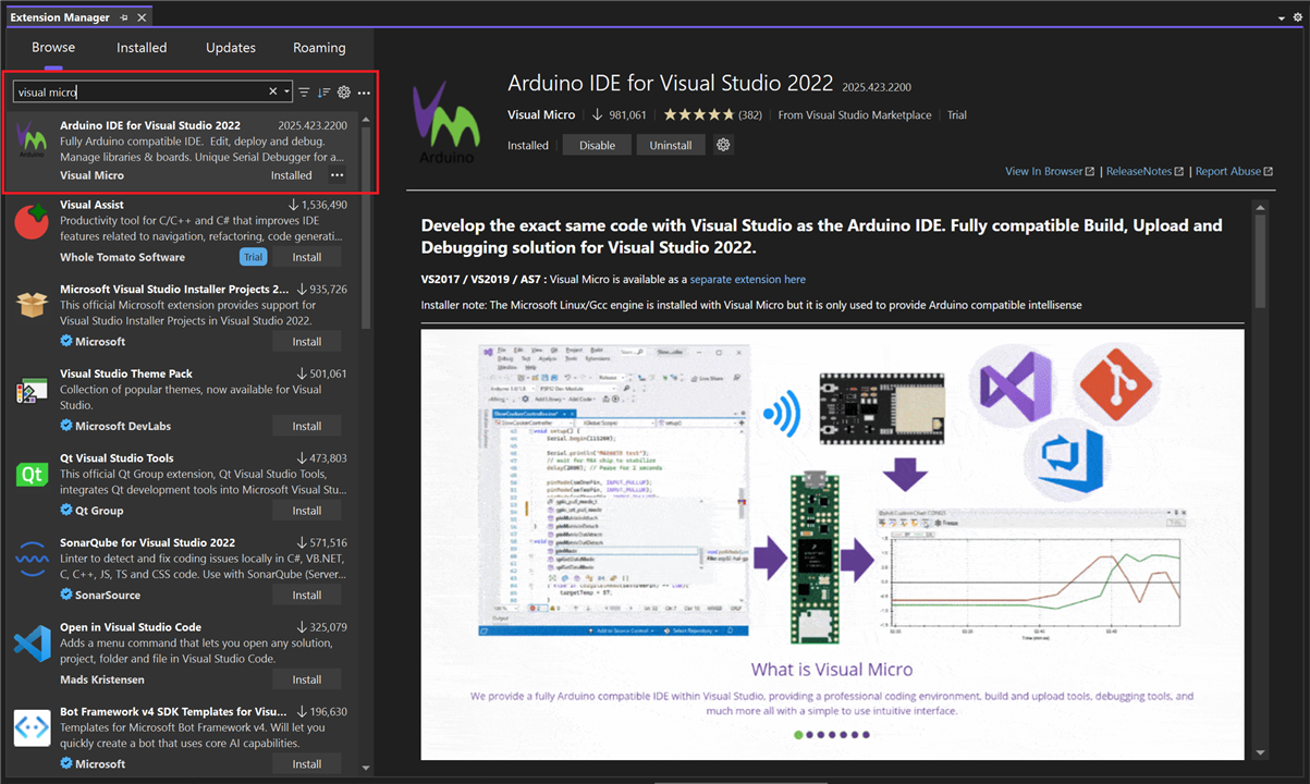
The Visual Micro extension is easily installed with the MSVS 'Extensions / Manage Extensions...' feature. Search for 'Visual Micro' and install it. After installation you will find a new 'vMicro' toolbar entry and a new 'Extensions / vMicro' menu. The menu has the same items you would see on the Arduino IDE's 'Tools' menu for the MCU, plus new entries for configuring the Visual Micro environment. I won't give a detailed description of Visual Micro because it has a great website that tells it all. So I'll mention just the bits that I find the most useful, or the most confusing.
The Visual Micro extension can be used for free for a short time (30 days?), but if you want to keep using it then you need to pay for it. It's not expensive - even I could afford it.
MSVC with Visual Micro provides a very powerful IDE, with many more features than the Arduino IDE...

Once the Visual Micro Extension has been installed using the Extension Manager
You can create a New Project and select 'Arduino Empty Project'. Call it something like 'coocox-2'.
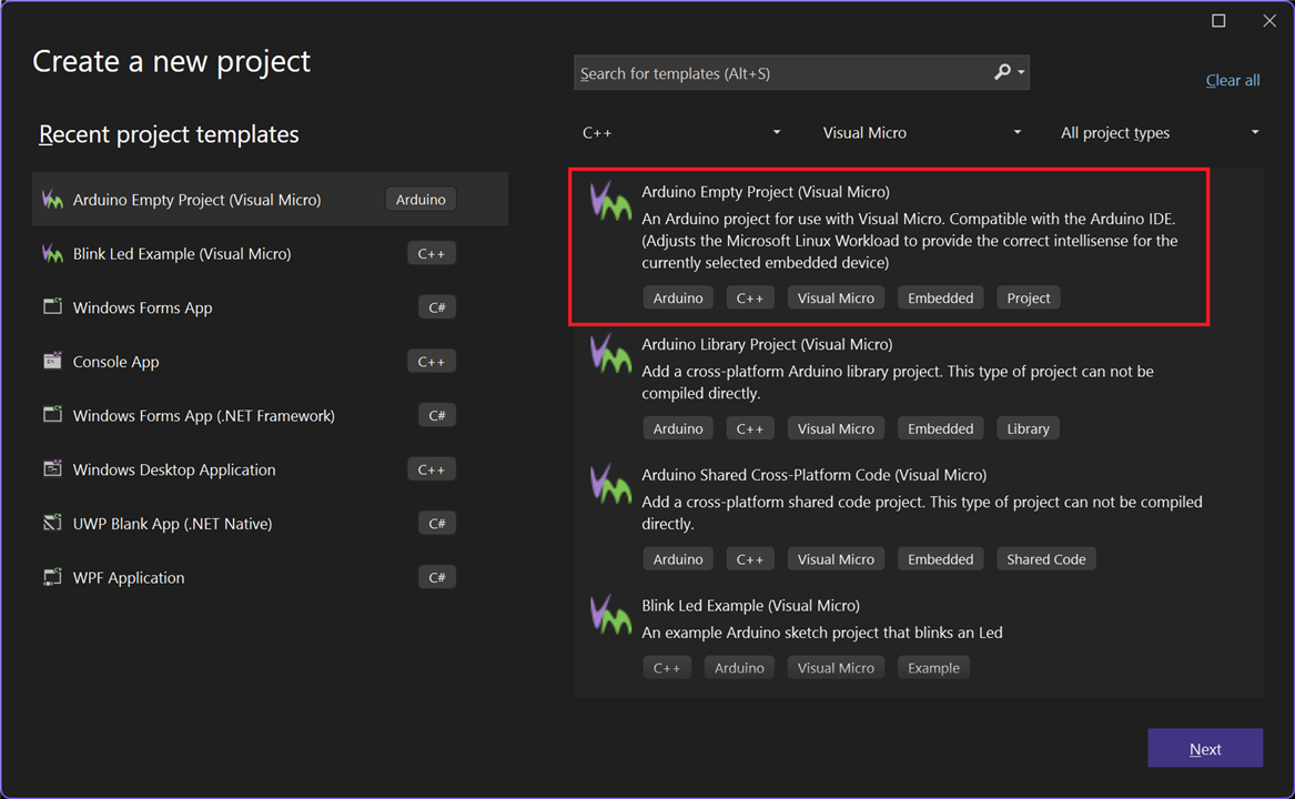
This creates an Arduino project with the default empty setup() and loop() code...
Digression: You will see in the 'Solution Explorer' tree that MSVS has created 'Header Files', 'Misc Files' and 'Source Files' folders. This is forcing you to segregate your files! I usually drag-and-drop the header file it created for Intellisense (in this case '.coocox-2.vsarduino.h') to the Project level, then delete the empty 'Header Files', 'Misc Files' and 'Source files' folders (which are real subdirectories). If you keep them, it will put all new '.c' and '.cpp' files into the 'Source Files' folder and '.h' files into 'Header Files'. I think it's better to have all the files at the top level (for a small project), sorted by name, so the .h and .cpp files are together in the files list - not in different folders!
First, if you haven't already done this using the Arduino IDE, you must install the STMicroelectronics boards package "STM32 MCU based boards by STMicroelectronics" package, see Arduino IDE Step 2. Or use vMicro's "Boards Manager", see https://www.visualmicro.com/page/User-Guide.aspx?doc=Board-Manager.html
Then modify the "variant_generic.h" file as described in Arduino Step 3.
Now select the MCU type: Open the 'vMicro' menu. You will see that the first section is the same as that on the Arduino IDE's 'Tools' menu.
Choose 'Board: Generic STM32F1 series' from the drop-down list.
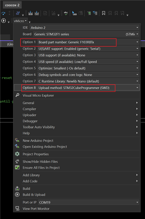
Select the board and upload method, "Option 1: Board part number: Generic F103RBTx" and "Option 8: Upload method: STM32CubeProgrammer (SWD)"...
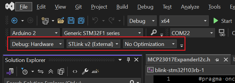
Configure the debugging from the combo-boxes, usually on the menu bars, top left. Select "Debug: Hardware", "STLINK v2 (External)" and "No optimisation" which is best for debugging. If you have your 'Serial to USB' cable connected, you can select its COM port too, so Visual Micro's Serial Monitor can be used.
Make sure the ST-LINK box is connected and the Embedded Pi has power either from the USB or the barrel jack.
Press the green triangle "Start" button to build and download the empty sketch, which should download and start running. (But it won't do anything yet.)
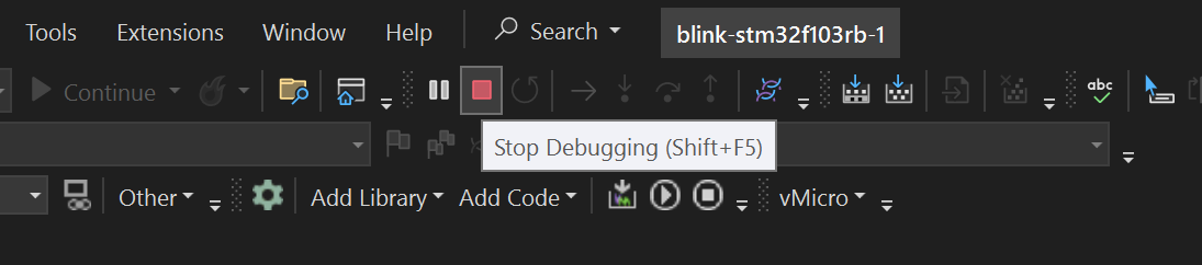
To stop the debug session so you can build and download again, you should always press the square 'Stop Debugging' button. If not, it will silently refuse to do the build.
Next, do the same things as you did for the Arduino IDE, from Step 6.
Add the "coocox-embedded-pi-defs.h" and "coocox-embedded-pi-pins.h" files to the project, and paste in the same Arduino code from "coocox-1.ino" Step 7 into the "coocox-2.ino" file.
Build and download. With luck, you will see the green LED flashing.
Now you can stay up all night again, writing test code to exercise the analogue I/Os, serial ports, USB, I²C and SPI.
<oh god, not aga
Jumpers on the Embedded Pi board
Mode Selection
The R and S jumpers (JP3 and JP4) select which signals drive the Arduino pins. There are three settings:
•R in, S out = Raspberry Pi Mode, the Arduino pins are driven by signals from the Raspberry Pi connector
•R in, S in = ST Adapter Mode,
•R out, S in = STM32 Stand Alone Mode, the STM32 drives the Arduino pins
We use "STM32 Standalone Mode", so the STM32 controls the Arduino pins directly:

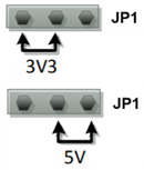
Bus Power Selection
This selects the voltage that drives the Arduino pins. It can be 3.3V or 5V. But there's a problem here, the 3.3V regulator does not have enough power to drive the pins, see The 3V3 Power Problem. I get the feeling the board was designed only for 5V shields, not 3.3V shields.
<we used jumpers for goal posts when i was a kid - ed>
<so many memories, lost in the grass - matt>
Serial and USB Ports
The Embedded Pi has three serial ports plus the USB port which behaves like a serial port when in Communications Device Class (CDC) mode. For some reason which I have not figured out yet, if USB CDC mode is enabled, then you only have two serial ports. If not using USB CDC then there are three serial ports. I would expect it to be the other way round!
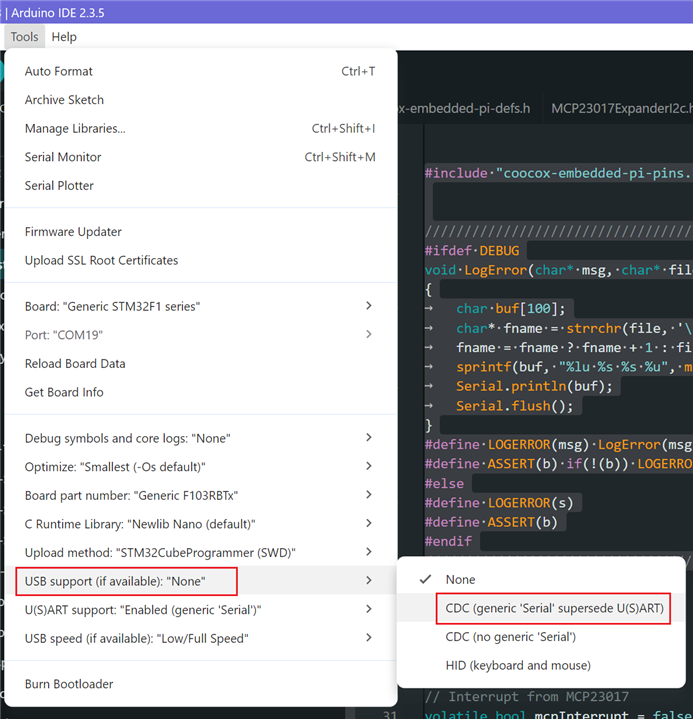
You don't have to write any code to use USB CDC, you can just enable it from the Arduino Tools menu or the MSVS vMicro menu, select "USB support > CDC (generic 'Serial' supersedes U(S)ART)".
When USB CDC is enabled
Serial = USB port
Serial1 = JP9 pins 14 (RX) and 10 (TX)
Serial2 = JP9 pins 2 (RX) and 4 (TX)
Serial3 = JP9 pins 1 (RX) and 3 (TX) - standard Arduino serial port
When USB CDC is disabled
Serial = Serial2
Serial2 = JP9 pins 1 (RX) and 3 (TX) - standard Arduino serial port
Serial1 = JP9 pins 14 (RX) and 10 (TX)
USB Discovery
For Windows to see the board as a USB device when you connect it, you must enable "USB Discovery" for the board. This is done by pulling the D+ USB signal up to 3.3V (or 5V) through a pull-up resistor. Most [slave] boards already have this fitted, but the Embedded Pi has this controlled by the USB_DISC_TRS output (PB4).
Unfortunately this pin is also MOSI for the SPI1 port, so if you want to use SPI1 and USB CDC together, then you need to modify the hardware.
<or you could use the board for soldering target practice - ed>
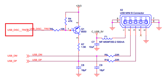
This code in setup() is used to enable USB discovery by turning on Q1 which switches in the 1.5K pull-up. The output is active low to enable the pull-up.
#ifdef USBD_USE_CDC
// Enable USB discovery, see signal USB_DISC__TRST on schematic
pinMode(USB_DISCOVERY_ENABLE, OUTPUT_OPEN_DRAIN);
digitalWrite(USB_DISCOVERY_ENABLE, 0);
#endif
You should see the Embedded Pi USB devices in the Windows Device Manager as "STMicroelectronics Virtual COM Port (COMxx)". You can now use this just like a standard serial port from your desktop application.
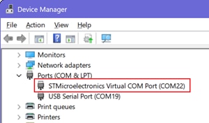
Each device has a fixed PID/VID (VID_0483 PID_5740 = STMicroelectronics Virtual COM Port, you can find this in devicehunt.com) but with a different serial number for each device (I hope). You can see this in Device Manager by right-clicking on the entry and viewing the "Properties / Details / Device Instance Path". In our case the serial number is "6D7B539A5051".
USB\VID_0483&PID_5740\6D7B539A5051
The USB port will be 'Serial', and you also have Serial1, Serial2 and Serial3 - if you need them. You can enable/disable the ports with the definitions in 'coocox-embedded-pi-defs.h':
// Patch out the serial ports which are not needed
#ifdef USBD_USE_CDC
// If USB CDC, 'Serial' is 'SerialUSB'
// Serial1, Serial2 and Serial3 are available
// Serial3 is the Arduino serial port, JP9 pins 1 (RX) and 3 (TX)
#define ENABLE_HWSERIAL1 // Serial1, J9 pins 14 (RX) and 10 (TX)
#define ENABLE_HWSERIAL2 // Serial2, J9 pins 2 (RX) and 4 (TX)
#define ENABLE_HWSERIAL3 // Serial3, JP9 pins 1 (RX) and 3 (TX)
#else
// If no USB CDC, the Arduino 'Serial' is 'Serial2', JP9 pins 1 (RX) and 3 (TX)
// Serial1 is available
#define ENABLE_HWSERIAL1 // Serial1, JP9 pins 14 (RX) and 10 (TX)
// Serial2 is enabled by default, JP9 pins 1 (RX) and 3 (TX)
// Serial3 cannot be used
#endif
#endif
If you add this code to your loop() function, you can see which port is which by connecting the RX pin of your Serial to USB Converter to the TX output of each port. Refer to the Pinouts.
void loop()
{
Serial.println("Serial"); // this is the USB port
Serial1.println("Serial1"); // TX on JP9 pin 10
Serial2.println("Serial2"); // TX on JP9 pin 4
Serial3.println("Serial3"); // TX on JP9 pin 3 <- patch out this line if not using USB CDC
delay(1000);
}
To view the output, use Arduino's 'Serial Monitor', vMicros's 'View Port Monitor', or PuTTY (etc).
If you write a desktop application to talk to the Embedded Pi as a COM port, you will need some code to find the correct COM port, or allow the user to choose one. Here's some example C# code for Windows which creates a list of matching USB COM ports that it finds by VID, PID and optional serial number.
List<string> FindMatchingSerialPorts(string vendorId, string productId, string serialNumber = null) [Click to expand/collapse]
I²C and SPI ports
The Embedded Pi contains two I²C ports and two SPI ports. You can see which pins to use from the Pinouts diagram. To test these you'll need suitable modules or chips.
NOTE! If you want to use the chip's SPI2 port, then you CANNOT use the on-board LED, because LED_BUILTIN and SCK2 are on the same pin! (PB13).
<or you could use the board for target practice - ed>
To check the I²C ports are working you can use the example code developed for the MCP23017 16-bit I/O Expander chip (if you have one), or the PCF8574 8-bit I/O Expander. This code has been tested on the Embedded Pi board.
There's also example code for several I²C Temperature Sensors.
For SPI, you could try this code for two common SPI digital potentiometers and an MCP3202 ADC chip with an SPI interface, if you happen to have one of these in that box under the bed. This is code I recently modified from some of my old projects. It's all been tested on the Embedded Pi and seems to work.
You will find the code for LOGERROR() and ASSERT() in 'coocox.ino', aee Aduino Step 7. These are very useful during development.
MCP41xxx42xxxDigiPot.h single/dual 8-bit digital potentiometer
MCP4xxxDigiPot.h single 7 or 8-bit digital potentiometer
MCP3202.h 12-bit ADC (you don't need this - the STM32 already has many 12-bit ADC inputs)
Analogue inputs, not quite Arduino standard
Analogue inputs A0..A3 are on the usual Arduino pins.
But the Arduino A4 and A5 pins are used for the I²C port I2C1. A4 and A5 are available on the Extension Interface JP8, pins 10 and 12.
The other four analogue inputs ADC10/11/12/13 are on Extension Interface JP8, pins 2/4/6/8.
To test the analogue inputs, you can play with thermistors and platinum temperature sensors, or just connect a potentiometer between +3.3V and GND with the wiper connected to an analogue input. Or if you want to be really fancy, you could connect a digital potentiometer and control it via I2C or SPI, see above.
Using resistive and analogue temperature sensors is described in Temperature Sensors, with example source code and calibration procedures.
Or you could play with Infrared Reflective Sensors.
Digital I/Os and input interrupts
A good example of interrupt handling can be found in the Mains A/C Voltage Zero Crossing Detector post.
Note that this project uses mains voltages and is DANGEROUS if you lack experience, see Disclaimer.
<even reading matt's "code" can be dangerous! - ed>
The 3.3V power problem, and non-standard use of the Arduino VIN pin
The data sheet says, "Compatible with both 5V and 3.3V Arduino shields, selectable with jumpers", but this is not really true.
From the schematic diagram you can see that the 3.3V regulator is an LPC2985-33DBVR, which can supply max. 150mA.
But the STM32F103RBT6 chip itself needs up to 150mA.
This leaves nothing for 3.3V shields and peripherals!
If using 5V shields there's plenty of power from the 5V regulator, an NCP1117ST50T3G which can provide 5V at up to 1A.
So if you are using a 3.3V shield, 150mA is probably not be enough!
The board's power supply circuit is exactly the same as the Arduino Uno, even using the same two chips. But in the Uno, the 3V3 regulator only supplies the 3V3 pin and the comparator input, it was not designed to power the shields. The Uno documentation states, "the 3V3 pin can typically supply up to 50mA of current".
The original Uno schematic, the Embedded Pi's power circuit is the same
Arduino_Uno_Rev3-schematic.pdf
LPC2985-33DBVR data sheet
https://www.ti.com/lit/ds/symlink/lp2985.pdf
NCP1117ST50T3G data sheet
https://www.onsemi.com/download/data-sheet/pdf/ncp1117-d.pdf
I think this is a design error.
If you need more than a few 10's of milliamps for a 3.3V shield then you will need a bigger 3.3V regulator!
The only solution is to unsolder the tiny 3.3V regulator and replace it with one that can supply up to 1A - but there's not enough space on the board for a bigger regulator.
If you're making your own Shield prototype (as I am), then you could put a new 3.3V regulator on the Shield board: Unsolder the LPC2985-33DBVR 3.3V regulator and leave the space empty. Provide a new 3.3V regulator, with its input from the +5V on JP7 pin 9 (you could also connect pins 9 and 10 together and use both), and its output connected to the two +3.3V pins 7 and 8 on JP7. But then the Embedded Pi won't work without the Shield connected.
Another way could be to connect your new 3.3V regulator to JP1. This has 5V for the regulator input and the 3.3V connection for the regulator output. You could make a small board that plugs onto JP1, with your regulator mounted on it and a new JP1 jumper... But where do you connect the GND? Damn, it won't work.
VIN Pin - Danger!
On an Arduino, VIN is connected to the barrel connector supply, so it's a 7..12V output if the barrel connector is used, or a 7..12V input from an external power supply if the barrel connector is not used. You would normally connect it to the external power supply via a Schottky diode (e.g. 1N5819), in case someone plugs a power supply into the barrel connector.
On the Embedded Pi, the VIN pin is actually a 3.3V or 5V output from an onboard regulator, depending on the "Arduino bus power switch" jumper JP1 position (3.3V or 5V).
It would seriously damage the Embedded Pi board if VIN was connected to an external 7..12V power supply!
Some shields, like motor controller shields, have their own power connection and also supply power to the Arduino via the VIN pin. This would certainly blow up your Embedded Pi board! Even if it survived the VIN problem.
<isn't that a good business plan? they'd have to buy another CooCox board, and that would increase sales - ed>
<yes, but it would also increase dissatisfaction, which has a higher entropy - matt>
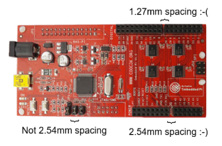
Prototype shields and the infamous Arduino connector offset problem
The most annoying thing about the Arduino is that the two larger pin-headers are not aligned on a 2.54mm (0.1 inch) grid. On the JP6 side of the Embedded Pi, pins D8..D13..SDA..SCL are on two headers which are spaced apart by 1.27mm instead of 2.54mm. The pins are therefore not aligned with the holes of a 2.5mm board, so you cannot solder pin headers onto a standard 2.54mm breadboard and plug it onto the Arduino! I presume they did this so you have to buy their proprietary Arduino prototyping boards instead of using any old 2.54mm board.
So, being Arduino compatible, the Embedded Pi has the same problem. And the jumper pins are also not aligned to 2.54mm, so you can't connect those to a 2.54mm board either.
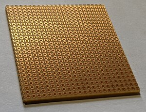
This kind of 2.54mm drilled board cannot be used with the Arduino because the holes do not align with some of the Arduino's pins :-(
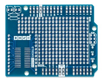
I needed a prototype board with access to all the pins, both the Arduino pins and the Embedded Pi's Extended Interface pins, and the ICSP connector too.
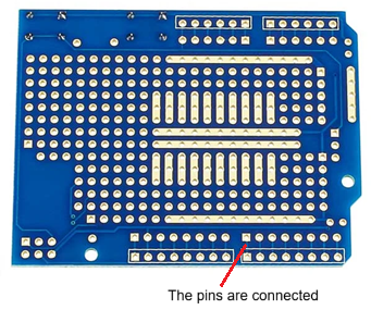
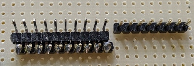
Luckily, I found that some of the Arduino shield prototype boards do have two rows of pins, and they plug perfectly onto the Embedded Pi :-)
Unfortunately, both rows of adjacent pins are connected together! :-(
All the boards I found have tracks connecting adjacent pins, but thin tracks can be cut with a knife or a Dremel rotary tool, or perhaps with a manually-controlled CNC3018 machine. The tracks are on the underside, so you won't see the cuts when it's fitted.
You should leave the 5V, 3V3 and GND pins connected, since they are also connected on the Embedded Pi board.
The official Arduino boards have thick soldered tracks, which cannot easily be cut. Do not use these!
There is another way to solve the problem. I often plug an Arduino upside-down onto pin headers on a prototype board. You can create the offset pin headers by soldering a 90º header to a standard pin header to move it by 1.27mm, as seen here...
Strange program crash due to gcc compiler bug?
I had a very annoying problem which had me stumped for a while. After downloading, the program just hung. It did not even finish running setup(). Without a good debugger this would have been very hard to find.
What I had done was write a function that should have returned 'bool', but instead it returned nothing. This was not detected by the compiler - I think that's a bug in the compiler.
Here's a stripped down version of what I did. It compiles without an error.
bool func() { }
void setup() { func(); }
void loop { }
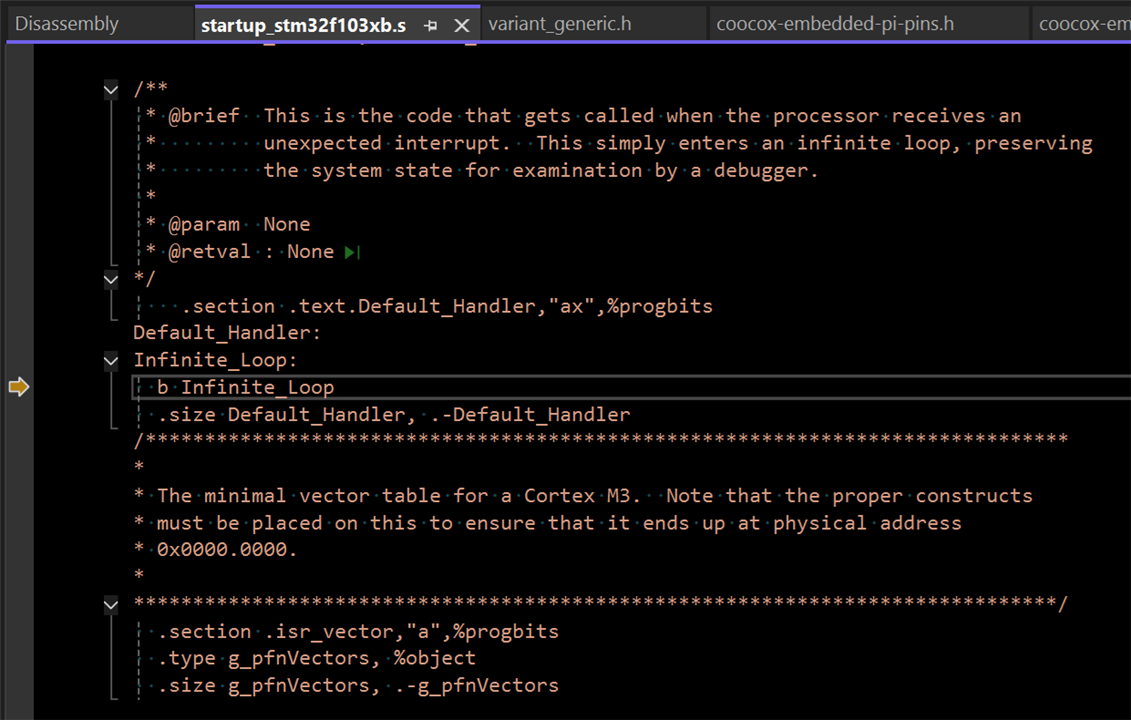
If you run this, it never returns from func(). The reason is that the compiler realized something was wrong and added the 'undefined' instruction udf #255 to the generated code. But why didn't it generate a build error?
I only managed to find this using MSVS's 'Disassembly' view, which shows the assembler code generated by the compiler.

<zzzz - ed>
When udf #255 executes, it ends up in the STM32's default interrupt handler, and nothing else works.
It would be hard to find this bug if you're only using Arduino Serial.print() statements. I wonder how many people have been stuck with this one?
Conclusion
After all this work, I've finally decided that he was right... I should have used the board for 'soldering practice'.
<i think he really meant 'target practice' - ed>
Maybe I could use it for a project that needs the additional analogue inputs and I/O ports. If it has enough RAM - 20KB is rather small for a 32-bit MCU.
<but that's still bigger than the 8KB you had for that 3d printer board with an atmega 2560 about 10 years ago, and you did a lot with that - ed>
For example, my 'Electron Tube Tester' project. This will have three or four MCU-controlled variable-voltage power supplies (0..50V for the heaters, 0..1000V for the anode and screen grids, and -100..+10V for the control grids), with current and voltage monitoring, (too) many safety features, and lots of MOSFETs :-)
But if I really wanted to use this [old] MCU, I'd probably go for a "Nucleo-64 STM32F103RB" evaluation board with built-in ST-LINK instead.
References
STM32F103RB MCU data sheet
https://www.st.com/resource/en/datasheet/stm32f103c8.pdf
CooCox Embedded Pi links on element14
/products/roadtest/rt/roadtests/369/embedded_pi
/products/devtools/product-pages/w/documents/21091/a-triple-play-platform-for-raspberry-pi-arduino-and-32-bit-embedded-arm
CooCox source on github
https://github.com/coocox
CooCox IDE - CoIDE
https://kb.segger.com/CooCox_CoIDE
Microsoft Visual Studio 2022 Community Edition (MSVS)
https://visualstudio.microsoft.com/vs/community/
Visual Micro Extension (download using MSVS "Extension Manager")
https://www.visualmicro.com/

Visual GDB. I haven't tried it, but it looks good. Expensive though, I'll stick with Visual Micro.
https://visualgdb.com/
TXS0108E 8-bit bi-directional level shifter data sheet
https://www.ti.com/lit/ds/symlink/txs0108e.pdf


