


Table of Contents
Introduction
The XR-1000 is an easy-to-build, hopefully easy-to-use, Python-operated, open-source/open-hardware hackable eXperimental Robot just slightly bigger than a coke can.

The photo above shows a prototype with the keypad on perf-board, but a printed circuit board (PCB) exists too. This is what the entire XR-1000 robot looks like logically:

In this short blog post, the ‘solved problems’ in the diagram above get solved : )
So far, two topics have been covered; the motor control board, and a control keypad. Both use a Pi Pico microcontroller. The motor control board can be used standalone; it accepts serial UART input in a Logo-like language, and it also has a single button for playing any hard-coded test sequence to exercise the motors. The motion control board is programmed in C for high performance.
The 16-key control keypad board can send commands to the motor control board using the serial UART. The user doesn’t need to know the Logo-like language, and instead can just press buttons to move the robot forward or rotate any desired angle, and the control keypad will store the instructions until the user hits the RUN command sequence. The keypad control board is programmed in Python for flexibility.
The control keypad has built-in speech capability, so there’s no need for a display, the user can hear useful prompts and feedback as they press the buttons.
Since this robot is supposed to be flexible, you could swap out the control keypad board for a more sophisticated processing board if desired. Or, you could continue to extend the electronics by attaching peripheral boards to the control keypad board connectors.
In this blog post, I wanted to discuss an ultra-simple chassis and combine the two boards (they connect together with a single flat-flex cable on top, and attach the motors so that the robot can move!
The chassis requires no special tools to make because it is made at a PCB factory. All that needs to be done is to gently fold out the tabs to convert it from a flat-pack into a 3-dimensional shape. Everything can then be screwed onto it. All connections are plugged-in, so there’s no time spent soldering connections either.

There’s not a lot of text to this blog post, because it’s fairly trivial to screw everything together and the photos explain it all. At the end of it, you’ll have a system that you can control with the keypad.
Assembling the Chassis
A single piece of aluminium forms the chassis. The Gerber files for it are on GitHub, and they can be uploaded to any PCB manufacturer site that supports aluminium PCBs. I used JLC PCB, and the cost was $16 plus shipping, for five boards, i.e. just over $3 per chassis.
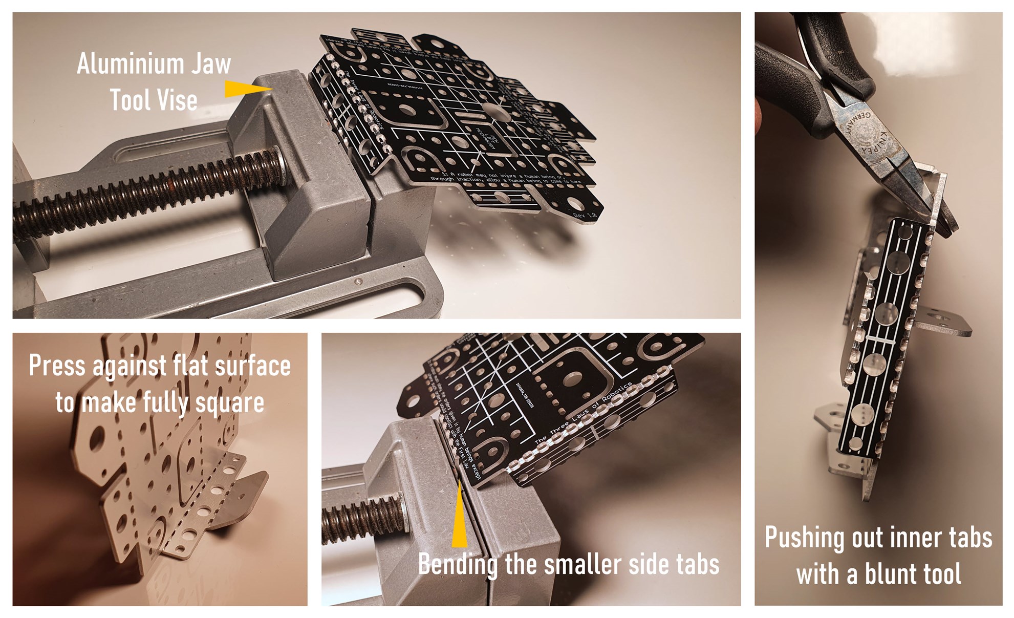
The photos above show how to fold the chassis. The top insulated surface of the aluminium PCB will crack when each fold is made, and the fold can only be made once; if you overshoot and then try to unfold, then it’s likely to significantly weaken the aluminium. A single, gentle bend is fine, and there will be sufficient strength for the robot. If you do accidentally overshoot, it could be possible to recover the strength by putting epoxy resin or another filler into the holes along the fold, however, I have not tried that and don’t know if it would be successful. It’s best to purchase a few spare aluminium PCBs and use one or two to practice the folding strategy and sequence that the folds will occur. My approach was to make 80-degree folds in the tool vise where a 90-degree fold was required and then finish off the fold by gently pressing against a flat surface for the remaining 10 degrees.
The tab which will hold the ball wheel was not initially folded fully square, because it is adjusted later so that the entire chassis is perfectly horizontal when all the wheels are fitted.
The photo below shows one of the motors fitted. The motors, wheels and ball wheel, are all from AliExpress. The relevant search terms are listed below.
| Item | Qty | AliExpress Search Term |
| Motor | 3 | Stepping Gear Motor DC5V 6V 2-phase 4-wire Gearbox |
| Wheel | 2 | D-hole rubber wheel for N20 Motor |
| Ball transfer unit (Ball Wheel) | 1 | Official Quality Robotic Universal Wheel/Ball 3PI Caster |
The motors come with a built-in gearbox. I used the 50:1 ratio version here.
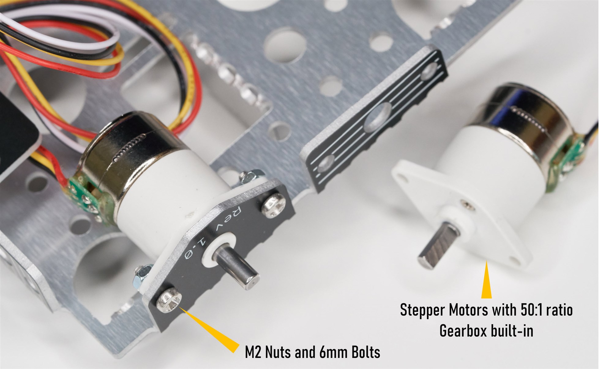
The wheels just push onto the motor/gearbox axle. It’s worth buying a few spare wheels, to find the ones which have a good friction fit. Glue could be used for the wheels, but I didn’t find it necessary.
Next, I attached the ball wheel.
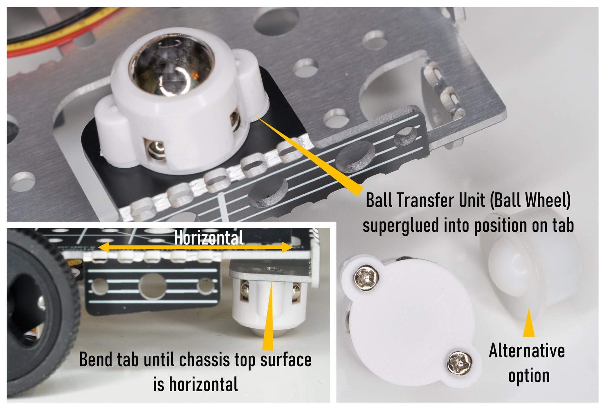
The battery needs the correct connector on it; it’s a JST PH connector, you can buy wires from AliExpress with the connector already attached, but you may need to extract the crimps from the plastic housing and swap them around if the red and black wires are not in the correct positions.
A single-cell LiPo or Li-Ion battery is used, but make sure it has a built-in protection circuit.

The photo below shows the underside of the robot. I don’t have a good way of securing the battery; double-sided sticky foam pads could be used. The two motors and the connectors were labeled A and B, for left and right wheels respectively.
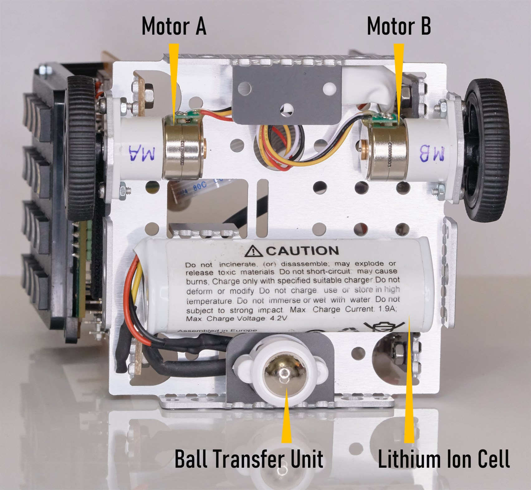
Protecting the wiring for the motors and battery, from the sharp edges of the chassis, is essential. I used heatshrink sleeving to achieve this, but perhaps a cut rubber grommet could be used.

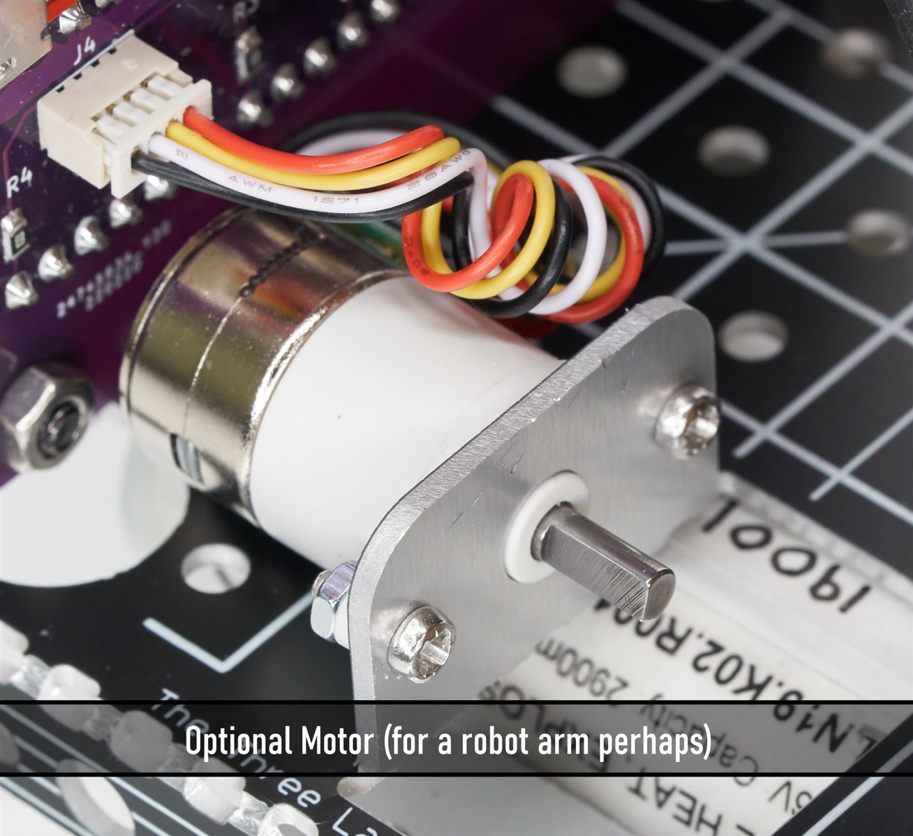
There is space on the chassis for an optional motor. I fitted the motor now since the motor control board would need to be unscrewed to retrofit the motor later. I used a motor with a 150:1 ratio gearbox instead of the 50:1 ratio used for the two wheels. There is no purpose for this motor currently.
Attaching the Control Boards
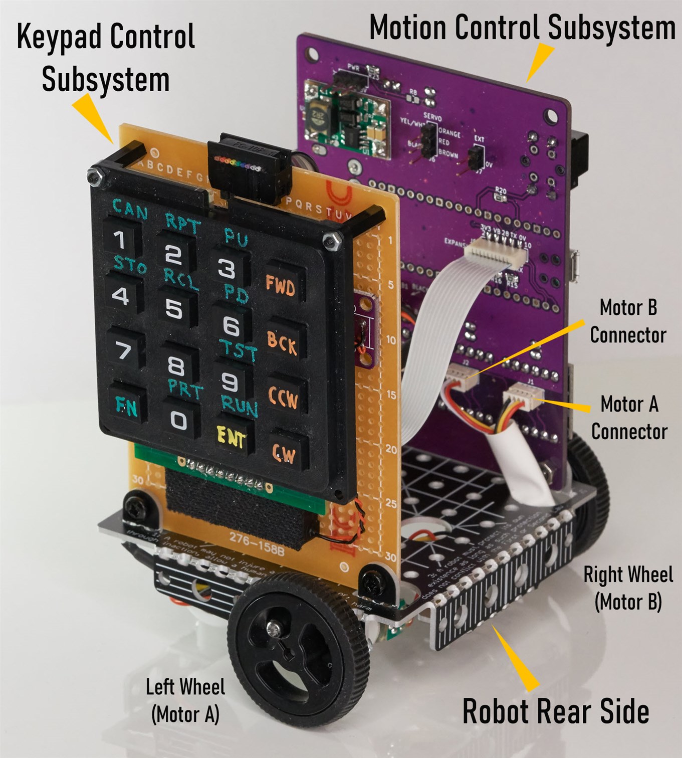
At a minimum, the Motion Control Subsystem board is required because it contains the motor drivers. I attached that and the Keypad Control Subsystem board. The latter attaches to the motion board using a single flat flex cable.
Each board is attached using two M3 nuts and 6mm bolts.
Here is a view from the keypad side. The keypad board is a prototype on perf-board, but the blog post for it has the link to Gerber files for a proper PCB for it.
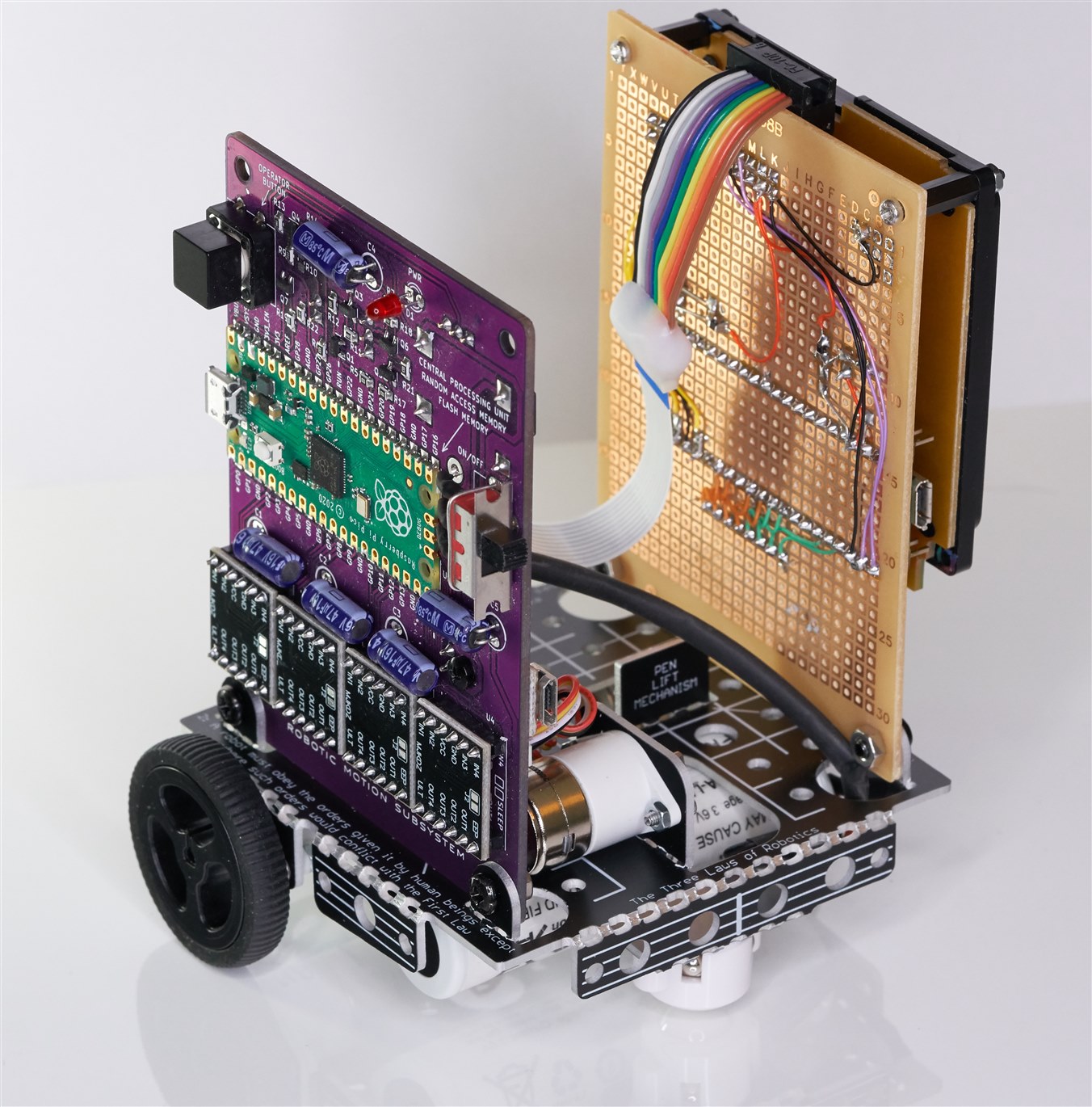
The photo below shows the motion control board with its four stepper motor controllers. The PCB version doesn’t require the ribbon cable visible in the photo below, it uses just a flat flex cable. Power from the battery arrives at the motion control board and is passed to the keypad board across that flat flex cable, along with a few data connections.
Using It
See the keypad control blog post to understand how the keypad is used to operate the motors. The assembled robot worked the first time, although the code has a bug that mixes up left and right motions. If you tell the robot to turn left, it turns right, and vice-versa : ) I’ll fix the code for that at some point, it’s an easy bug to resolve.
To use the robot, just slide the power switch on the motion control board, and begin pressing buttons on the keypad to program it : ) Finally press the RUN key combination (press the FN button, and then press the ENT button which doubles as a RUN button). It’s very easy to use, based on the labeling on the keypad above. I tested with a couple of kids, they found it easy to instruct the robot to move in a square shape and so on.
Ideas
The chassis has placeholder areas for additional electromechanical stuff. The keypad control board has connections for additional peripherals, such as sensors, or it could be replaced with a completely different, more powerful processing unit.
I hope to build a pen mechanism so that the XR-1000 can function like a turtle robot. A standard servo fits the chassis, for performing the pen lift operation. The motion control board has a connection for a servo.
It would also be interesting to try to construct a robot arm since a single axis is already present with the optional motor. A fourth motor can be controlled to add another axis.
It would also be interesting to build an exterior shell for the robot; there are holes for screwing that onto the chassis. Perhaps a 3D printer could be used to construct the shell or more aluminium panels could be used.
Thanks for reading!
Top Comments