element14 Community
element14 Community
    Register Log In
  • Site
  • Search
  • Log In Register
  • Community Hub
    Community Hub
    • What's New on element14
    • Feedback and Support
    • Benefits of Membership
    • Personal Blogs
    • Members Area
    • Achievement Levels
  • Learn
    Learn
    • Ask an Expert
    • eBooks
    • element14 presents
    • Learning Center
    • Tech Spotlight
    • STEM Academy
    • Webinars, Training and Events
    • Learning Groups
  • Technologies
    Technologies
    • 3D Printing
    • FPGA
    • Industrial Automation
    • Internet of Things
    • Power & Energy
    • Sensors
    • Technology Groups
  • Challenges & Projects
    Challenges & Projects
    • Design Challenges
    • element14 presents Projects
    • Project14
    • Arduino Projects
    • Raspberry Pi Projects
    • Project Groups
  • Products
    Products
    • Arduino
    • Avnet & Tria Boards Community
    • Dev Tools
    • Manufacturers
    • Multicomp Pro
    • Product Groups
    • Raspberry Pi
    • RoadTests & Reviews
  • About Us
    About the element14 Community
  • Store
    Store
    • Visit Your Store
    • Choose another store...
      • Europe
      •  Austria (German)
      •  Belgium (Dutch, French)
      •  Bulgaria (Bulgarian)
      •  Czech Republic (Czech)
      •  Denmark (Danish)
      •  Estonia (Estonian)
      •  Finland (Finnish)
      •  France (French)
      •  Germany (German)
      •  Hungary (Hungarian)
      •  Ireland
      •  Israel
      •  Italy (Italian)
      •  Latvia (Latvian)
      •  
      •  Lithuania (Lithuanian)
      •  Netherlands (Dutch)
      •  Norway (Norwegian)
      •  Poland (Polish)
      •  Portugal (Portuguese)
      •  Romania (Romanian)
      •  Russia (Russian)
      •  Slovakia (Slovak)
      •  Slovenia (Slovenian)
      •  Spain (Spanish)
      •  Sweden (Swedish)
      •  Switzerland(German, French)
      •  Turkey (Turkish)
      •  United Kingdom
      • Asia Pacific
      •  Australia
      •  China
      •  Hong Kong
      •  India
      •  Japan
      •  Korea (Korean)
      •  Malaysia
      •  New Zealand
      •  Philippines
      •  Singapore
      •  Taiwan
      •  Thailand (Thai)
      •  Vietnam
      • Americas
      •  Brazil (Portuguese)
      •  Canada
      •  Mexico (Spanish)
      •  United States
      Can't find the country/region you're looking for? Visit our export site or find a local distributor.
  • Translate
  • Profile
  • Settings
Raspberry Pi Projects
  • Products
  • Raspberry Pi
  • Raspberry Pi Projects
  • More
  • Cancel
Raspberry Pi Projects
Documents Building a Low Power Compact LCD Display
  • Blog
  • Documents
  • Events
  • Polls
  • Members
  • Mentions
  • Sub-Groups
  • Tags
  • More
  • Cancel
  • New
Join Raspberry Pi Projects to participate - click to join for free!
Actions
  • Share
  • More
  • Cancel
Engagement
  • Author Author: shabaz
  • Date Created: 22 Apr 2016 4:41 PM Date Created
  • Last Updated Last Updated: 10 May 2021 6:52 PM
  • Views 14599 views
  • Likes 20 likes
  • Comments 51 comments
Related
Recommended

Building a Low Power Compact LCD Display

(Note: For a follow-up project which uses a larger screen, click here:Building a 3.5 Digit Low Power LCD Module  )

image

Introduction

Sometimes a really simple, low power display is needed. A lot of information can be shown on even a 7-segment display!


This LCD board project could be useful for such purposes. The three 7-segment digits (and two decimal places total, between the digits) can show percentages, hexadecimal values, voltages and current readings. Plenty of characters can be represented too.


Up to four of these displays can be connected to a single I2C bus so (for example) a power supply project could use one display for voltage and another for current, for two channels. To save costs for smaller projects a single display could be used to show more than one item of information using  a button press or periodic cycling of data on the display.

image


The reflective LCD that is used has no backlight but has very good contrast and in tests had excellent visibility even in dim light. The power consumption is extremely low and this makes it ideal for portable projects which might need to run for years on batteries without charging. The entire bill-of-materials is less than £5GBP (or lower if multiple displays are purchased).

The schematic and plot (gerber) files and source code is attached to this post. I had 20 PCBs made for less than the cost of a pizza.

image

As a quick test I tried it using a Raspberry Pi just counting up from 0.0 to 99.9. With very little effort it would be possible to use it to display Pi stats – for example temperature, or the IP address (one byte at a time) upon start-up. It is easy to get any script to write to the display from the command line.

You don't have permission to edit metadata of this video.
Edit media
x
image
Upload Preview
image


Features Summary

  • 3.3V or 5V capable
  • Ultra-low current consumption (24uA at 3.3V)
  • Extremely compact; 32x21mm
  • Just a 4 wire connection; I2C Interface, 0V and VDD (3.3V or 5V)
  • Individually addressable segments for alphanumeric and other symbol use
  • Quick to assemble; less than a dozen parts
  • Low cost; about £5GBP in quantities of 1


Parts List

RefCodeMnfr Part #DescriptionQtyGBP Each
LCD118389301838930LCD-S301C31TRLCD-S301C31TRLCD 3-digit11.85
U124004602400460PCF85176TLCD Driver11.18
C317591221759122MC0603B104K500CT100N 0603 x7r10.01
R1, R320733492073349MCMR06X1002FTLMCMR06X1002FTL10K Res 060320.01
R2, R4, R5D.N.F.00.00
R6, R793319729331972MC0063W060352K7MC0063W060352K72.7k Res 060320.01
J1159341515934152211S-06G2211S-06GSIL header 6-way10.26
Optional177848177848D01-99012 01PCB pin sockets 12-way21.18
Optional229985622998560552-2-15-01-21-27-10-00552-2-15-01-21-27-10-0PCB pin sockets (alternative)240.07


Additional components for 5V operation

RefCodeMnfr Part #DescriptionQtyGBP Each
U223143722314372TPS70925DBVTTPS70925DBVTLDO 2.5V Voltage Regulator10.82
C119073431907343C1608X7R1C105K080AC1u 0603 X7R10.04
C217355421735542GRM21BR71E225KA73LGRM21BR71E225KA73L2.2u 0805 X7R10.24


How it Works

There are different types of LCDs, but in general they require an alternating current (AC) signal to turn on segments. Some use a square wave, others require multiple voltage levels in order to achieve high segment density with low pin count through multiplexing.

The particular LCD chosen requires a square wave, and has the benefit of providing high contrast digits. Reflective displays offer high contrast but have the disadvantage that they are opaque from the underside and cannot be lit from behind so require either ambient light to be visible or a side light.


Some microcontrollers feature LCD driving capability but there is a classic integrated circuit from NXP that is useful to offload the task from microcontrollers and allow the use of an I2C bus for interfacing. That IC is the PCF8576 which has been around for more than two decades. NXP have a more recent IC called PCF85176 (it appears to be backwards-compatible) and that is the one used for this project because it has very low power consumption requirements and a higher speed I2C bus capability than its predecessor.

Nothing else is needed apart from a few resistors and capacitors.


The LCD needs a few volts peak voltage in order to function. For 5V operation a linear regulator provides the lower voltage to run the LCD.


Building It
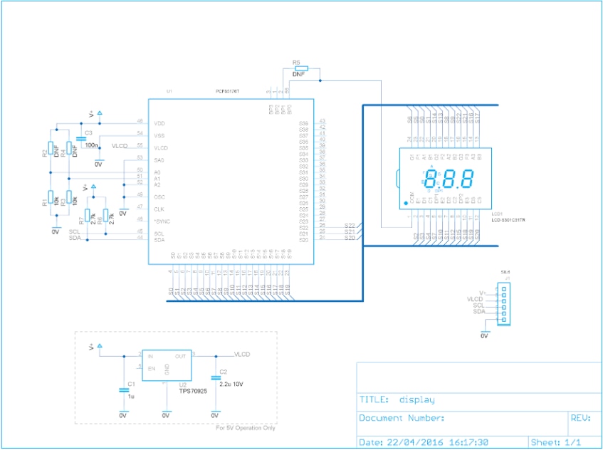
image

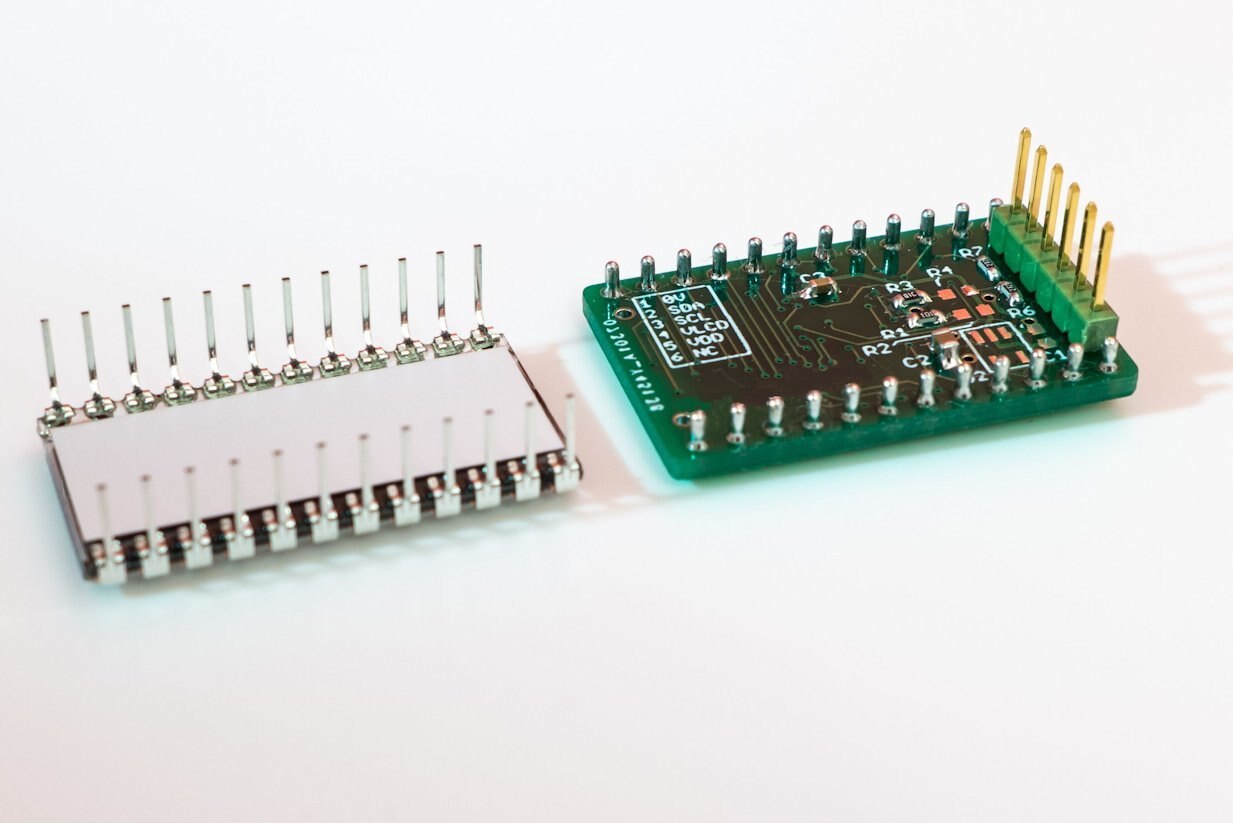
Order the boards from a PCB firm (the files are attached to this post). Once the PCBs arrive, the first step is to solder the PCF85176 chip. It is quite small (0.5mm spaced pins) but hand-soldering is still possible. A hot plate and solder paste would be another option. I just used a normal soldering iron (2mm tip) and no-clean flux (cleaned up afterwards) and thin solder.


The hardest part is perfect alignment. The way I do it is to tape the IC onto the PCB first. Then, inspect the pins using a magnifying lens. If it looks incorrect, peel the tape from one end but keep the IC attached to the tape. Move the tape and re-stick it onto the PCB. It becomes quite easy to align the IC and secure it in this manner, just moving the tape from one side at a time.


Next, apply a small amount of no-clean flux and start soldering. Any bridges will fall away if you re-heat with the iron, but if the bridge is persistent then use de-soldering braid. The soldering iron needs a bit of solder applied to the tip in order to get the solder-wicking effect when using the braid.


Optionally use pin sockets (or SIL sockets) so that the LCD does not need to be soldered. It is highly recommended that sockets are used to protect the LCD and also because it would be difficult to unsolder the LCD if there was a problem with the PCF85176 that needed examining.

After all the parts have been soldered clean the board using an IPA solution and then examine each pin on the PCF85176 under a lens (push each pin gently with the side of a scalpel blade) to verify all is well.
image


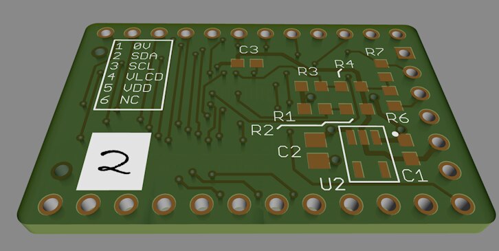
If the display only needs to operate from 3.3V then you don’t need to solder the linear regulator IC and its associated capacitors. If multiple displays on the same I2C bus are needed then the addresses are programmed using two 10k resistors that can be soldered in different positions (see the source code for a table which indicates this).
image


The attached files are slightly improved to the boards that I used, in that there is a white space for labelling them if multiple displays are needed for a single project.


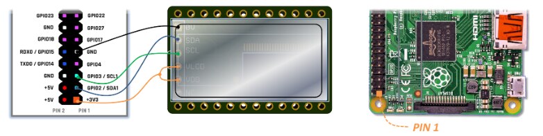
After checks for any short circuits, the LCD can now be connected up to the Pi.
image


Software

As a quick test some C code was written for the ‘Pi. It was tested using a Pi 2 but should work on others, there is nothing special to the code.

To enable I2C on the ‘Pi, add the following line to /boot/config.txt (you need to be root user to do this):

dtparam i2c_arm=on


Reboot the Pi and then type (as root user):

modprobe i2c_dev


To make it persistent across reboots you can add the following (as root user) to the /etc/modules file:

i2c-dev


Grab the code from github. To compile the code type the following:

gcc -c i2cfunc.c -o i2cfunc.o
ar rcs libi2cfunc.a i2cfunc.o
gcc lcd3-test.c -L. -li2cfunc -o lcd3-test


To run it, type:

./lcd-test


Currently the code can display decimal points, digits 0-9 and space.

To use it, call the print_line() function. Here are some examples:

print_line(" 0.0");
print_line("1.23");
print_line("   "); // clear the screen
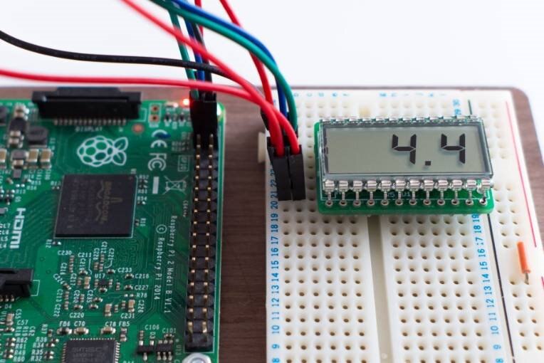
 

image


The I2C interface is a standard, and it would be very easy to port the code across to any microcontroller/Arduino/etc.


Summary

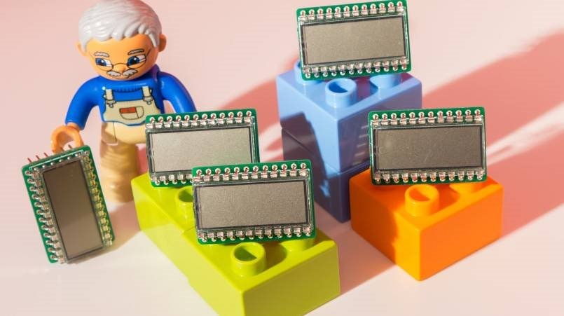
NXP’s I2C LCD chip continues to be useful after two decades. The cost, size and low power consumption are attractive for some use-cases. Although this project uses surface mount components they are cheap enough that it could be a useful board to practice with. The very low power consumption means that a couple of AA batteries should last for five years or more with the display always on.
 

image


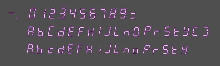
Advanced Use: Extending the Character Set

Many characters are possible with 7-segment displays.
image

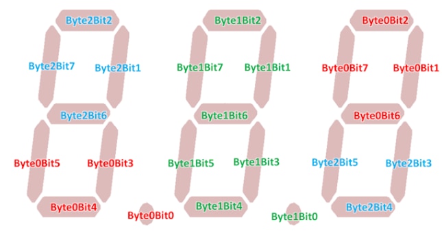
Three bytes represent which segments are to be activated. Refer to the diagram to see the bit mappings.
image


To extend the character set to display hyphens or alphabet characters, the following array needs to be extended:


const char bit_table[]=
{
  0x38, 0x00, 0x86,    0x00, 0xbe, 0x00,    0x86, 0x00, 0x38,    /* 0 */
  0x08, 0x00, 0x02,    0x00, 0x0a, 0x00,    0x02, 0x00, 0x08,    /* 1 */
  0x30, 0x00, 0x46,    0x00, 0x76, 0x00,    0x46, 0x00, 0x30,    /* 2 */
  0x18, 0x00, 0x46,    0x00, 0x5e, 0x00,    0x46, 0x00, 0x18,    /* 3 */
  0x08, 0x00, 0xc2,    0x00, 0xca, 0x00,    0xc2, 0x00, 0x08,    /* 4 */
  0x18, 0x00, 0xc4,    0x00, 0xdc, 0x00,    0xc4, 0x00, 0x18,    /* 5 */
  0x38, 0x00, 0xc4,    0x00, 0xfc, 0x00,    0xc4, 0x00, 0x38,    /* 6 */
  0x08, 0x00, 0x06,    0x00, 0x0e, 0x00,    0x06, 0x00, 0x08,    /* 7 */
  0x38, 0x00, 0xc6,    0x00, 0xfe, 0x00,    0xc6, 0x00, 0x38,    /* 8 */
  0x18, 0x00, 0xc6,    0x00, 0xde, 0x00,    0xc6, 0x00, 0x18     /* 9 */
};


The first group of three bytes indicates the segments that need to be turned on for the digit in the leftmost position, the second group of three refer to the center digit and the last three refer to the rightmost digit. If ASCII sequence is not followed then modify the char_prog function accordingly.


To enable the extra characters, the print_line function case statement checks can be extended.

Attachments:
export-lcd3.zip
export-lcd3-rev2.zip
export-lcd3-rev2-with-board-outline.zip
  • low_power
  • eagle
  • eagle-cad
  • lcd
  • rpiintermediate
  • lcd display
  • eagle_cad
  • raspberry_pi
  • display
  • nxp
  • raspberry_pi_projects
  • feature_tutorial
  • Share
  • History
  • More
  • Cancel
  • Sign in to reply

Top Comments

  • Jan Cumps
    Jan Cumps over 9 years ago in reply to shabaz +5
    Works fully now I'll create a follow up blog with the ported code.... edit: done - Building a Low Power Compact LCD Display - Port to Hercules Safety Microcontroller
  • DAB
    DAB over 10 years ago +4
    Great post Shabaz. You provide good information on how to use different LCD screens and interface them to a MCU. DAB
  • Jan Cumps
    Jan Cumps over 9 years ago +4
    I'm going to play along. I'll first try to talk to it with a Bus Pirate v4. Then as a low power reception indicator for a Sub-1GHz range test...
  • shabaz
    shabaz over 10 years ago in reply to kooth

    Hi kooth and modalpdx ,

    Thank you for spending time reading the blog and the nice comments! It is very much appreciated.

    • Cancel
    • Vote Up +1 Vote Down
    • Sign in to reply
    • More
    • Cancel
  • kooth
    kooth over 10 years ago

    Very well done!  And it is great that you read the comments and corrected things that were a little off!  You do great work, my friend!

    • Cancel
    • Vote Up +1 Vote Down
    • Sign in to reply
    • More
    • Cancel
  • modalpdx
    modalpdx over 10 years ago in reply to shabaz

    Yay, more excuses to buy more components! This sounds like a simple and fun one to try out. Thanks for writing it up!

    • Cancel
    • Vote Up +1 Vote Down
    • Sign in to reply
    • More
    • Cancel
  • shabaz
    shabaz over 10 years ago in reply to e14 Contributor

    I've edited the board, labelled it revision 2.

    Now the mapping should be correct, and doesn't need manipulation in the software.


    I won't update the main post, since it isn't tested for real yet, but if you do get a chance to try it (or if I build some more, which I probably will at some stage) then I'll update the main article.

    The changes are low risk, since the rev 1 has been proven to work; this rev 2 has been DRC checked.

    The CAM files are attached to the main post (since I cannot add them to the comment here) filename export-lcd3-rev2.zip

    Just to summarise, the original file export-lcd3.zip contains the older mapping that is corrected in software, and the new file export-lcd3-rev2.zip has a corrected mapping which will simplify the code. The renders below show the export-lcd3-rev2.zip output. (I took the opportunity to tidy the silkscreen slightly too, and remove the resistor R5 which was unused). The inner wide rectangle on the top side show where a cutout/window can be made if it is fitted inside an enclosure. The white filled square on the underside is for labelling with a pen, if several of the boards are to be connected to the same I2C bus.

    image

    • Cancel
    • Vote Up +1 Vote Down
    • Sign in to reply
    • More
    • Cancel
  • shabaz
    shabaz over 10 years ago in reply to e14 Contributor

    Hi Kalle,


    Ahh,, thank you for identifying the root cause! I see it now. You're right, I've just checked, and I'd created the CAD part incorrectly, which leads to the inconsistency, i.e. the datasheet was correct.

    It was a silly mistake, I'd numbered the pins 13..24 back-to-front : ( Probably did a mirror command of 1..12 which I would normally do, but then this time forgot to manually edit the numbering : (

    For SMD I have my own automated scripts so it wouldn't have made this error, but through-hole I still do manually.

    • Cancel
    • Vote Up +1 Vote Down
    • Sign in to reply
    • More
    • Cancel
  • e14 Contributor
    e14 Contributor over 10 years ago in reply to shabaz

    Hi Shabaz,


    It's not the LCD datasheet, but the PCB isn't routed according to the schematic. Take e.g. NXP pin 26 near the corner. It should go to LCD pin 16 so that it would light up LCD segment G3. In reality, it goes to LCD pin 21, which indeed lights up LCD segment B1, as discovered in the end of the article.


    So it's the classic case of fixing a hardware bug in software image.

    • Cancel
    • Vote Up +2 Vote Down
    • Sign in to reply
    • More
    • Cancel
  • shabaz
    shabaz over 10 years ago in reply to e14 Contributor

    Hi Kalle,


    Excellent point.. I agree as you say that it should, but either there is a mistake in the LCD datasheet, or we have both misinterpreted it in the same way.

    (In general many LCD datasheets are very sparse, some are incorrect, something gets lost in translation!).


    As a result, it was found that despite it theoretically mapping to separate bytes with the schematic under 'Building It', in reality it didn't, and so the mapping in the code was used.

    A later schematic/PCB revision could correct the mapping to reflect reality, so that the mapping in the code can be simplified. However it is only three digits to map, and can be done with little code

    and at high speed, so I felt it was not worth the effort to re-spin the design, since the software mapping had a low overhead.


    In summary the schematic shown, CAD files and graphic mapping diagram and code mappings are all sync'd, and will work together.

    • Cancel
    • Vote Up +1 Vote Down
    • Sign in to reply
    • More
    • Cancel
  • e14 Contributor
    e14 Contributor over 10 years ago

    The schematic under the heading 'Building It' doesn't seem to match the actual segment mapping. That should make the characters appear in separate bytes instead of the real mapping shown in the end of the article.

    • Cancel
    • Vote Up 0 Vote Down
    • Sign in to reply
    • More
    • Cancel
  • shabaz
    shabaz over 10 years ago in reply to ntewinkel

    Hi Nico,


    Thanks!

    In the past I've done circuit design in an R&D lab, and indirectly now, it still helps for work.

    Also used self-designed stuff for demo'ing/exercising products.

    Sometimes fun stuff, like a while back we used an Atmel chip and LED displays for a competition,

    see who can make the product fall over with the least amount of ball throws!

    With software it is a habit for me, for example last week I needed to use some virtualization technologies

    for work, but I did it on an SBC (a Pi) first, to prove things out and start getting my documentation sorted.

    By using the actual platform and a different but 'near-enough' platform I sometimes end up learning a lot

    more about the process and learn subtleties that may otherwise be missed.

    • Cancel
    • Vote Up +2 Vote Down
    • Sign in to reply
    • More
    • Cancel
  • ntewinkel
    ntewinkel over 10 years ago in reply to ntewinkel

    ps, do you do this kind of thing (designing electronics) for a living? Looks totally professional image

    • Cancel
    • Vote Up +1 Vote Down
    • Sign in to reply
    • More
    • Cancel
<>
element14 Community

element14 is the first online community specifically for engineers. Connect with your peers and get expert answers to your questions.

  • Members
  • Learn
  • Technologies
  • Challenges & Projects
  • Products
  • Store
  • About Us
  • Feedback & Support
  • FAQs
  • Terms of Use
  • Privacy Policy
  • Legal and Copyright Notices
  • Sitemap
  • Cookies

An Avnet Company © 2026 Premier Farnell Limited. All Rights Reserved.

Premier Farnell Ltd, registered in England and Wales (no 00876412), registered office: Farnell House, Forge Lane, Leeds LS12 2NE.

Follow element14

  • X
  • Facebook
  • linkedin
  • YouTube