

(Note: For a follow-up project which uses a larger screen, click here:Building a 3.5 Digit Low Power LCD Module )

Introduction
Sometimes a really simple, low power display is needed. A lot of information can be shown on even a 7-segment display!
This LCD board project could be useful for such purposes. The three 7-segment digits (and two decimal places total, between the digits) can show percentages, hexadecimal values, voltages and current readings. Plenty of characters can be represented too.
Up to four of these displays can be connected to a single I2C bus so (for example) a power supply project could use one display for voltage and another for current, for two channels. To save costs for smaller projects a single display could be used to show more than one item of information using a button press or periodic cycling of data on the display.

The reflective LCD that is used has no backlight but has very good contrast and in tests had excellent visibility even in dim light. The power consumption is extremely low and this makes it ideal for portable projects which might need to run for years on batteries without charging. The entire bill-of-materials is less than £5GBP (or lower if multiple displays are purchased).
The schematic and plot (gerber) files and source code is attached to this post. I had 20 PCBs made for less than the cost of a pizza.

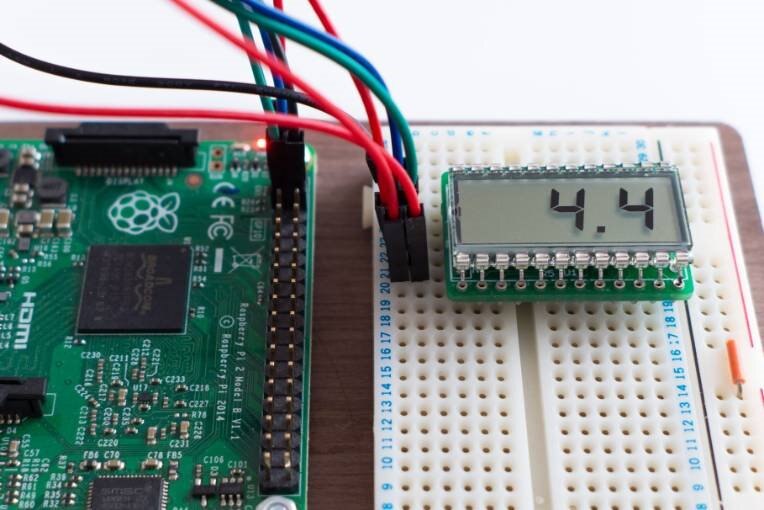
As a quick test I tried it using a Raspberry Pi just counting up from 0.0 to 99.9. With very little effort it would be possible to use it to display Pi stats – for example temperature, or the IP address (one byte at a time) upon start-up. It is easy to get any script to write to the display from the command line.
Features Summary
- 3.3V or 5V capable
- Ultra-low current consumption (24uA at 3.3V)
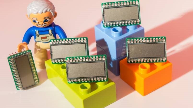
- Extremely compact; 32x21mm
- Just a 4 wire connection; I2C Interface, 0V and VDD (3.3V or 5V)
- Individually addressable segments for alphanumeric and other symbol use
- Quick to assemble; less than a dozen parts
- Low cost; about £5GBP in quantities of 1
Parts List
| Ref | Code | Mnfr Part # | Description | Qty | GBP Each |
| LCD1 | 18389301838930 | LCD-S301C31TRLCD-S301C31TR | LCD 3-digit | 1 | 1.85 |
| U1 | 24004602400460 | PCF85176T | LCD Driver | 1 | 1.18 |
| C3 | 17591221759122 | MC0603B104K500CT | 100N 0603 x7r | 1 | 0.01 |
| R1, R3 | 20733492073349 | MCMR06X1002FTLMCMR06X1002FTL | 10K Res 0603 | 2 | 0.01 |
| R2, R4, R5 | D.N.F. | 0 | 0.00 | ||
| R6, R7 | 93319729331972 | MC0063W060352K7MC0063W060352K7 | 2.7k Res 0603 | 2 | 0.01 |
| J1 | 15934151593415 | 2211S-06G2211S-06G | SIL header 6-way | 1 | 0.26 |
| Optional | 177848177848 | D01-99012 01 | PCB pin sockets 12-way | 2 | 1.18 |
| Optional | 22998562299856 | 0552-2-15-01-21-27-10-00552-2-15-01-21-27-10-0 | PCB pin sockets (alternative) | 24 | 0.07 |
Additional components for 5V operation
| Ref | Code | Mnfr Part # | Description | Qty | GBP Each |
| U2 | 23143722314372 | TPS70925DBVTTPS70925DBVT | LDO 2.5V Voltage Regulator | 1 | 0.82 |
| C1 | 19073431907343 | C1608X7R1C105K080AC | 1u 0603 X7R | 1 | 0.04 |
| C2 | 17355421735542 | GRM21BR71E225KA73LGRM21BR71E225KA73L | 2.2u 0805 X7R | 1 | 0.24 |
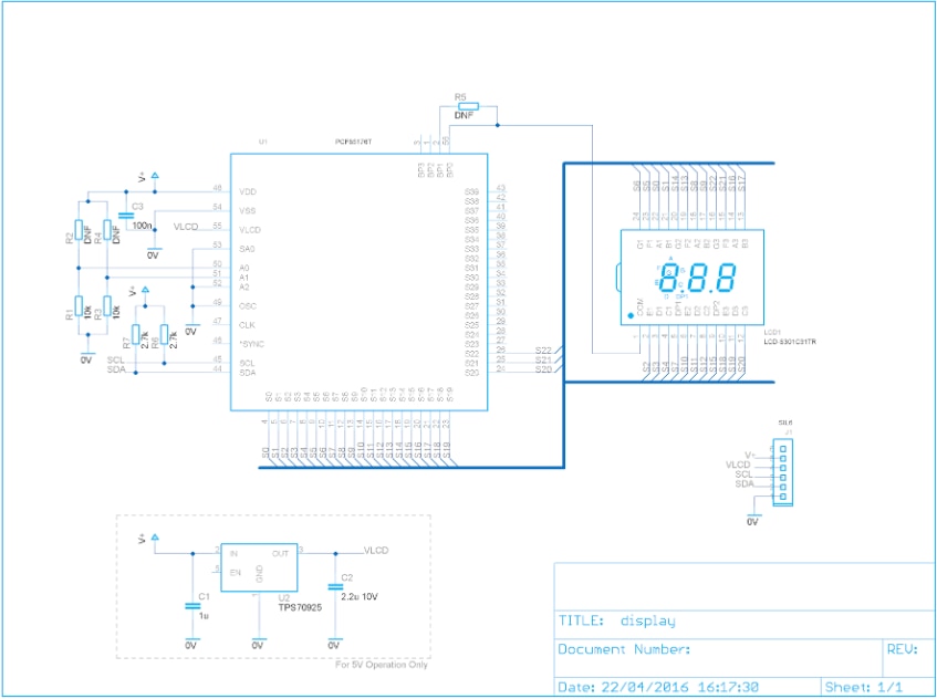
How it Works
There are different types of LCDs, but in general they require an alternating current (AC) signal to turn on segments. Some use a square wave, others require multiple voltage levels in order to achieve high segment density with low pin count through multiplexing.
The particular LCD chosen requires a square wave, and has the benefit of providing high contrast digits. Reflective displays offer high contrast but have the disadvantage that they are opaque from the underside and cannot be lit from behind so require either ambient light to be visible or a side light.
Some microcontrollers feature LCD driving capability but there is a classic integrated circuit from NXP that is useful to offload the task from microcontrollers and allow the use of an I2C bus for interfacing. That IC is the PCF8576 which has been around for more than two decades. NXP have a more recent IC called PCF85176 (it appears to be backwards-compatible) and that is the one used for this project because it has very low power consumption requirements and a higher speed I2C bus capability than its predecessor.
Nothing else is needed apart from a few resistors and capacitors.
The LCD needs a few volts peak voltage in order to function. For 5V operation a linear regulator provides the lower voltage to run the LCD.
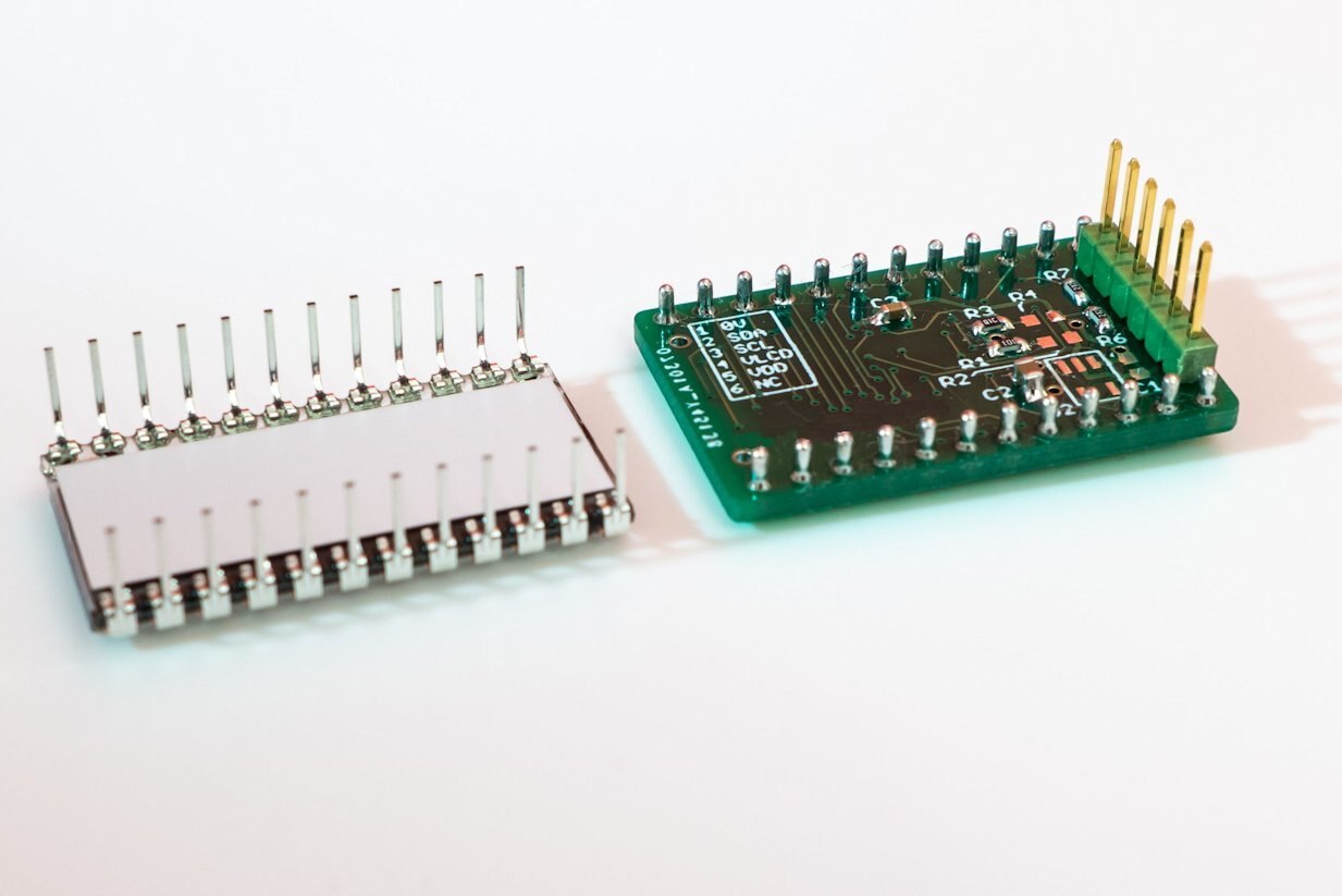
Building It
Order the boards from a PCB firm (the files are attached to this post). Once the PCBs arrive, the first step is to solder the PCF85176 chip. It is quite small (0.5mm spaced pins) but hand-soldering is still possible. A hot plate and solder paste would be another option. I just used a normal soldering iron (2mm tip) and no-clean flux (cleaned up afterwards) and thin solder.
The hardest part is perfect alignment. The way I do it is to tape the IC onto the PCB first. Then, inspect the pins using a magnifying lens. If it looks incorrect, peel the tape from one end but keep the IC attached to the tape. Move the tape and re-stick it onto the PCB. It becomes quite easy to align the IC and secure it in this manner, just moving the tape from one side at a time.
Next, apply a small amount of no-clean flux and start soldering. Any bridges will fall away if you re-heat with the iron, but if the bridge is persistent then use de-soldering braid. The soldering iron needs a bit of solder applied to the tip in order to get the solder-wicking effect when using the braid.
Optionally use pin sockets (or SIL sockets) so that the LCD does not need to be soldered. It is highly recommended that sockets are used to protect the LCD and also because it would be difficult to unsolder the LCD if there was a problem with the PCF85176 that needed examining.
After all the parts have been soldered clean the board using an IPA solution and then examine each pin on the PCF85176 under a lens (push each pin gently with the side of a scalpel blade) to verify all is well.
If the display only needs to operate from 3.3V then you don’t need to solder the linear regulator IC and its associated capacitors. If multiple displays on the same I2C bus are needed then the addresses are programmed using two 10k resistors that can be soldered in different positions (see the source code for a table which indicates this).
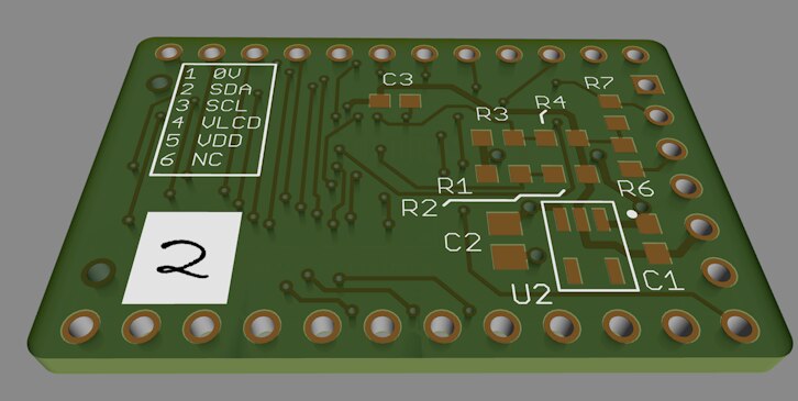
The attached files are slightly improved to the boards that I used, in that there is a white space for labelling them if multiple displays are needed for a single project.
After checks for any short circuits, the LCD can now be connected up to the Pi.
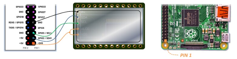
Software
As a quick test some C code was written for the ‘Pi. It was tested using a Pi 2 but should work on others, there is nothing special to the code.
To enable I2C on the ‘Pi, add the following line to /boot/config.txt (you need to be root user to do this):
dtparam i2c_arm=on
Reboot the Pi and then type (as root user):
modprobe i2c_dev
To make it persistent across reboots you can add the following (as root user) to the /etc/modules file:
i2c-dev
Grab the code from github. To compile the code type the following:
gcc -c i2cfunc.c -o i2cfunc.o
ar rcs libi2cfunc.a i2cfunc.o
gcc lcd3-test.c -L. -li2cfunc -o lcd3-test
To run it, type:
./lcd-test
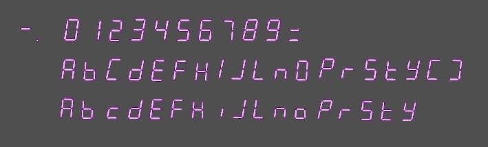
Currently the code can display decimal points, digits 0-9 and space.
To use it, call the print_line() function. Here are some examples:
print_line(" 0.0");
print_line("1.23");
print_line("   "); // clear the screen
The I2C interface is a standard, and it would be very easy to port the code across to any microcontroller/Arduino/etc.
Summary
NXP’s I2C LCD chip continues to be useful after two decades. The cost, size and low power consumption are attractive for some use-cases. Although this project uses surface mount components they are cheap enough that it could be a useful board to practice with. The very low power consumption means that a couple of AA batteries should last for five years or more with the display always on.
Advanced Use: Extending the Character Set
Many characters are possible with 7-segment displays.
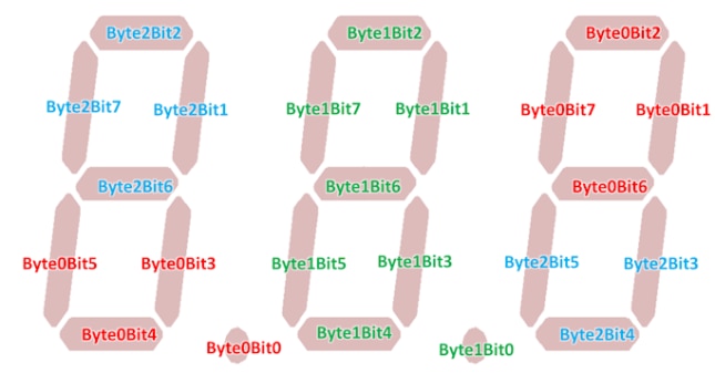
Three bytes represent which segments are to be activated. Refer to the diagram to see the bit mappings.
To extend the character set to display hyphens or alphabet characters, the following array needs to be extended:
const char bit_table[]=
{
  0x38, 0x00, 0x86,    0x00, 0xbe, 0x00,    0x86, 0x00, 0x38,    /* 0 */
  0x08, 0x00, 0x02,    0x00, 0x0a, 0x00,    0x02, 0x00, 0x08,    /* 1 */
  0x30, 0x00, 0x46,    0x00, 0x76, 0x00,    0x46, 0x00, 0x30,    /* 2 */
  0x18, 0x00, 0x46,    0x00, 0x5e, 0x00,    0x46, 0x00, 0x18,    /* 3 */
  0x08, 0x00, 0xc2,    0x00, 0xca, 0x00,    0xc2, 0x00, 0x08,    /* 4 */
  0x18, 0x00, 0xc4,    0x00, 0xdc, 0x00,    0xc4, 0x00, 0x18,    /* 5 */
  0x38, 0x00, 0xc4,    0x00, 0xfc, 0x00,    0xc4, 0x00, 0x38,    /* 6 */
  0x08, 0x00, 0x06,    0x00, 0x0e, 0x00,    0x06, 0x00, 0x08,    /* 7 */
  0x38, 0x00, 0xc6,    0x00, 0xfe, 0x00,    0xc6, 0x00, 0x38,    /* 8 */
  0x18, 0x00, 0xc6,    0x00, 0xde, 0x00,    0xc6, 0x00, 0x18     /* 9 */
};
The first group of three bytes indicates the segments that need to be turned on for the digit in the leftmost position, the second group of three refer to the center digit and the last three refer to the rightmost digit. If ASCII sequence is not followed then modify the char_prog function accordingly.
To enable the extra characters, the print_line function case statement checks can be extended.
Top Comments