

| BUY NOW | Technical Documents | Video | Features | Kit Contents |
| Overview
Raspberry Pi is adding a new hardware module, Compute Module Development KitCompute Module Development Kit, to its line-up specifically aimed at businesses and industrial users. The Kit contains a Compute Module, a Compute IO Board, and a Display Adapter & a Camera Adapter.
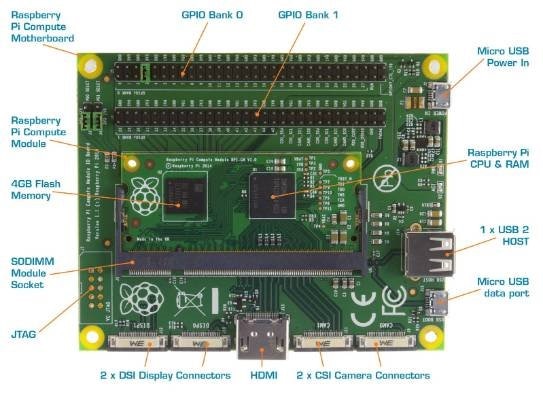
The compute module contains the guts of a Raspberry Pi (the BCM2835 processor and 512Mbyte of RAM) as well as a 4Gbyte eMMC Flash device (which is the equivalent of the SD card in the Pi). This is all integrated on to a small 67.6x30mm board which fits into a standard DDR2 SODIMM connector (the same type of connector as used for laptop memory*). The Flash memory is connected directly to the processor on the board, but the remaining processor interfaces are available to the user via the connector pins. You get the full flexibility of the BCM2835 SoC, which means that many more GPIOs and interfaces are available as compared to the Raspberry Pi, and designing the module into a custom system should be relatively straightforward as we’ve put all the tricky bits onto the module itself.
The Compute Module IO Board is a simple, open-source breakout board that you can plug a Compute Module into. It provides the necessary power to the module, and gives you the ability to program the module’s Flash memory, access the processor interfaces in a slightly more friendly fashion (pin headers and flexi connectors, much like the Pi) and provides the necessary HDMI and USB connectors so that you have an entire system that can boot Raspbian (or the OS of your choice). This board provides both a starting template for those who want to design with the Compute Module, and a quick way to start experimenting with the hardware and building and testing a system before going to the expense of fabricating a custom board.
The Compute Module IO Board has a 22-way 0.5mm FFC for two camera ports, with CAM0 being a 2-lane interface and CAM1 being the full 4-lane interface. To attach a standard Raspberry Pi Camera to the Compute module IO Board a small camera adaptor board is used to adapt the 22W FFC to the Pi 15W FFC. The Compute Module also has 2 MIPI serial display interfaces (DSI); a small camera adaptor board included in the kit is used to adapt the 22W FFC to the Pi 15W FFC. | |||

Technical Documents
Learning Center
Design Elements
Video
| Video 1 | Video 2 |
|---|---|
Kit Features
Compute Module
- SODIMM sized (6.5cm by 3cm) Raspberry Pi board that contains the BCM2835 chip with 512MB RAM along with an on board 4GB eMMC Flash memory for booting the operating system.
- The 200 pin edge connector will provide the design engineer with access to all of the BCM2835 functionality.
- Certified to FCC class B as it is expected to be integrated into domestic applications
Compute Module IO Board
- Multiple GPIO interfaces
- 1 x micro USB connector type B
- 1 x USB connector type A
- 2 x CSI ports for camera boards
- 2 x DSI ports for display boards
- Full size HDMI port
- Micro USB power connector
- Certified to FCC Class B and contains a socket to connect the Compute Module
Display & Camera Adapters
- 1 x 22 way to 15 way CSI camera adapter
- 1 x 22 way to 15 way DSI display adapter
Kit Contents
- 1x Quick start guide
- 1x Raspberry Pi Compute Module (CM)
- 1x Raspberry Pi Compute Module IO Board (CMIO)
- 1x Raspberry Pi CMIO to Raspberry Pi Camera adaptor board
- 1x Raspberry Pi CMIO to Raspberry Pi Display adaptor board
- 2x 22 way 0.5mm FFC cables (for use with camera and display adaptor boards)
- 1x 5V power supply
- 1x USB A to micro B data cable
- 4x Female to female jumper wires
