


This blog post focusing on the MDO 3 Series Spectrum Analyser is part of the 3 Series MDO Mixed Domain Oscilloscope - Review.
Review version 1.0 - 28 Januari 2020, initial release
Table of contents
RF spectrum analyser
The MDO34 Mixed Domain Oscilloscope has a built-in spectrum analyser with a dedicated RF input for significantly higher dynamic range than an oscilloscope using a regular input and an FFT function, resulting in:
- ~15 dB better dynamic range than scope FFT
- RF support to 3 GHz in a 100 MHz – 1 GHz scope
- Doesn’t use one of the scope’s four analog inputs (3 series MDO provides standard N- connector input for spectrum analyzer)
As this is a real spectrum analyser, I can compare it to another real spectrum analyser. In this case I will compare it to the performance of the 3GHz Spectrum Analyzer - R&S FPC1000 - Review.
Measuring harmonics of HAM radio transmitters.
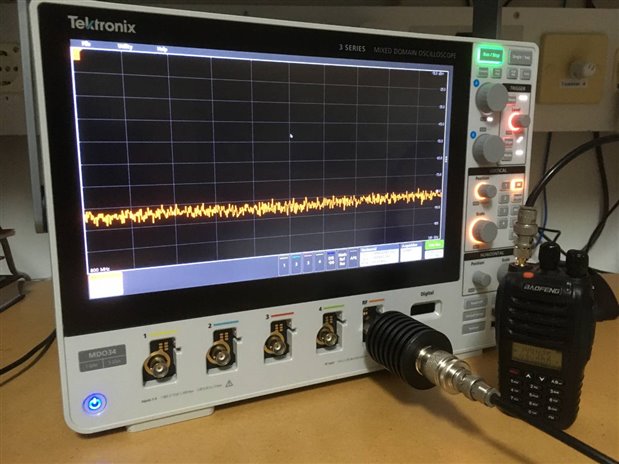
Similar as with the FPC1000 I tested MDO34's spectrum analyser to measure unwanted signals from my HAM radio transmitters. I have two handhelds around, the first one is a Teleport 9 from AEG. This is a solid and very robust portable transceiver for the 2 m band. Visitors of the main Dutch airport (Schiphol in Amsterdam) may remember these brick-size blue handies being used by all airport service personel. The AEG Teleport 9 was part of a trunking network used by all services at the airport and has now been replaced by a more modern (and smaller) alternative. The old units ended up in the HAM radio community and have been converted by Rob Spijker, PE1RJY, into amateur transceivers covering the entire 2 m band. The second one is a cheap Chinese dual band handheld Baofeng UV-5B.

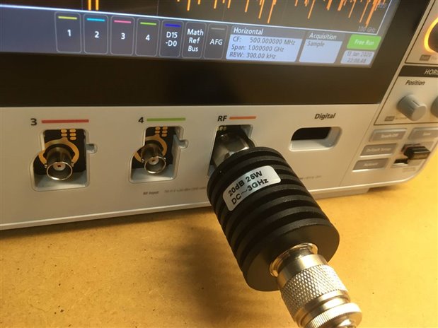
The power output of the radio's is 0.5 and 1.7 W respectively. These power levels are far too much for the spectrum analysers maximum input of +20 dBm (100mW).
Therefore I'm using a 20dB (100x) attenuator, in order to attenuate the radio power to 5 and 17 mW, which is in range with the specifications.
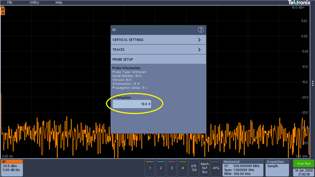
In the RF menu probe setup you can specify the amount of attenuation used. Unfortunately this value is not in dB as expected, but just a multiplication (division) factor. Even more confusing is that this value is the attenuation in voltage, rather than power. So the factor for this 20dB attenuator is not 100 as I expected, but 10. For a future software update I propose Tektronix to switch to dB for this setting.
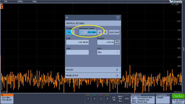
Another issue that can be improved is the maximum reference level, which is the maximum power level, as shown by the baseline indicator at the top of the frequency graticule.
This level can not be set above 20 dBm, which is fine for no attenuation, but with attenuation I would propose that this value can be increased till 20 dBm plus the attenuation (in dB).
For my measurements the signal is larger than 20 dBm as you can see later.
Let's have a look at the radios. First the Baofeng:
Compared to the FPC1000 there is no predefined harmonics measurement mode, but automatic markers pop up at signals which are larger than a certain threshold:
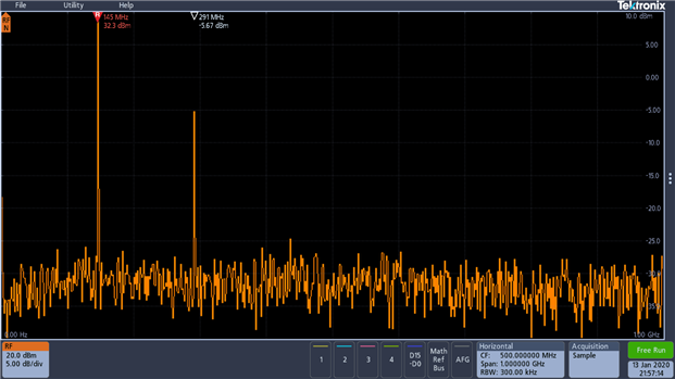
From this picture you can see the expected signal, 32.3 dBm (1.7W) and a very strong 2nd harmonic at 290 MHz. To be honest, this radio is not compliant with the regulations. In the Netherlands regulations state that unwanted signals must be -60 dBc (60 dB below carrier signal), which is not the case here. The resolution bandwidth (RBW) used is 300kHz. Most spectrum analysers (e.g. the FPC1000) also have the option to change the video bandwidth (VBW) which is related to the displayed trace quality. Video filtering is a time-domain low-pass filter, mathematically equivalent to the mean or average. The main effect of the VBW filter is to smooth the trace and decrease noise. Unfortunately the MDO34 does not have this option. Although the frequency domain window supports four spectrum traces. You may turn each of these traces on or off independently. You can display all or some of them simultaneously.
- Normal trace: Each acquisition is discarded as new data is acquired.
- Max hold trace: The maximum data values are accumulated over multiple acquisitions of the Normal trace.
- Min hold trace: The minimum data values are accumulated over multiple acquisitions of the Normal trace.
- Average trace: Data from the Normal trace is averaged over multiple acquisitions. This is true power averaging, which occurs before the log conversion. Each power of 2 averaging reduces the displayed noise by 3 dB.
Since I was curious whether there is also a third harmonic, I tried the average trace option, using an average of 64 traces:
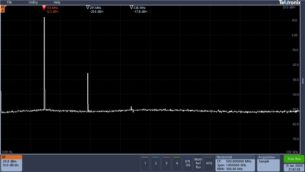
As you can see there indeed is a third harmonic, which is just -60dBc.
Now let's have look at the Teleport 9:
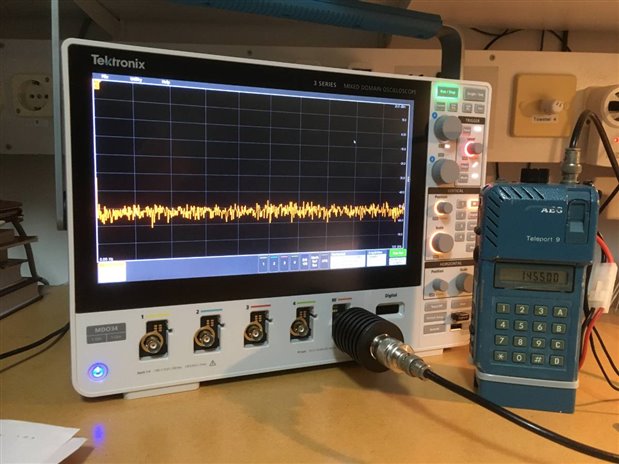
As can be seen in the screenshot below this radio is compliant with the regulations, there is no noticeable harmonic signal.
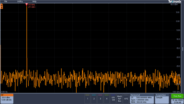
What also can be noted is that the signal at 145 MHz is larger than the scale. I would expect a warning that the signal is clipped.
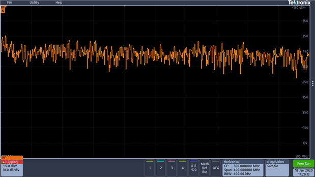
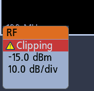
While in the signal below there is such a clipping warning, although I don't see any problems, which is confusing.
The documentation states:
WARNING. Clipping is caused by excessive or dangerous voltages at the probe tip and/or a vertical scale setting that is not adequate to display the entire vertical range of the waveform. Excessive voltage at the probe tip can injure the operator and cause damage to the probe and/or instrument.
This instrument shows a warning triangle symbol and the word Clipping in a Channel badge when a vertical clipping condition exists.
During this test I encountered a number of advantages of the FPC1000 above the MDO34.
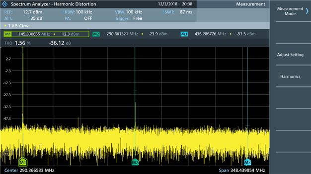
- The FPC has a dedicated harmonics measurement function, which immediately gives information on the 2nd and 3th harmonic.
- In addition, the R&S FPC also calculates the total harmonic distortion (THD). The THD is the root mean square of all harmonics in relation to the power of the fundamental frequency.
- The FPC1000 detects overloads on the input signal. In that case the upper right corner shows 'IF Ovl', with an additional beep signal. The MDO34 clipping warning in the channel badge should be similar to this, but how this functions is confusing.

- Attenuation/power level issues mentioned above.
- Also despite the big screen of the MDO34, the FPC1000 shows a much cleaner signal on the screen, including relevant settings and measured values. I have the impression that more and finer points are used to draw the traces. Below is a screenshot of the FPC1000, for comparison.
Measuring filter characteristics.
A spectrum analyser is a great tool to measure filter characteristics, or antenna performance, but the spectrum analyser needs to be equipped with a tracking generator to do so. By linking the sweep of the spectrum analyzer to the tracking generator, the output of the tracking generator is on the same frequency as the spectrum analyzer, and the two units track the same frequency. More information can be found e.g.: https://www.electronics-notes.com/articles/test-methods/spectrum-analyzer/spectrum-analyser-tracking-generator.php.
Unfortunately the MDO34 similar to the FPC1000 doesn't have one, so end of the story.
Luckily not, another solution to show behaviour of a certain filter is by using a wideband noise source. This noise source generates wideband noise, ideally at a steady signal level. This can be used as a cheap substitude of a tracking generator.
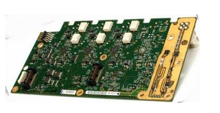
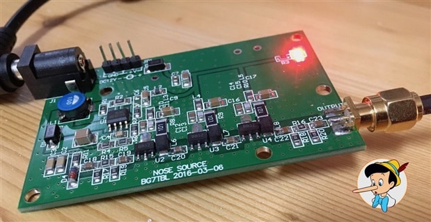
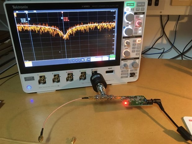
BG7TBL designed a rather cheap wide-band noise source, called "NOSE SOURCE" as mentioned on the PCB. I bought one on eBay (version 2016-03-06) and tested it in combination with the MDO34, as I previously did with the FPC1000.
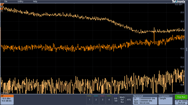
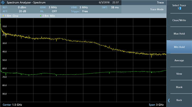
Lets have a look at the signals. Below is a picture of the 'Max hold' and 'Min hold' traces (light orange) with noise source on and off, and the normal trace (orange) with the noise source off. This gives an impression on the difference between the noise level of the MDO34 and the output of the noise generator. As can be seen the signal is reasonable flat until 1.5 GHz, but also above that frequency usable. I have to admit that I'v put the device on 10V in stead of 12. On 12V the PCB gets terribly hot presumably since the Ub voltage of the MMICs is 7V compared to the max rating of 5.5V in the specs. By putting the device on 10V the Ub voltage is in accordance with the specs. The total power output on 10V is slightly less than on 12V but still very usefull.
Compared to the R&S, to my opinion the FPC1000 shows a much more clear signal than the MDO34.
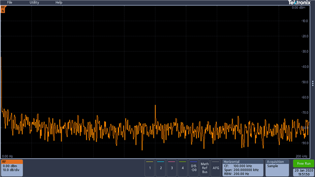
When looking at the very beginning of the spectrum, 0-200 kHz, there are some peaks, probably from the switching power supply on the PCB.
Largest level is 0 dBm, which is below the max input range, but to be sure I used the 20dB attenuator. That might be a reason the the signal differs form what I previously measured with the FPC1000 (3GHz Spectrum Analyzer - R&S FPC1000 - Review ).
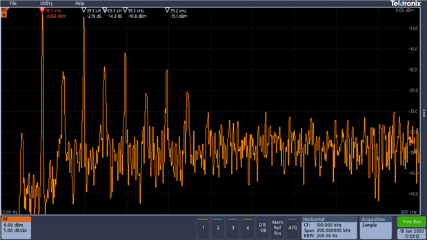
Below a picture of the MDO34 noise floor in this region.
Now lets have a look at some filters:
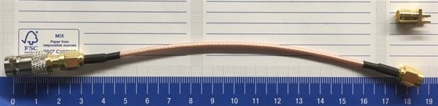
The tested filter is a very simple yet powerful notch filter for instance to suppress harmonics from a transmitter. It consists of a single open ended piece of ordinary coaxial cable at a quarter of the wavelength you like to quash. These filters will generate sharp, deep notches which can be placed on the harmonics of your transmitter. To test its performance I'v put a BNC T adapter on the output of the noise source and connected a small piece of coax.
The frequency of the notch can be calculated by:

Where f is he frequency in MHz, Vp the velocity factor (Coax Velocity Factor | Coaxial Cable Velocity Factor | Radio-Electronics.com ) for the coaxial cable (here 0.66) and L the length of the coax in meters.
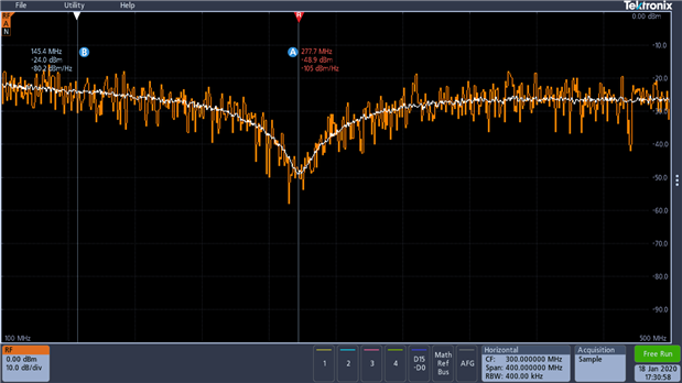
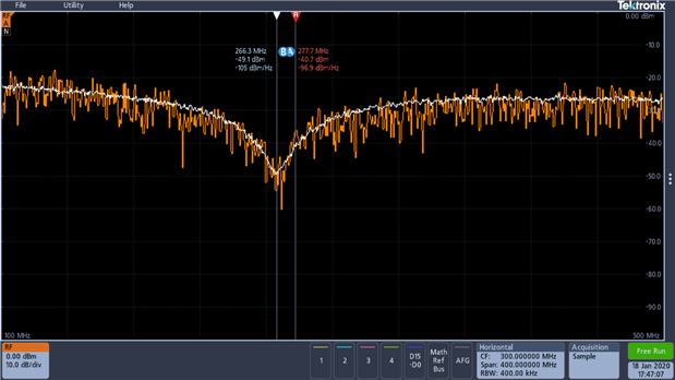
For the coax stub below the frequency should be about: 0.66*300/(4*0.19) = 260 MHz.
I used the normal trace, and an average over 64 trace. The result is close to the calculated value, and almost similar to what I found with the FPC1000.
I used the markers to point to the frequencies of interest. The MDO34 provides two markers, which are different from the automatic peak markers, mentioned above.
The FPC1000 has four markers of just one type, used either automatically or manual. To me this is more intuitive than how this is implemented on the MDO34.
By cutting the cable a little bit, it should be possible to put the notch at the second harmonic of the Baofeng radio mentioned above. This harmonic is then attenuated by 25 dB, which makes the output of the radio compliant with the regulations.
When making the cable a little bit longer by connecting a SMA socket.
f = 0.66*300/(4*0.20) = 248 MHz.

And yes the frequency is indeed 12 MHz lower than the previous one.
For more information, please have a look at the website on Coaxial Stub Filters from G4SWX.
For now this concludes the experiments for the spectrum analyser part of the 3 Series MDO Mixed Domain Oscilloscope - Review.
In order to stick to the 60 days review period I was not able to do more tests, but I promise I will add more tests later.
For general remarks and a conclusion you can go back to the main review page.
Top Comments