element14 Community
element14 Community
    Register Log In
  • Site
  • Search
  • Log In Register
  • Community Hub
    Community Hub
    • What's New on element14
    • Feedback and Support
    • Benefits of Membership
    • Personal Blogs
    • Members Area
    • Achievement Levels
  • Learn
    Learn
    • Ask an Expert
    • eBooks
    • element14 presents
    • Learning Center
    • Tech Spotlight
    • STEM Academy
    • Webinars, Training and Events
    • Learning Groups
  • Technologies
    Technologies
    • 3D Printing
    • FPGA
    • Industrial Automation
    • Internet of Things
    • Power & Energy
    • Sensors
    • Technology Groups
  • Challenges & Projects
    Challenges & Projects
    • Design Challenges
    • element14 presents Projects
    • Project14
    • Arduino Projects
    • Raspberry Pi Projects
    • Project Groups
  • Products
    Products
    • Arduino
    • Avnet Boards Community
    • Dev Tools
    • Manufacturers
    • Multicomp Pro
    • Product Groups
    • Raspberry Pi
    • RoadTests & Reviews
  • Store
    Store
    • Visit Your Store
    • Choose another store...
      • Europe
      •  Austria (German)
      •  Belgium (Dutch, French)
      •  Bulgaria (Bulgarian)
      •  Czech Republic (Czech)
      •  Denmark (Danish)
      •  Estonia (Estonian)
      •  Finland (Finnish)
      •  France (French)
      •  Germany (German)
      •  Hungary (Hungarian)
      •  Ireland
      •  Israel
      •  Italy (Italian)
      •  Latvia (Latvian)
      •  
      •  Lithuania (Lithuanian)
      •  Netherlands (Dutch)
      •  Norway (Norwegian)
      •  Poland (Polish)
      •  Portugal (Portuguese)
      •  Romania (Romanian)
      •  Russia (Russian)
      •  Slovakia (Slovak)
      •  Slovenia (Slovenian)
      •  Spain (Spanish)
      •  Sweden (Swedish)
      •  Switzerland(German, French)
      •  Turkey (Turkish)
      •  United Kingdom
      • Asia Pacific
      •  Australia
      •  China
      •  Hong Kong
      •  India
      •  Korea (Korean)
      •  Malaysia
      •  New Zealand
      •  Philippines
      •  Singapore
      •  Taiwan
      •  Thailand (Thai)
      • Americas
      •  Brazil (Portuguese)
      •  Canada
      •  Mexico (Spanish)
      •  United States
      Can't find the country/region you're looking for? Visit our export site or find a local distributor.
  • Translate
  • Profile
  • Settings
RoadTests & Reviews
  • Products
  • More
RoadTests & Reviews
Blog 4.3 LCD Display Cape for Beaglebone Board - Review
  • Blog
  • RoadTest Forum
  • Documents
  • RoadTests
  • Reviews
  • Polls
  • Files
  • Members
  • Mentions
  • Sub-Groups
  • Tags
  • More
  • Cancel
  • New
Join RoadTests & Reviews to participate - click to join for free!
  • Share
  • More
  • Cancel
  • Author Author: andyash01
  • Date Created: 20 May 2021 6:27 PM Date Created
  • Views 2025 views
  • Likes 13 likes
  • Comments 3 comments
Related
Recommended
  • cape
  • touch
  • bb-cape-disp-ct43
  • TFT LCD
  • beagle bone
  • hacking
  • linux

4.3 LCD Display Cape for Beaglebone Board - Review

andyash01
andyash01
20 May 2021

Eh! What?

  • I recently purchased the BB-CAPE-DISP-CT43BB-CAPE-DISP-CT43 for my Seeed Studio Beaglebone Green.
  • I'm pretty familiar with bare metal, but I want to do a modern GUI for an instrument I am building.
  • Linux seems to offer a way forward with good GUI capabilities
  • The Beaglebone with the TI Sitara is quite transferrable to a new PCB design with other components.
  • The BB-CAPE-DISP-CT43BB-CAPE-DISP-CT43 looked like a good way to put an LCD display on the Beaglebone for a bit of a software lash-up.


Summary

  • It works. It's cheap. I like it.
  • There were some problems.
  • I've written about the problems here because I wish someone else had told me.


I'm not kidding

image

Look! there it is, it works. image


The Problems

  • When I was buying it, I was never too sure if it would work with the Beaglebone Green.

The Farnell page says "for Beaglebone Black". Beaglebone black has an HDMI interface and framer. I don't know how that works but I do know that the Beaglebone Green does not have an HDMI framer.

I wasn't sure if the LCD would need it, but I guessed it would connect to the LCD port which is physically a part of the TI Sitara microprocessor.

Luckily I was right. This cape works happily with Beaglebone Green.


  • I wasn't too sure how to make the LCD interface work in the Linux environment.

The Farnell page refers to a pretty flimsy data sheet.

Frankly it's not very encouraging, it doesn't even show the display with any software running on it.

They offer a readme saying that some aspects of the board aren't really supported yet.

It looks a bit shonky form a software perspective.


Actually it's all fine. You don't need any software from Farnell at all.

All you need to do is load the most recent IOT SD card image from the Beaglebone site.


At the time of writing the latest image is "AM3358 Debian 10.3 2020-04-06 4GB SD IoT".

You can download it here


Graphics on the LCD is inherently supported. The machine will boot to a text mode console on the graphical LCD display.

If you want a Linux desktop just install one. You will get a login dialog box and then a graphical desktop.


You can find instructions for the LXDE install here

Use the instructions for LXDE on Debian Wheezy the other instructions might work too - I didn't try those


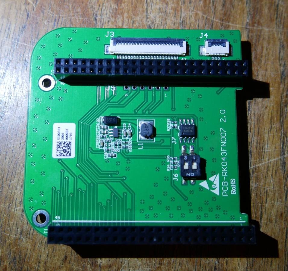
  • There are no schematics for the board.

There is barely anything on the board, so you might think you don't need one.

Actually you don't really know what's happening there, and if it doesn't work you're left guessing.

It's pretty lamentable that there are no schematics available, it encroaches on Raspberry Pi territory. image

It's hardly an NDA thing, it's just a boost regulator and an EEPROM, after all.


  • I was unlucky. Out of the box mine had an electrical fault.

Not knowing the previous three things I lost a lot of time to research. I was trying to figure out why the software was wrong.

Actually, it wasn't until I inspected the LCD electrical signals I realised that the 10MHz LCD clock was not right.

On my oscilloscope I could see the signal was stuck high and "all spikey like".

Using a multi-meter I was able to identify that the the clock signal was shorted to the 3.3V rail.

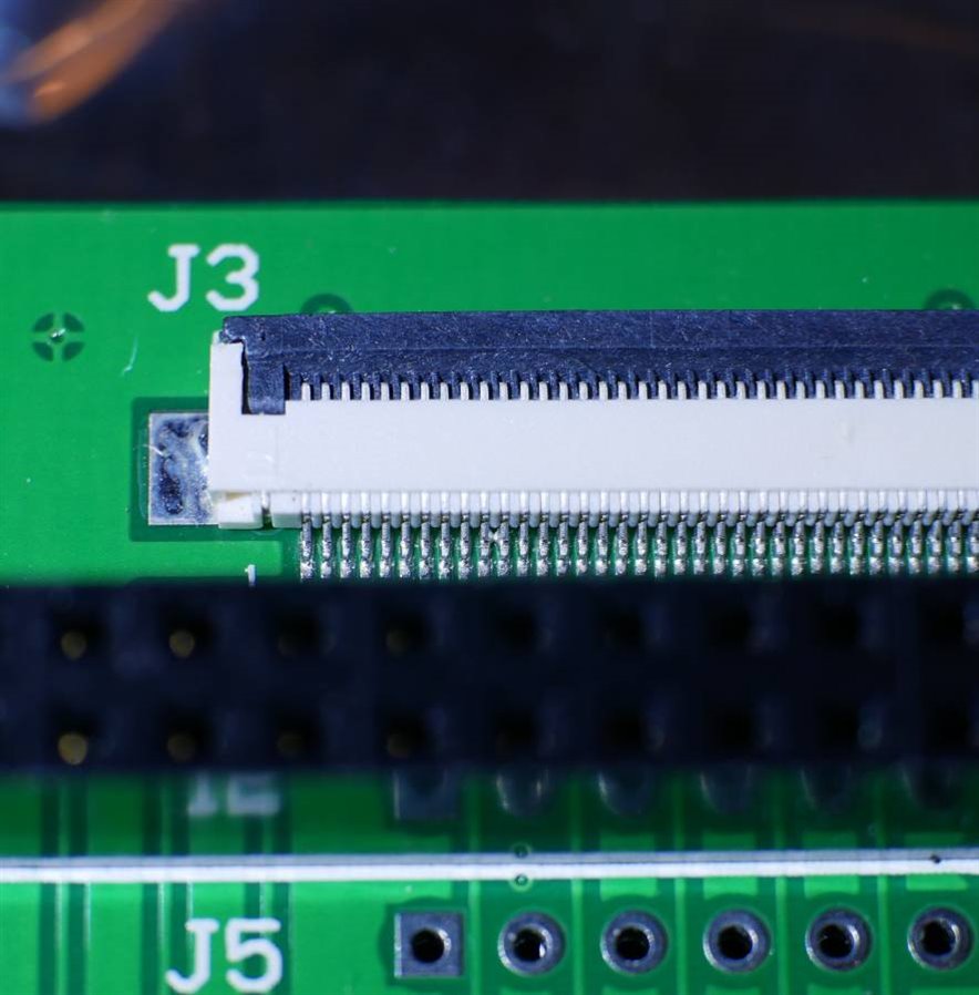
Careful visual inspection revealed a short on the LCD flex connector. Picture below;


image


The basic design of the board is not well thought out. I can see already that the failure rate on these boards is going to be high and that they cannot easily be tested.

Testing would have been possible but not at the price the board is sold at.

I suggest that it is quite likely that other people will see failures on these boards too.


If you get a board with a fault like this Farnell are very good about returns. I decided to fix mine.

In the picture below you can see the problem;


image


The 0.1" pitch header is very close to the LCD flex connector. You can't easily get in with a soldering iron to clear the short.

I flooded the area with liquid flux. I have a Weller TCP iron with a screwdriver tip "Weller ETB". It's a pretty chunky iron, and you have to be careful not to melt the header.

I folded the end over on some solder wick and hooked it over the top of the connector. I applied the iron vertically to the board and pushed outwards against the wick and the connector.

It took a lot of attempts to catch and soak up the short. Be patient and use lots of flux. You can clear the short without melting the connector, even with a chunky iron.


Happy hacking.

image


  • Sign in to reply

Top Comments

  • ralphjy
    ralphjy over 4 years ago +3
    It's a shame that they don't do a simple functional test or at least a visual inspection of the units. But I guess we've all experienced defective electronic products due to skipping test to reduce cost…
  • 14rhb
    14rhb over 4 years ago +2
    Great work saving that board - a return would likely have been scrapped. Your setup would look great in a Peli case IMO
  • kmikemoo
    kmikemoo over 4 years ago +1
    andyash01 AWESOME write-up! Problem -> Solution. I really appreciate you addressing your concerns based on the sparse information and what you figured out. I often hit those walls and decide not to proceed…
  • kmikemoo
    kmikemoo over 4 years ago

    andyash01  AWESOME write-up!  imageimage  Problem -> Solution.  I really appreciate you addressing your concerns based on the sparse information and what you figured out.  I often hit those walls and decide not to proceed.  Great job.

    • Cancel
    • Vote Up +1 Vote Down
    • Sign in to reply
    • More
    • Cancel
  • ralphjy
    ralphjy over 4 years ago

    It's a shame that they don't do a simple functional test or at least a visual inspection of the units.  But I guess we've all experienced defective electronic products due to skipping test to reduce cost.  I'm glad that you managed to successfully remove the solder short without too much difficulty.  That was a tough spot to work on.

    • Cancel
    • Vote Up +3 Vote Down
    • Sign in to reply
    • More
    • Cancel
  • 14rhb
    14rhb over 4 years ago

    Great work saving that board - a return would likely have been scrapped. Your setup would look great in a Peli case IMO image

    • Cancel
    • Vote Up +2 Vote Down
    • Sign in to reply
    • More
    • Cancel
element14 Community

element14 is the first online community specifically for engineers. Connect with your peers and get expert answers to your questions.

  • Members
  • Learn
  • Technologies
  • Challenges & Projects
  • Products
  • Store
  • About Us
  • Feedback & Support
  • FAQs
  • Terms of Use
  • Privacy Policy
  • Legal and Copyright Notices
  • Sitemap
  • Cookies

An Avnet Company © 2025 Premier Farnell Limited. All Rights Reserved.

Premier Farnell Ltd, registered in England and Wales (no 00876412), registered office: Farnell House, Forge Lane, Leeds LS12 2NE.

ICP 备案号 10220084.

Follow element14

  • X
  • Facebook
  • linkedin
  • YouTube