


Road Test Introduction
It was an honor to be selected for the road test of the Advantech USB-5830 16 channel digital I/O (each) module. I have been working with crypto-mining rigs and had felt that there is a need to architecting a “smart” high-density facility power management system. It was fortuitous that the USB 5830 actually appears to be an easy path to integrate a potentially very high-density AC power switching system. Since each module could support 16 digital channel out, that is potentially 16 circuits that can be controlled by one module. With the ability to daisy-chain modules (they are individually addressable when done so), I can easily scale up to 32 circuits and so on and so forth at multiples of 16, combined with available Linux driver, all can be controllable by an inexpensive Linux SBC.
What I received
On or around the prescribed date, a package arrived at my front porch from Advantech. It was nicely packaged, complete with security tape typically used to indicate that it was sealed from the factory. It appears to have been opened, likely by the fine folks at e14, more on that in the next section.
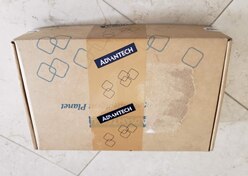
(Picture of Package Received)
Unpacking
Everything needed to get started are in the box, including a thoughtfully placed tiny thumb size screwdriver and a USB stick presumably with driver and manuals as there was no paper manual in the box. Just a pamphlet in multiple languages to encourage you to register and receive two extra months of warranty. In the box included the USB module itself as well as an “industrial” version of USB cable for the “up-chain” connector on the USB-5830 and a USB-B on the other end. Both ends included a thumb screw to fasten the connector more tightly to where they are connected to. Nice quick connect blocks were included which is (I believe) the reason for the inclusion of the tiny thumb size Philips screwdriver. Although a flat driver might make better sense since the actuation mechanism on the quick connect wiring blocks would probably work better, nevertheless, it was functional and as the old saying goes, never look a gift horse in the mouth. Most importantly, there was a green Microcenter branded 8GB USB sticks. I suspect this may or more likely may not be part of the normal package and the reason mine was opened. It included driver software preloaded. So that the kind e14 staff are able to provide necessary software and documentation without me having to scour the internet in a mad dash scramble.
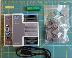
(Content of Package Received)
Project Concept
In addition to the above-mentioned items in the package. The project called for additional devices as first a quick proof of concept. It calls for a digital relay circuit board that can enable or disable a higher voltage circuit I have used on previous Arduino and Raspberry-Pi projects. I chose the 8-channel unit for this prototype since it matches the two banks of 8 digital outs perfectly. The standard “rainbow” ribbon cable can also be easily and inexpensively obtained via the interweb. The female side connects perfectly to the relay board. The male side, unfortunately, was a little large to fit into the holes on the quick connect blocks. Undaunted, I used a utility knife and whittled the connectors individually down on each corner so that they would fit into the quick connect blocks and make the proper contact. Note for the future, order jumper cables with round connectors to likely avoid the same issue.
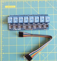
(Picture of Relay Board and ribbon cable)
Also, to make quick work of the prototype, I chose a power strip with the individual switch to each of the socket so I can just hack and rewire the switches to the relay. I could only find a 6-switch version (plus 1 master switch). It would leave an extra digital channel unused but for my price range and delivery schedule, it was the best option available at the moment. If the product was to ever be commercialized, it would include a custom socket and layout that makes the most sense. For the prototype/proof of concept, this is more than adequate and the path of least resistance.
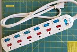
(Picture of Switched Power Strip)
Driver Installation
The first step to stand up any device is to install its driver in a known system. Although the plan is to use a Beagle Bone to drive multiple USB-5830 to scale up a high-density power switch, I decided to test out the module first on a Windows system since all of the documentation makes much more references to Windows. Using my trusty Dell Inspiron 7000 series laptop, I unzipped the included USB-5830 driver and ran the install executable. I chose to install the DAQNavi_USB5800 installable since it most closely resembles the device I am trying to install.

(DAQNavi_USB5800_4.0.6.0.zip Install Screen)
A few status updates later, the USB-5830 appeared in the Device Manager without incident. However, aside from being able to see the device in the Device Manager, very little, if anything could be done with the module so a little more scouring of the internet and reading a few readme files lead to finding that there is more software needed for something called the Device Navigator.
SDK Installation
This step could have benefitted from a quick start to summarize the needed software installation steps. My original interpretation of the SDK was simply that it included the call libraries and sample code to use the API. Last thing I would have expected that it also included all of the utility software as well. After searching and not finding the standalone Navigator installable executable, I decided to give the SDK install a whirl. What could go wrong, right? It is a step I will eventually need anyway if I was going to develop custom code. The install was rather substantial (as opposed to the 5830 installable). Note the install screen. Can you spot the difference?
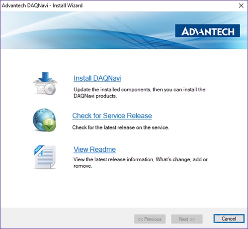
(DAQNavi_SDK_4.0.0.0.zip Install Screen)
No, that was a trick question. There are no differences. The first time I tried, I thought I ran the wrong executable, clicked Cancel, went back to the unzipped executable and started again. It may have been a convenience to re-use existing asset, but the developer should have at least added the difference (SDK vs 5800 driver) so that it would be more user-friendly. Not that I should complain, it is quite trivial especially now that I put it in words. What’s a little confusion and click and clicking again between friends, right? At any rate, by the time it was done, voila! All sort of shortcut was added to my Windows Start Menu and sample code from every known development platform in existence has been installed. Remember Delphi? It’s there. As well as just about every language you can think of, including C, C++, C# and various sundry of others. Most interesting to me are the LabVIEW drivers and MATLAB drivers. I enjoy working on rapid application development platform such as those to really speed up initial prototyping processes and their inclusion is much appreciated. And sure enough the Advantech’s Device Navigator was also installed and shortcut included. With that, we are in business.
Testing the Module
The Advantech Device Navigator is a GUI to explore installed Advantech devices and it works pretty much like any hierarchical expand and collapse tree structures just like you would find in File Explorer or Finder, except it is for Advantech Devices. The USB-5830 showed up under Installed Devices and underneath it, if you expand its branch/root, it included a Test Page that I was able to use to interact with each of the installed devices. The Test Page included multiple tabs including Input, Output and quite a bit of other options. Since my main interest was the Digital Out, I was quickly able to tick a few boxes and generated a pattern of On and Offs on the 16 Digital Output Channels. This is a great way to quickly diagnose and troubleshoot issues with external modules. So far the USB-5830 is working great.


Wiring up the Relay Board
This part is relatively trivial other than having to trim the existing connectors to fit in the quick connect block. However, I could not measure any meaningful voltage on the Digital Output channels regardless of the indicated state by the module. Not a problem, many I/O modules require an external power source and since there are two (dual redundant) PSU input blocks, it made sense that I simply have to provide a usable power source.
Wiring up a Power Supply
This is where the project had to sadly come to a screeching halt. My simple idea of using the most conveniently available power source (a 18650 battery clip) was grabbed and quickly wired up to the power source. However, after unable to measure any voltages, more digging into the manual revealed that the proper input voltage should be ~10VDC to 30VDC. As I don’t have a readily available power supply source the rest of the project will have to be put on hold until I am able to source a power supply. I have always felt that I need a decent power supply source for my home workshop. Now I have more reason to get one. This is not a knock to the module. It operated as expected. It is more of a setup issue for my integration. I have complete confidence that once set up properly, everything will just work when I wire up the module to the relay board to switch the power strip. Once that occurred, I will be that much closer in realizing an easily integrated, high-density power management system.
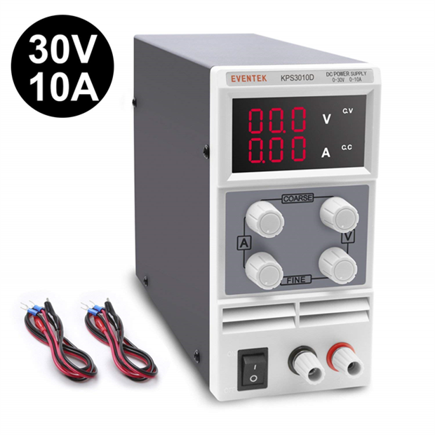
(Thwarted by not just spend the money and buy this)
Conclusion
The Advantech USB-5830 is a great out of the box solution to instantly add 16 digital output (and input) to any computing devices that includes a USB port. It is compact and rugged. I will continue to work with it to see to the completion of my project and provide an update when available. All in all, I believe a little quick start documentation would go a long way in most experienced hand. While I had to make a few educated guesses, it essentially just worked. Not much you can ask for in an industrial I/O module intend to be used for professional applications. Great product. I recommend wholeheartedly.
Top Comments