


Previous blog posts of my MSOX3034TMSOX3034T Road Test:
Keysight InfiniiVision MSOX3034T RoadTest | Unboxing & First Impressions
Hello Everybody!
It has been about 4 weeks since I received the Keysight InfiniiVision MSOX3034TMSOX3034T mixed signal oscilloscope.
Since then I had the opportunity to start exploring the scope. I read the User's Guide and took a look on the built-in Training Signal and Demo-s of the scope.
But let's take a look on the specifications first!
1. Specifications
Oscilloscopes usually have a lot of numeric values in their specifications:
- bandwidth of hundreds of MHz-s
- sample rate of billions of samples / second
- update rate of hundreds of thousands of updates / second.
- megapoints of sample memory
But what each of these values mean? For a somewhat beginner user like me it may not be clear at the first look.
An oscilloscope allows visualizing electrical signals in two dimensions. The horizontal (X) axis represents time, while the vertical (Y) shows voltage.
To do this, the scope passes signal through several components before it is displayed on the screen. The components include the analog front-end, sampler, ADC and the sample memory.

The Keysight InfiniiVision MSOX3034TMSOX3034T is a mixed signal oscilloscope with 4 analog and 16 digital channels.
The analog bandwidth of our model (3034T) is 350 MHz. This means the analog front-end of the oscilloscope can handle signals up to 350 MHz bandwidth with a signal drop of maximum 3dB (70.7%).
The bandwidth of the MSOX3034TMSOX3034T is optionally upgradable to 500MHz (DSOXT3B3T54) or to 1 GHz (DSOXT3B3T104U, return to service center required). Other models from the 3000T series are available from 100 MHz to 1 GHz bandwidth.
The maximum sample rate of the scope is 5 GSa/s. This means the analog signal is sampled 5 billion times each second. When the channels 1 & 2, or 3 & 4 are used together the maximum sample rate is 2.5GSa/s.
Each analog sample is being converted to digital by the analog-to-digital converter (ADC) to a digital value and stored in the sample memory. The ADC resolution of the scope is 8 bits, which means each analog voltage sample is represented as an 8 bit integer.
The sample rate and ADC resolution are the two main factors determining how much detail the displayed signal contains.
The waveform update rate of the scope is 1,000,000 wfms/s, which is one of the highest within the competition. Each oscilloscope has the some dead-time between acquisitions.

The lower this dead-time is, the more waveforms the oscilloscope can capture in a given amount of time. Having higher update rate means we have higher chance to capture infrequent glitches in our signals
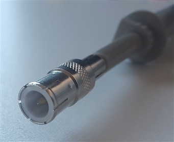
Along the scope the other important thing to consider are the probes. The MSOX3034TMSOX3034T comes with four N2843A probes.

The bandwidth of the probes is 500 MHz, which means it can handle signals of up to 500 MHz without attenuating them with more than 3dB.
The attenuation ratio of the probes is 10:1, while the input impedance is 10 MOhm.
The probes come with Probe ID technology, so the scope can automatically detect their model and set attenuation ratio accordingly.
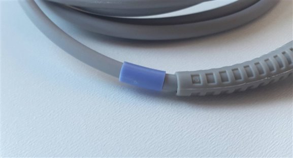
In terms of accessories we get the followings:
- Retractable Hook
- Ground Leads

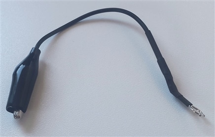
- Spare Tips

- Insulating Caps


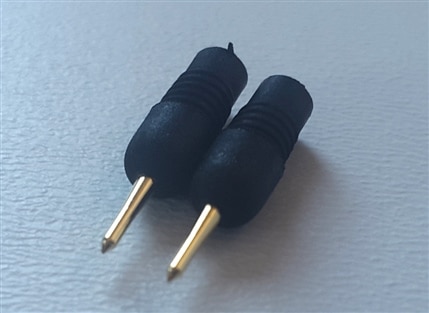


- Ground Springs


- BNC Adapter


- Colored Channel Identification Tags


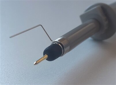


As the accessories came in some pretty flimsy nylon bags, so I decided to store them in a little plastic box instead:
---->

2. Controls and Basic Functionality
Oscilloscopes, tend to be capable of doing more than just displaying electrical signals in two dimensions. They often have additional features and a lot of input / output connectors and controls on their front panel, and some on their back panel.
The MSO-X 3034T, for example, has the following signal inputs and outputs:
- 4 x Analog Input channels
- 16 x Digital Input channels
- 1 x Arbitrary Waveform Generator Output
- 2 x Demo Signal Output terminals + 1 x Ground terminal

On the controls side we have a ton of knobs and buttons, divided in different sections. The MSO-X 3034T also has a touch screen, which makes many operation much easier to perform.
Maybe the most important section, IMHO, on the oscilloscope's interface is the one containing the Default Setup and Auto Scale Button. The Default Setup button lets us go back to the default settings of the scope when we mess things up. The Auto Scale helps to find the best horizontal and vertical scale settings based on the connected input signals.
The Horizontal Controls section is common for all 4 channels, and allows us to control X axis (time) settings, including the time / division and delay (offset) settings. The time / division knob (big) allows to zoom in and out on the X / Time axis. The delay (offset) knob (small) adds a positive or negative delay to the signal, compared to the trigger event.
The Vertical Controls section contains the controls for each individual channel. The buttons 1-4 can be used to enable / disable each of the channels. The vertical scale knob (big) controls the volts / division setting for each channel, and allows us to zoom the signal vertically. The vertical position knob (small) allows moving the signal up / down on the screen.
The Trigger sections allows changing triggering mode and thresholds and the acquisition and coupling modes we want to use. The MSOX-3034T supports a bunch of triggering modes including edge, pulse width, rise/fall time or even video, USB, or NFC signals. The acquisition mode can be auto or normal, for the coupling mode we can choose between DC and AC, and there are other useful feature like Noise Reject or HF reject. The Zone button can be used to enable zone triggering, which is an easy was to set up triggering conditions by drawing boxed directly on the signal displayed on the touch screen.
The rest of the controls include:
- Run/Stop (or Pause) and Single
- Run / Stop - can be used to pause acquisition, and display the last acquired waveform on the screen
- Single - similar to the Run / Stop, but captures and hold the waveform of the next trigger
- Measure & Cursors - a group on controls that allows adding cursors and all kind of automatic measurements to the screen
- FFT, Digital and Math - can be used to enable Fast Fourier Transform (FFT), the digital channels and as well as math functions on the input signal
- Tools & Settings - can be used to access the settings and different build-in tools of the scope
- Contextual Buttons - these can be used to control the setting displayed on the screen above them
Now, as we covered the a basic functions of the oscilloscope, we can use it to inspect some signals.
It's pretty simple. Hook up some probes, turn on channels and hit Auto Scale.
3. In-built Training Signal and Demos
As I not that experienced with oscilloscopes, I decided to start experimenting with the in-built Training Signals and Demos of the scope.
3.1. Training Signals
The scope comes with the following Training Signals.
Sine wave
- 5 MHz sine wave @ ~2.5 Vpp
- can be used to explore the basic functionality of the scope

Sine wave with noise
- 1 kHz sine wave @ ~2.4 Vpp, with random noise of ~0.5Vpp
- can be used to experiment with the Noise Reject, HF Reject, Trigger Holdoff and Waveform Averaging


Two Phase Shifted Sine waves
- two 1 kHz sine waves @ 2.4 Vpp with a configurable phase shift between them
- can be used to show off features like delta-time, phase shift measurements, and XY time mode


Sine wave with glitch
- 30 Hz sine wave @ ~2.7 Vpp with a narrow glitch near each positive peak
- can be used to experiment with the Peak Detect acquisition mode


Amplitude Modulated Sine Wave
- 26 kHz sine wave @ ~ 5 Vpp on Demo 1, amplitude modulated signal, ~2 Vpp, 13 MHz carrier on Demo 2
- can be used to play with features like deep memory, high res display, and trigger on AM


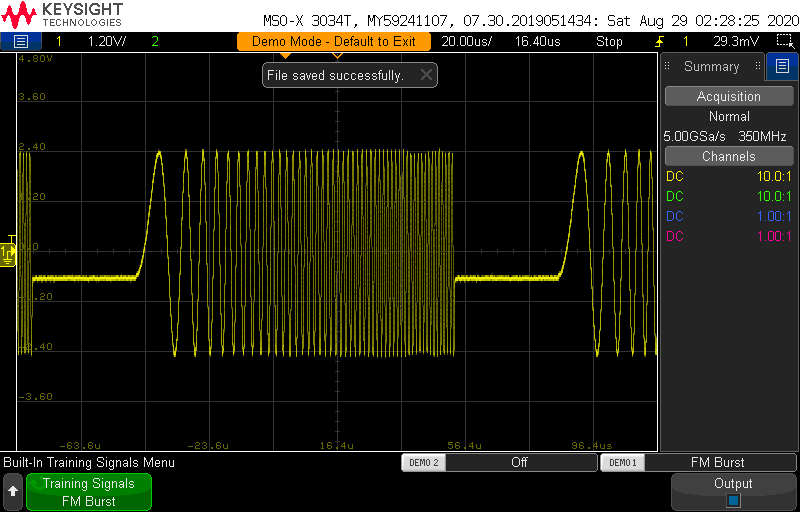
Frequency Modulated (FM) Burst
- Frequency Modulated (FM) Burst from ~100 kHz to ~1 MHz, ~5.0 Vpp, ~600 mV offset
- can be used to show Nth Edge Burst triggering and Measurement Trend Visualization

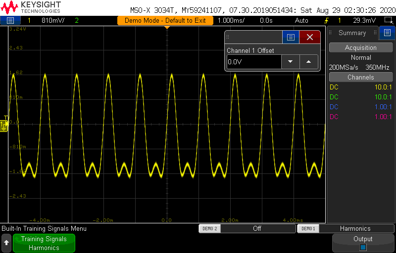
Sine wave with harmonics
- 1 kHz sine wave @ ~3.5 Vpp with 2 kHz sine wave coupled in
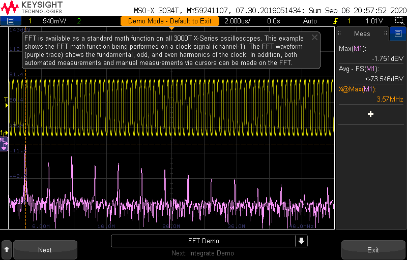
- can be used to demonstrate the FFT capabilities of the scope, and as well as zoom features
Noise coupling
- 1 kHz square wave @ ~1 Vpp, with a ~90 kHz sine wave ~180 mVpp riding on top
- can be used to demonstrate the FFT capabilities of the scope to find signal coupling

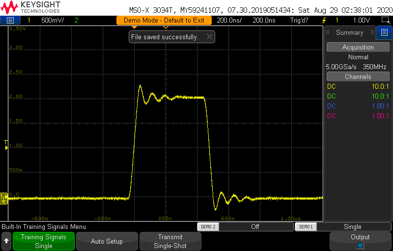
Single shot
- ~500ns wide pulse with ringing @ ~3 Vpp, 1.5 V offset
- can be used to show single-shot acquisition using either Normal triggering or Single acquisition mode
Clock with glitch
- 3.6 MHz clock @ ~2 Vpp, 1 V offset, with infrequent glitch (each 1,000,000th clock)
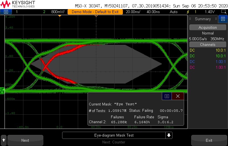
- can be used to demonstrate fast waveform update rate, pulse width triggering and mask testing

Runt
- digital pulse train with positive and negative runt pulses @ ~2.9 Vpp, 1.5 V offset
- can be used to show the benefits of runt triggering, and other features

Setup and Hold
- Demo 1 - 6.25 MHz digital clock @ ~ 3.5 Vpp, 1.75 V offset
- Demo 2 - Data signal @ ~ 3.5 Vpp, 1.75 V offset
- can be used to show of Setup & Hold triggerring

Along the above there a bunch of other training signal, including analog and digital ones. There is even one imitating the KeySight logo:

3.2. Demos
The instrument also comes with a series of Demos:
- Debugging Demos
- Debugging Glitch - Finding the coupling signal that causes a glitch
- Isolating Serial Error - Isolating a serial bus error packet/frame
- Stress Testing - Stress testing FlexRay serial bus using the integrated WaveGen
- Identifying Noise - Identifying a noise source
- Mixed Signal - Debug a mixed signal design using the digital channels
- Gated FFT - Validating the frequency hop of an FSK signal using Gated FFT
- Application Demos
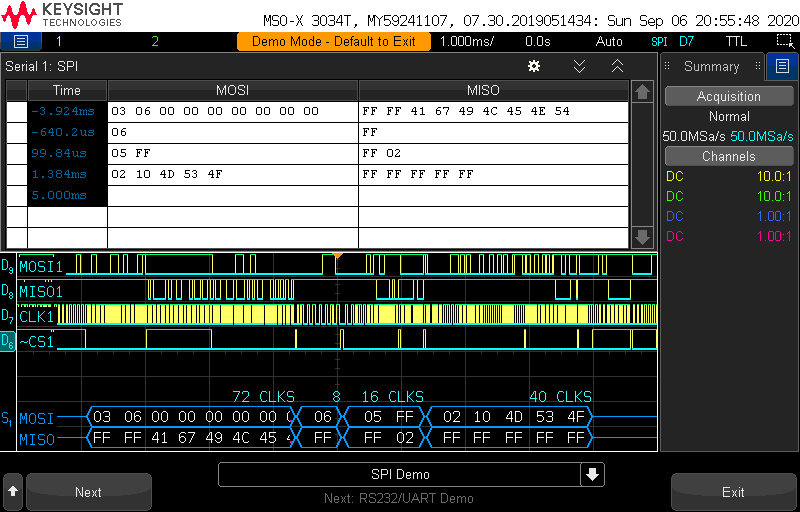
- Serial Buses
- Advanced Triggering
- Advanced Math
- Power Measurements
- Advanced Features
- Auto Demo
- Update Rate
- Zone Trigger
- MSO
- Serial Buses
- Segmented Memory
The Demos were mostly automatic, demonstrating different features of the instrument. The scope does almost all the actions, you just need to press Next time to time.
I would have preferred something more little more interactive. Something like the Training signal section, but with instructions.
Here are some screenshots:
(unfortunately not all the demos allow taking screen captures)


In the next blog post I will try to do some real world experiments.
Stay tuned! 
Resources:
https://www.keysight.com/zz/en/assets/7018-04570/data-sheets/5992-0140.pdf
Top Comments