


In this post we will see some specs about the MSP430FR133 Timers, because a timer will generate the PWM signal that drives the LED
There are two instances of Timer_A that you can use (i.e. Timer_A is not actually a single timer, but two timers – 0 and 1). The naming is a little confusing: Timer0_A3 and Timer1_A3. Why the “3” on the end? That refers to the number of interrupts that each timer can trigger (these are called capture/compare registers, which we’ll get into soon).
The timers can operate off the ACLK (Auxiliary Clock), SMCLK (Sub-main Clock) or an external clock source (TACLK or INCLK). We’ll use the ACLK for our examples, as it still operates in low power modes and runs off the slower VLOCLK (or an external watch crystal).
The Timers, like the MSP430 controllers themselves, are 16-bit timers. It means that we can count up to 16 bits – i.e. 2^16, or 65,535 (in hex, this is 0xFFFF). If we run using a clock frequency of 12kHz (the default for the ACLK), it means the counter can count up to 5.46 seconds (65,535 divided by 12,000). If we were to run the timer off the SMCLK at a 1MHz frequency, we can only count up to 0.05 seconds (or 50 ms) – not that useful.
Each Timer on the MSP430 has 3 CCR’s (Capture/Compare Registers). Remember the naming of the timers – Timer0_A3 and Timer1_A3? The “3” refers to the number of CCR’s per timer.
The capture/compare register allows us to choose whether we want to operate in either capture or compare mode – for now we’ll start by looking at the “compare” functionality.
In Compare mode, the CCR allows us to set the “alarm” that we mentioned earlier, and trigger an interrupt – in other words it compares the current value of the counter to the “alarm” value that has been set. There are 3 CCRs (CCR0, CCR1, CCR2), so we can set 3 different alarms.
For example, say that we want to flash an LED every second. We’re running off the ACLK (Auxiliary Clock) at a frequency of 12kHz. This means that one second passes every 12,000 clock cycles. In order to blink the LED, we write a value of 12,000 into the CCR (as the “alarm”), and write code to handle the interrupt. Each time the counter reaches 12,000 it triggers the interrupt which then flashes the LED. It’s that simple. Well, there’s one extra bit of complexity – Timer Modes. Before we get to Timer Modes, we need to look at the types of timer interrupts.
There are two types of interrupt that the Timers generate.
The first is an interrupt that fires whenever the timer counts to the value in CCR0 (the first Capture/Compare Register). CCR0 gets special treatment as we’ll see a little later. The interrupt flag that is set here is TACCR0-CCIFG
The second type is a general interrupt that fires when:
- the timer counts to the values in either of the other 2 CCRs (i.e. CCR1 and CCR2). The interrupt flag that is set here is TACCR1-CCIFG and TACCR2-CCIFG
The timer overflows past 0xFFFF (65,535) and back to zero. The interrupt flag that is set here is TAIV-TAIFG
We need to do a little bit more work on the second option to work out which of the CCRs triggered the interrupt, but luckily it’s straightforward.
You’re probably comfortable with the concept of interrupt flags. Each of the CCRs has a flag to show whether an interrupt was triggered.
Additionally, there is a general interrupt register that tells us if CCR1 or CCR2 generated an interrupt and a flag to indicate an overflow from 0xFFFF to zero.
The MSP430 Timers can count in 3 different ways, or modes: Continuous mode, Up mode, or Up/Down mode.
Continuous Mode
The timer starts at zero, and counts (once per clock cycle) all the way up to 65,535 (or 0xFFFF). If CCR0 (the “alarm”) is set, the timer triggers an interrupt but keeps on counting up. When it reaches OxFFFF it overflows and returns to zero, just to start counting up again.
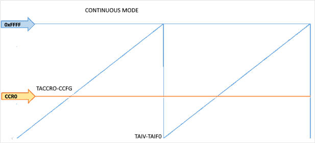
Interrupt Flags:
- If CCR0 is set, then an interrupt is generated and the TACCR0-CCIFG flag is set when the timer reaches CCR0. However the timer will continue to count past CCR0 up to 0xFFFF.
- When the timer overflows, it generates an interrupt and sets the TAIV-TAIFG interrupt flag.
Up Mode
The timer starts at zero and counts up to the value that you specify in CCR0. On the next count it restarts again from zero.
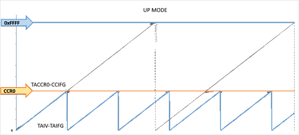
Interrupt Flags:
- When the timer counts to CCR0, it generates an interrupt and sets the TACCR0-CCIFG flag.
- When the timer resets to zero, it generates an interrupt and sets the TAIV-TAIFG flag
Up/Down Mode
The timer starts at zero and counts up to the value that you specify in CCR0. It then counts back down to zero, and starts the cycle again.
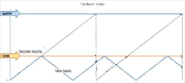
Interrupt Flags:
- When the timer counts to CCR0, it generates an interrupt and sets the TACCR0-CCIFG flag.
- When the timer counts back to zero, it generates an interrupt and sets the TAIV-TAIFG flag
From this you can see that the period between interrupts is double that in Up Mode – as the timer counts all the way back down to zero, rather than resetting at zero.
The Interrupt Service Routine (ISR)
This routine toggles the LED. The way the routine is defined is a little different from “normal” routines. The portion that reads
#pragma vector=TIMER0_A0_VECTOR __interrupt

void Timer_A0(void)
When the interrupt has been processed, the MSP430 re-enters the low power state it was in before the interrupt was triggered. You can prevent this if you want (say, to do other processing in the main() routine) by adding the following line before exiting the ISR:
_bic_SR_register_on_exit(LPM3_bits);
I will use the Timer A1 to generate the PWM that drives the TPS9252. The timer period will be set to 100 us so that I can modulate the PWM frequency in a very flexible way . To configure the Timer A1, a initialization structure is defined
// TimerA1 UpMode Configuration Parameter
Timer_A_initUpModeParam initUpParam_A1_PWM =
{
              TIMER_A_CLOCKSOURCE_SMCLK,              // SMCLK Clock Source
              TIMER_A_CLOCKSOURCE_DIVIDER_1,          // SMCLK/1 = 2MHz
              200,                                    // 100us period
              TIMER_A_TAIE_INTERRUPT_DISABLE,        // Disable Timer interrupt
              TIMER_A_CCIE_CCR0_INTERRUPT_ENABLE ,    // Enable CCR0 interrupt
              TIMER_A_DO_CLEAR,                      // Clear value
              true                                    // Start Timer
};