


The 32.768 kHz crystal oscillator is a popular low-power clock source for many sub-systems in an electronics design. Frequent users of the 32K clock include: Real Time Clock (RTC), processor, RF modems/transceivers, and GPS receivers, just to name a few. Given the large number of potential consumers of a 32K clock in an electronics design, the MAX77714 provides 3 configurable 32K clock outputs on GPIO4 to GPIO6. To enable a 32K clock output in the MAX77714 EVK GUI, one must first enable Alternate Mode on GPIO6 by:

By default, GPIO6 has an open-drain output with no-pullup enabled. There are also no pull-up or pull-down resistors stuffed on the EVK for GPIO4 – GPIO6.

So, we must configure GPIO6 to have a totem-poll output in the GPIO6/7 configuration page as follows:

At this point you will see a clock signal on GPIO6 with levels defined by ‘IN_GPIOB’ which on the EVK is tied to VLOGIC, which is set to 1.8 V in the user’s setup instructions for the EVK. At this point we can measure the output frequency and stability of this clock signal on an oscilloscope, frequency counter, or spectrum analyzer, I elected to use my frequency counter. After connecting up a 10x probe to the GPIO6 test point (which are very nice KEYSTONE 5002 test points) I glanced over at my frequency counter to observe:

Not what I was expecting, 32.91 kHz. That is 4300 PPM off the nominal frequency of 32.768 kHz of the 32k crystal. That is way too high for any of the 32kHz crystals I have ever seen, on top of that the phase noise and stability of the oscillator was several orders of magnitude worse than what I would have expected from a quartz 32k crystal oscillator.
At this point I grabbed my oscilloscope and probed either side of the 32k crystal, no oscillation, not even a DC bias. Upon reviewing the datasheet for the MAX77714, the 32KSOURCE_OTP bitfield configures the PMIC to run with the on die 32k silicon oscillator at reset (not employ the external 32k crystal). This would allow you to omit the 32k crystal if you don’t require accurate time keeping with the RTC, just wish to use the MAX77714 solely as a PMIC.
I proceeded to try and enable the crystal oscillator in the EVK’s GUI, hoping to see the XOSCOK bit to transition high:
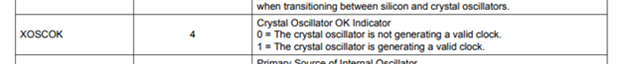
At this point my understanding of the 32k oscillator of the MAX77714 was not as complete as it is now and really was just experimentally bit twiddling in the GUI. The only bit fields presented in the GUI that are writable are:

Fortunately for me, this is the moment, I had an epiphany. I probed the 32K oscillator and saw the crystal oscillator break into oscillation running on the load capacitance of my 10x scope probe. As it turns out, there is no crystal load capacitance bitfield in the 32K_CONFIG (0x31) register, the bit bitfield is located in the 32K_Status (0x30) register and is read-only.


It gets worse, the GUI doesn’t address the PMIC bitfield correctly. Compare the datasheet register definitions to the EVK’s GUI definitions:

The GUI doesn't report the SIOCOK and XOSCOK bitfields, in order to read them one must execute raw I2C reads and writes in the CMOD Advanced UI window. Here, I am reading the 32K_STATUS register with 10x scope probes connected and disconnected:

To run on scope probes:
Write 0x06 to register 0x31
Wait for XOSCOK to transition high in register 0x30
Write 0x16 to register 0x31
The status register should now read 0x10

One will note that, 32K_LOAD still equals 0b00 (no load capacitors) in the 32K_STATUS register. An Element14 member atuser noted that the datasheet suggests the 32K_LOAD value is adjustable with special test registers. Hopefully, Maxim will be able to provide details on how to access this test mode of the PMIC.
Why are the internal load capacitors disabled?
- The datasheet indicates the reset value of the 32K_LOAD bitfield is 0b10.
- The datasheet also alludes to 32K_LOAD being set by the OTP table, but it is not listed in the OTP table.
- I believe this is a documentation issue regarding the OTP table.
Running on Scope Probes
Here is a scope capture of the 32K oscillator starting up with 10x scope probes attached:

Before issuing a clock switch request with XOSC_RETRY bit I output the silicon 32K clock output on a GPIO pin and probed the 32K crystal oscillator running. With the 2 oscillators running at two different frequencies the scope traces won't be synchronized.

Upon setting the XOSC_RETRY bit, the PMIC switches over to sourcing its 32K clock from the crystal oscillator. Now we can output the 32K crystal clock on GPIO6. Note when you clock switch you have to reenable the AME bit for a 32K output clock.

We now have a functioning 32k crystal oscillator:

The duty cycle of the 32K clock output appears to be roughly 30% ( I didn't measure it at the time) however this is running on scope probes. So, I will wait to see what the duty cycle is when running with the on die load capacitors.
The MAX77714 is also struggling to maintain oscillation in the low power drive mode:

Scope probes aren't low loss capacitors, so for now, I think that is a reasonable result.
I will link to this blog post when I raise the EVK issue with Maxim.
All for now. Comments are always welcome and appreciated  .
.
Update: October 3, 2021
Requesting technical support from Maxim/ADI was simple and pleasant:
