element14 Community
element14 Community
    Register Log In
  • Site
  • Search
  • Log In Register
  • Community Hub
    Community Hub
    • What's New on element14
    • Feedback and Support
    • Benefits of Membership
    • Personal Blogs
    • Members Area
    • Achievement Levels
  • Learn
    Learn
    • Ask an Expert
    • eBooks
    • element14 presents
    • Learning Center
    • Tech Spotlight
    • STEM Academy
    • Webinars, Training and Events
    • Learning Groups
  • Technologies
    Technologies
    • 3D Printing
    • FPGA
    • Industrial Automation
    • Internet of Things
    • Power & Energy
    • Sensors
    • Technology Groups
  • Challenges & Projects
    Challenges & Projects
    • Design Challenges
    • element14 presents Projects
    • Project14
    • Arduino Projects
    • Raspberry Pi Projects
    • Project Groups
  • Products
    Products
    • Arduino
    • Avnet & Tria Boards Community
    • Dev Tools
    • Manufacturers
    • Multicomp Pro
    • Product Groups
    • Raspberry Pi
    • RoadTests & Reviews
  • About Us
    About the element14 Community
  • Store
    Store
    • Visit Your Store
    • Choose another store...
      • Europe
      •  Austria (German)
      •  Belgium (Dutch, French)
      •  Bulgaria (Bulgarian)
      •  Czech Republic (Czech)
      •  Denmark (Danish)
      •  Estonia (Estonian)
      •  Finland (Finnish)
      •  France (French)
      •  Germany (German)
      •  Hungary (Hungarian)
      •  Ireland
      •  Israel
      •  Italy (Italian)
      •  Latvia (Latvian)
      •  
      •  Lithuania (Lithuanian)
      •  Netherlands (Dutch)
      •  Norway (Norwegian)
      •  Poland (Polish)
      •  Portugal (Portuguese)
      •  Romania (Romanian)
      •  Russia (Russian)
      •  Slovakia (Slovak)
      •  Slovenia (Slovenian)
      •  Spain (Spanish)
      •  Sweden (Swedish)
      •  Switzerland(German, French)
      •  Turkey (Turkish)
      •  United Kingdom
      • Asia Pacific
      •  Australia
      •  China
      •  Hong Kong
      •  India
      •  Japan
      •  Korea (Korean)
      •  Malaysia
      •  New Zealand
      •  Philippines
      •  Singapore
      •  Taiwan
      •  Thailand (Thai)
      •  Vietnam
      • Americas
      •  Brazil (Portuguese)
      •  Canada
      •  Mexico (Spanish)
      •  United States
      Can't find the country/region you're looking for? Visit our export site or find a local distributor.
  • Translate
  • Profile
  • Settings
RoadTests & Reviews
  • Products
  • More
RoadTests & Reviews
Review Blogs MAX77714 - Why Would a Push Button Fail
  • Blogs
  • RoadTest Forum
  • Documents
  • RoadTests
  • Reviews
  • Polls
  • Files
  • Members
  • Sub-Groups
  • More
  • Cancel
  • New
Join RoadTests & Reviews to participate - click to join for free!
  • Share
  • More
  • Cancel
  • Author Author: scottiebabe
  • Date Created: 28 Sep 2021 2:36 PM Date Created
  • Views 2445 views
  • Likes 0 likes
  • Comments 9 comments
Related
Recommended
  • max77714

MAX77714 - Why Would a Push Button Fail

scottiebabe
scottiebabe
28 Sep 2021

My RoadTest of the MAX77714 EVK just keeps getting more bizarre. Both of the push button switches on my EVK fail to operate. A few weeks ago I was briefly experimenting with the soft power button features and couldn't get it work. Turns out, it is because the push buttons are defective. I have recently discovered this trying to document my failing 32K crystal oscillator. I wanted to reset the PMIC to confirm my memory of the sequence of events that transpired trying to get the 32K oscillator to run were correct.


So I pushed the reset button expecting all the PMIC/RTC registers to return to their power on reset values. I pushed the SW-NRSTIO button:

image

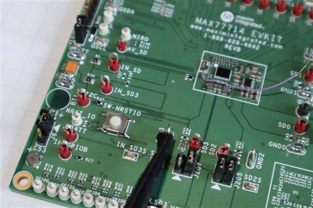
None of the registers changed in the EVK GUI. I proceeded to measure the voltage on the NRST_IO test point and the level on the test point remained high at 1.8 V (VLOGIC).


image

A short video pushing the button (I can't believe this is what I am Road Testing with a Maxim EVK).

You don't have permission to edit metadata of this video.
Edit media
x
image
Upload Preview
image


At which point I disconnected the backup battery and micro-USB cable to power cycle the board (I am powering the board via USB minus one diode drop with jumper J103 shorted), which most certainty did cause the MAX77714 to power on reset when I reconnected the USB cable.


This has me really spooked. Why would both push buttons be defective, the BOM for the EVK lists Panasonic EVQ-Q2K03WEVQ-Q2K03W push buttons.

image


image

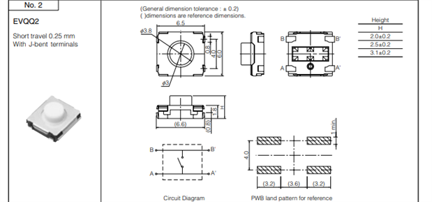
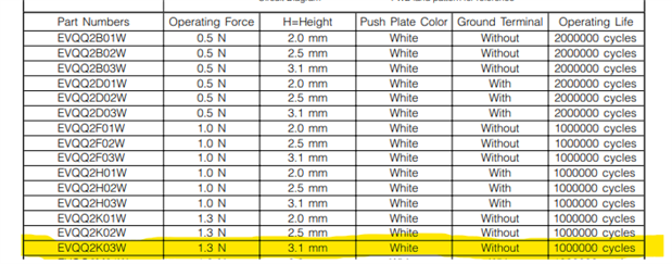
The dimensions of the buttons on the board match the datasheet specifications 6.0 x 6.5 x 3.1 mm, so I assume these are the genuine parts.


I measured continuity from A to A' and B to B', but could not get the button to actuate.


Why would a push button fail like this?


Should I try to clean them or tear them apart to see what went wrong?


Update #1

I decide I would go straight to a failure analysis without cleaning or desoldering the component. I lifted the top metal shield/cage of the button off first.

image


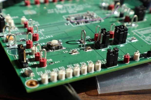
Inside the push button:

image

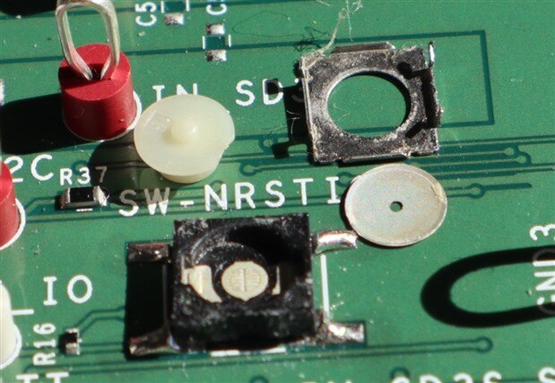
I can ring-out gnd continuity on the center pad and nrst continuity on the left and right pads. I don't get continuity when applying a very light pressure with my multimeter probe, so perhaps the contacts are oxidized or dirty. The dome doesn't appear like it has ever made contact to the center pad, perhaps that's normal. I will try cleaning the contact surfaces and see what happens.


Update #2

Just as @kmikemoo suggested in the comments, the switch contacts were indeed dirty. I captured in a single take video the second switch coming to life: https://youtu.be/LOSyaA2UKl4 with the application of some isopropyl alcohol.


I really don't know what to say. It's not like this board has lived a hard life on the shelf at Maxim or Newark, So, I would not have expected to these push button switches to fail so early.


I now have working push buttons!

  • Sign in to reply
  • dougw
    dougw over 4 years ago

    The way that schematic switch symbol is drawn, you would need to connect pin 3 to pin 4 or pin 2 to pin 1.

    These connections are usually inside such a switch, but the symbol doesn't show it.

    Perhaps worth checking if pin 3 is connected to pin 4 and pin 2 to pin 1.

    • Cancel
    • Vote Up 0 Vote Down
    • Sign in to reply
    • More
    • Cancel
  • scottiebabe
    scottiebabe over 4 years ago in reply to fmilburn

    Yes, although I used the ammeter mode of my multimeter to measure the pull-up current of the 100k resistor. Even more interesting in a way that makes sense is the reset pin is an input/output. So when the MAX77714 enters its reset procedure it also drives nrst low, until it is ready to come out of reset. So, I would see the current shorting nrst to ground toggle between 18 uA and ~ 0 uA as the PMIC reset cycled.


    <buzz for continuity when the MCU isn’t powered>

    This threw me off for a few minutes too. With the board unpowered the nrst line had a continuity of 0 ohms. However, this actually is correct because there is a 100 uF tantalum on the MBATT input to the PMIC and when the PMIC enters an VBATT UVLO it asserts the reset line low and has a very low quiescent current and can hold up for a few minutes running on the 100 uF input capacitor. But eventually the 100 uF capacitor discharges and the rst line reads an open (100k pull-up and esd diodes).

    • Cancel
    • Vote Up 0 Vote Down
    • Sign in to reply
    • More
    • Cancel
  • ralphjy
    ralphjy over 4 years ago

    Not that it's your problem, but that's really an odd schematic symbol for your switch.


    I would do a close inspection of the switch attachment.  From your picture the solder fillets on the pads don't look very good.  It looks like the switches were manually soldered rather than reflowed.  That could be a problem getting good attachment with a J terminal.

    • Cancel
    • Vote Up 0 Vote Down
    • Sign in to reply
    • More
    • Cancel
  • fmilburn
    fmilburn over 4 years ago

    Strange.  You may have already done this but can you jumper across the switch contacts with wire and see if that causes reset?  What happens if you buzz for continuity when the MCU isn’t powered and push the switch?

    • Cancel
    • Vote Up 0 Vote Down
    • Sign in to reply
    • More
    • Cancel
<
element14 Community

element14 is the first online community specifically for engineers. Connect with your peers and get expert answers to your questions.

  • Members
  • Learn
  • Technologies
  • Challenges & Projects
  • Products
  • Store
  • About Us
  • Feedback & Support
  • FAQs
  • Terms of Use
  • Privacy Policy
  • Legal and Copyright Notices
  • Sitemap
  • Cookies

An Avnet Company © 2026 Premier Farnell Limited. All Rights Reserved.

Premier Farnell Ltd, registered in England and Wales (no 00876412), registered office: Farnell House, Forge Lane, Leeds LS12 2NE.

ICP 备案号 10220084.

Follow element14

  • X
  • Facebook
  • linkedin
  • YouTube