


In the last blog I took an overview approach to the MIT420/2MIT420/2 Insulation Tester package that I have been sent to review In this blog I plan to concentrate on the instrument itself to review its build quality and design features
To gain access inside the meter, the battery and fuse compartment lids are removed. As these are subject to more wear and tear, Megger have used steel screws captivated within each compartment lid that screw into brass inserts in the meter body which should provide a high level of reliability. There are four screws in the corners of the top section of the instrument and removal of the batteries reveals a fifth. These are self-tapper style screws, that screw into plastic holdings and are not as robust as the compartment lid screws. But as the case will be rarely opened, I don't view this as being an issue.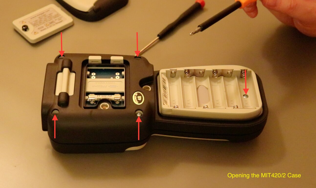
The top and bottom parts of the case are separated by pulling them apart. There is a bit of resistance when doing this as there is a lip style seal around the whole of the case to protect against moisture and dirt ingress. Once the seal is split, the case comes apart easily. The battery connects to the board inside via two spring tabs so there are no wires to disconnect. Interestingly there is no shielding inside any of the case components.
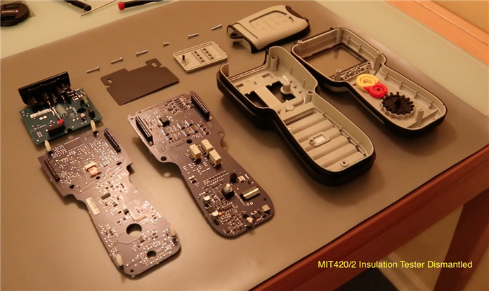
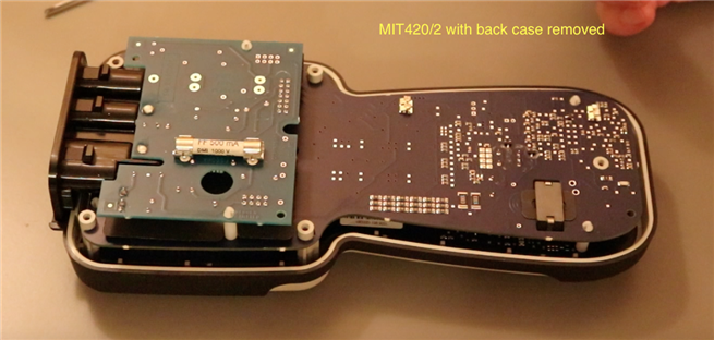
With the bottom case removed, the internal electronics is spread across three PCBs giving a modular design. The PCBs connect together electrically through header connectors and are mechanically joined by plastic spacers that push through holes to clip the boards in place. The complete assembly is held into the top case via a single screw just below the function buttons. Removing this allows the PCBs to be removed.
The top case contains a clear perspex screen to protect the display, the rubberised function buttons and the rotary selector switch mechanism.
The display is mounted on the front PCB via clips and is connected electrically via a ribbon cable onto the rear of the PCB. The processor electronics appear to be underneath the display and whilst the display unclips from the PCB easily enough, I couldn't release the ribbon cable from its socket and didn't want to use too much force incase clumsy thumbs broke something.
The rest of the front face of the PCB is fairly open. Directly beneath the display are the PCB tracks for the function buttons that are the silicone membrane variety with the carbon contact pad. Beneath these, the main test button was found to be an actual PCB mounted push switch, presumably to give more reliability for the button that will be see the highest number of operations. The OK button beneath this was found to be the track pad design as per the other function buttons.
The opposite side of this board contained a lot more electronics, but as I am not much of an electronics engineer and even less of a metrologist, there is not much on there that I recognised.
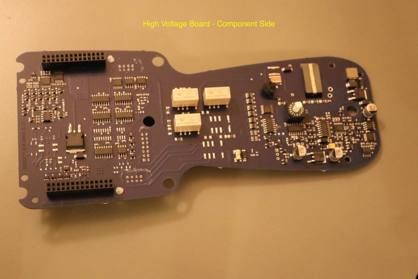
The next board in the stack appeared to contain the main high voltage amplifier circuit along with some selection relays. The main PCB track that carries the high voltage to the output terminal seems to be well spaced from the other components and tracks on the PCB but did not have any isolation slots around it. The track does go to an eight way PCB header that formed the connection through to the small output board. Only two other pins were used on this header at the opposite end for the control probe connections.
It was also noted that the rotary selector switch was a manufactured coded rotary hexadecimal switch, again presumably chosen to giver a higher robustness to the design instead of the more standard PCB track design function switches found in multimeters.


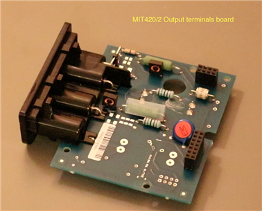
The final board is much smaller than the other two boards and is segregated from the middle board via an insulation sheet that locates around the header connectors and PCB spacers. This board primarily contains the 500mA HRC fuse and the 4mm safety connectors contained within a plastic moulding. The plastic moulding has location lugs to go onto the PCB and then the sockets are soldered onto the PCB through a right-angled pin. This design seems to offload a lot of the mechanical pressure into the plastic moulding when inserting and removing the leads, this should provide protection for the actual solder joints and shows good design by Megger.
The 500mA HRC fuse was of great interest to me due to the high energy circuits that I work on Tracing through the tracks on the PCB showed that the fuse is directly in circuit with the positive terminal of the insulation tester There was a thinner track between the fuse and the terminal that led to a 10MOhm resistor that bypasses the fuse I couldn't work out what the function of this was but I got the impression that the fuse protects all of the functions on the tester If so this is quite impressive as I am not aware of any other insulation testers that have this level of fusing I will investigate this more when the MIT420/2MIT420/2 is reassembled There also appears to be space on the PCB for a second fuse presumably for the three terminal insulation tester offered as part of the range that adds a guard terminal to the instrument
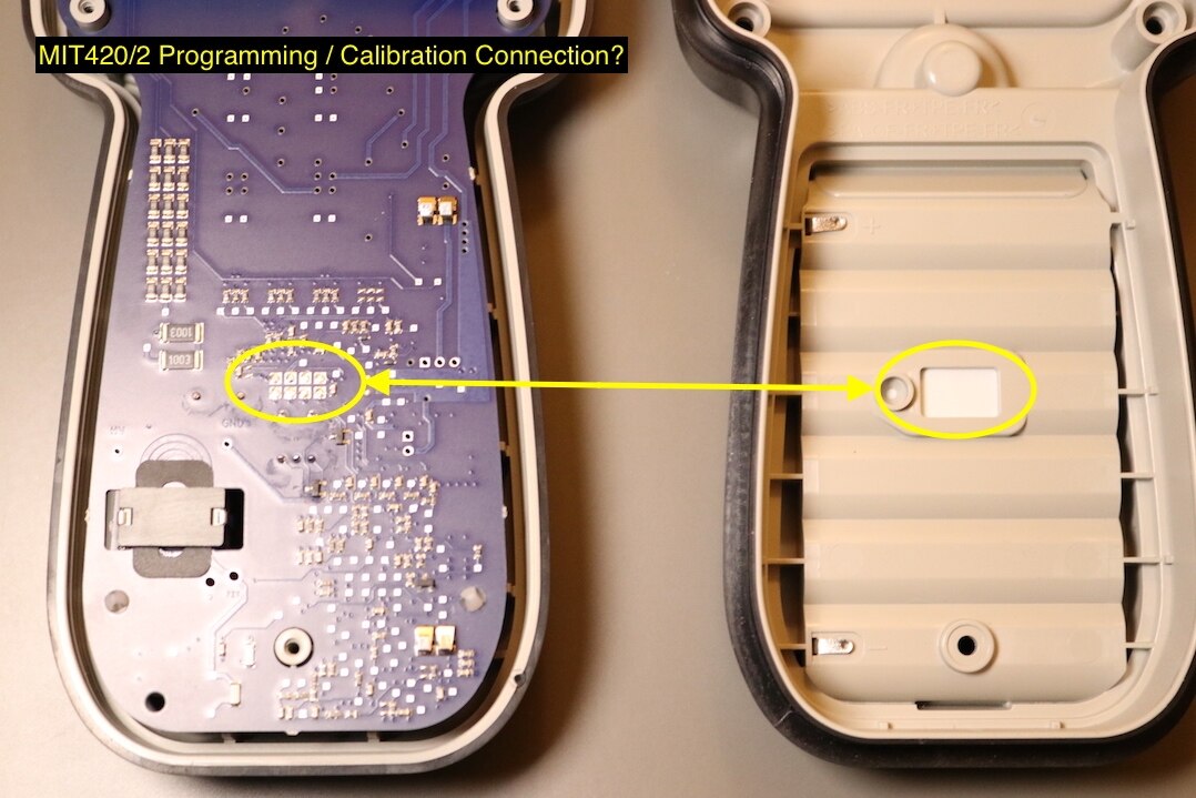
During the reassembly of the instrument, I noticed a cutout in the battery case compartment covered over by a sticker. This cutout lines up with eight pads on the rear of the high voltage board. Unlike other manufacturer's, I have never seen a service manual for an instrument from Megger, to find out what the calibration procedure is. There does not appear to be anything obvious within the setting menu, so seeing this cutout made me wonder if there is some bespoke test system that connects to the instrument through this cutout to allow the meter calibration to be adjusted. If this is the case, and I am not certain of this, this would limit places where the instrument can have its calibration adjusted. Granted, the majority of calibration laboratories could check that the instrument is working within tolerances, but maybe it has to go back direct to Megger, or one of their partners, to be adjusted.
Overall, the meter construction is of good quality with some interesting safety features. The instrument has a good modular design, allowing for replacement of individual PCBs. There is no evidence of post design modifications on any of the boards. The instrument case is strong with a built in rubberised coating. Robust design features such as threaded inserts and manufactured switches are utilised in areas where reliability through extensive use may become an issue.
In the next blog I will move on to carrying out some bench tests with the MIT420/2MIT420/2
