


Up to this point the on site tests carried out with the MIT420/2MIT420/2 have been based around motor tests either from a control centre or direct at the motor terminals Unsurprisingly the instrument has performed very well with the only issues really being around making connections to specific items during the earth test on a large motor and when using the supplied test lead to short out the winding after the tests These are all minor issues and relatives easy to overcome
This blog introduces the testing of air circuit breakers (ACBs). These are large three phase, low voltage breakers design to switch high currents. Although only rated to 690V AC, due to their robust construction and the types of insulation utilised, we often test them at 1000V, which is a test range that has not been utilised out on site yet with the instrument.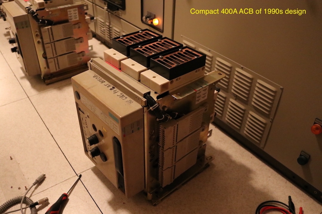
The added benefit of the 1000V range on the MIT420/2MIT420/2 is the it will measure up to 200GOhm resistance value which will be more likely to pickup carbon contamination from arcing as the breaker operates
If this was routine planned maintenance being performed on the ACBs then a suite of visual inspections mechanical measurements electrical and timing tests would be completed but as this is mainly for demonstrating the use of the MIT420/2MIT420/2 I will only be checking that the main contacts have closed using the continuity resistance function and checking the insulation resistance from phase to earth phase to phase and across the open contacts using the 1000V range
As the type of insulation and assembly methods differs to that of a motor or a cable, a dielectric absorption or polarisation index is not applicable and only a 1 minute timed test is conducted, the reading will be expected to ramp up to its final resistance value within seconds, and stay there for the duration of the test.
I have two types of ACBs available to me to test. One is a relatively modern design and is more compact and includes a built in protection relay. The second one is a much more older design and sits in a much larger metallic frame with greater clearances. The principle of their operation however, is the same, and they are tested with an insulation tester in exactly the same manner.
The first aspect of testing an ACB, is to make it safe. Electrically, the ACB is isolated by removing it from its carriage where it can then be placed on the floor or a maintenance trolley. As the ACBs use a powerful spring to close and trip the main contacts, a significant amount of stored mechanical energy remains within the unit that is discharged by closing the breaker. I can then make the breaker safe by inserting a safety pin into the ACB frame to lock the tripping mechanism for carrying out the first set of insulation tests, to earth and between phases, with the contacts closed. This is done so that I am insulation testing the complete primary circuit of each phase and do not have to test each contact individually. Once these tests are complete, I can remove the safety pin and trip the ACB open. This will remove all stored mechanical energy in the ACB and the mechanism will be safe to work on.
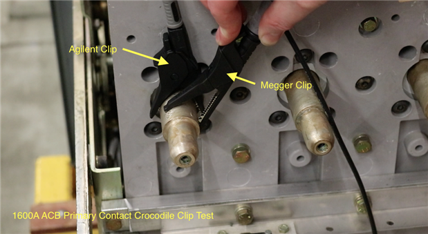
The following video shows an older style 1600A air circuit breaker being tested. As you will see I had a slight issue with the crocodile clips on the Megger leads that would not grip around the primary contact, so I had to resort to using the leads and crocodile clips from another manufacturer. Other than this slight issue, the tests went well with all results at the 200GOhms maximum reading, showing that the insulation is in excellent condition and there is little contamination.
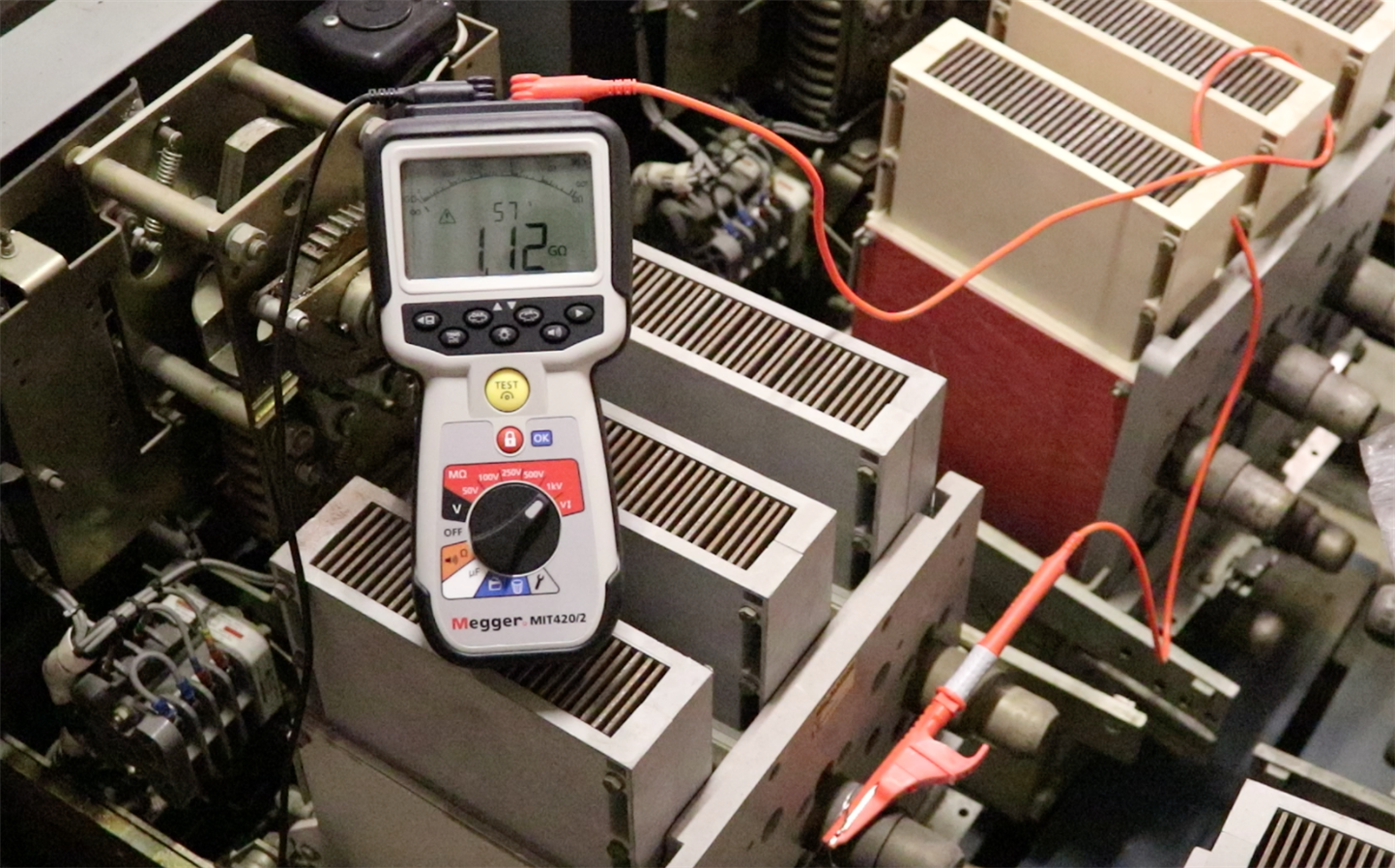
A test on a 4000A breaker shows a different story, with a much lower reading being achieved, indicating that there was contamination across the contact in this breaker. With the primary contact having an even bigger diameter than a 1600A contact, I had to resort to the large crocodile clips from my Fluke 1555C insulation tester to make the connections, but the photo below shows an alternative arrangement using tinned copper wire to wrap around the contact and twist tight. The Megger crocodile clip can then be clipped to this which gives a perfectly adequate test connection for a voltage test with a low output current.
This concludes the blog, the instrument has performed perfectly well and continues to be reliable and easy to use.
The next blog will be the final installment on testing a generator rotor winding.