element14 Community
element14 Community
    Register Log In
  • Site
  • Search
  • Log In Register
  • Community Hub
    Community Hub
    • What's New on element14
    • Feedback and Support
    • Benefits of Membership
    • Personal Blogs
    • Members Area
    • Achievement Levels
  • Learn
    Learn
    • Ask an Expert
    • eBooks
    • element14 presents
    • Learning Center
    • Tech Spotlight
    • STEM Academy
    • Webinars, Training and Events
    • Learning Groups
  • Technologies
    Technologies
    • 3D Printing
    • FPGA
    • Industrial Automation
    • Internet of Things
    • Power & Energy
    • Sensors
    • Technology Groups
  • Challenges & Projects
    Challenges & Projects
    • Design Challenges
    • element14 presents Projects
    • Project14
    • Arduino Projects
    • Raspberry Pi Projects
    • Project Groups
  • Products
    Products
    • Arduino
    • Avnet Boards Community
    • Dev Tools
    • Manufacturers
    • Multicomp Pro
    • Product Groups
    • Raspberry Pi
    • RoadTests & Reviews
  • Store
    Store
    • Visit Your Store
    • Choose another store...
      • Europe
      •  Austria (German)
      •  Belgium (Dutch, French)
      •  Bulgaria (Bulgarian)
      •  Czech Republic (Czech)
      •  Denmark (Danish)
      •  Estonia (Estonian)
      •  Finland (Finnish)
      •  France (French)
      •  Germany (German)
      •  Hungary (Hungarian)
      •  Ireland
      •  Israel
      •  Italy (Italian)
      •  Latvia (Latvian)
      •  
      •  Lithuania (Lithuanian)
      •  Netherlands (Dutch)
      •  Norway (Norwegian)
      •  Poland (Polish)
      •  Portugal (Portuguese)
      •  Romania (Romanian)
      •  Russia (Russian)
      •  Slovakia (Slovak)
      •  Slovenia (Slovenian)
      •  Spain (Spanish)
      •  Sweden (Swedish)
      •  Switzerland(German, French)
      •  Turkey (Turkish)
      •  United Kingdom
      • Asia Pacific
      •  Australia
      •  China
      •  Hong Kong
      •  India
      •  Korea (Korean)
      •  Malaysia
      •  New Zealand
      •  Philippines
      •  Singapore
      •  Taiwan
      •  Thailand (Thai)
      • Americas
      •  Brazil (Portuguese)
      •  Canada
      •  Mexico (Spanish)
      •  United States
      Can't find the country/region you're looking for? Visit our export site or find a local distributor.
  • Translate
  • Profile
  • Settings
RoadTests & Reviews
  • Products
  • More
RoadTests & Reviews
Blog NGU401: Regulation Tests
  • Blog
  • RoadTest Forum
  • Documents
  • RoadTests
  • Reviews
  • Polls
  • Files
  • Members
  • Mentions
  • Sub-Groups
  • Tags
  • More
  • Cancel
  • New
Join RoadTests & Reviews to participate - click to join for free!
  • Share
  • More
  • Cancel
  • Author Author: neuromodulator
  • Date Created: 10 Sep 2021 11:19 PM Date Created
  • Views 614 views
  • Likes 6 likes
  • Comments 1 comment
Related
Recommended

NGU401: Regulation Tests

neuromodulator
neuromodulator
10 Sep 2021

Introduction


To explore the regulation capabilities of the SMU I performed a few tests to see how it behaved in voltage priority mode (VPM), current priority mode (CPM), and in the (voltage) modulation mode. Let's briefly explain what all this modes are. VPM is the standard operation mode of power supplies, in this mode, the SMU starts in constant voltage (CV) (i.e., the SMU control loop regulates the voltage), so there is very little voltage overshoot. The SMU stays in CV unless the current limit is hit, and if this happens, it switches to constant current (CC). This is not instantaneous and during the transition from CV to CC the current can overshoot. CPM works the opposite way, the SMU starts in CC, and if the voltage limits get hit, the voltage can overshoot as it transitions to CV.


In the modulation mode the SMU acts like a voltage amplifier. In this mode the SMU takes the signal that is fed into the back panel connectors MOD- and MOD+ and amplifies with a gain of either 0.5, 1 or 2.


Voltage priority mode


I used the instrument's arbitrary function generator to generate a 10 ms pulse sweep from -20 V to +20 V in 0.5 V steps under different fast transient response settings (FTR) and loads. 4 tests were performed:

  1. Open circuit, FTR off
  2. Open circuit, FTR on
  3. 8 Ω load, FTR off
  1. 8 Ω load, FTR on


Recordings are displayed in 2 different ways:

  1. As a voltage and current time series
  2. As time-stacked voltage time series


imageimage

imageimage

imageimage

imageimage


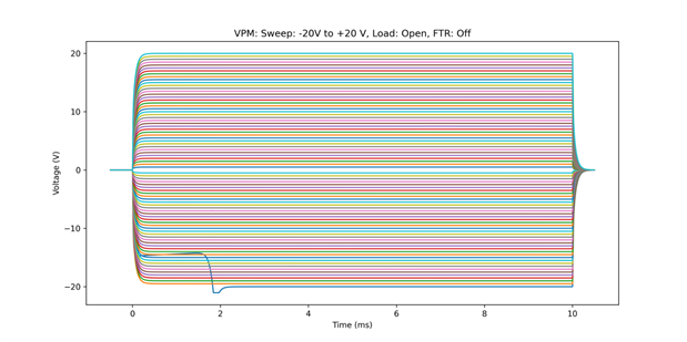
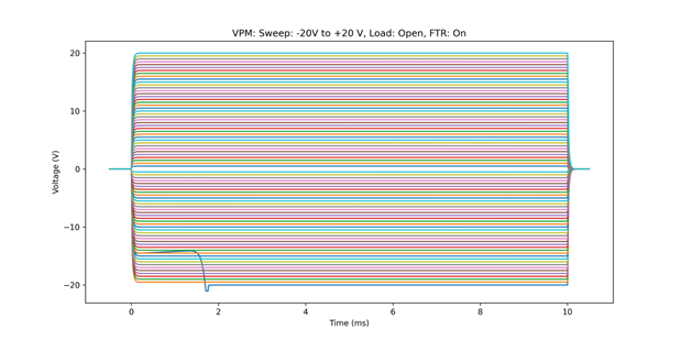
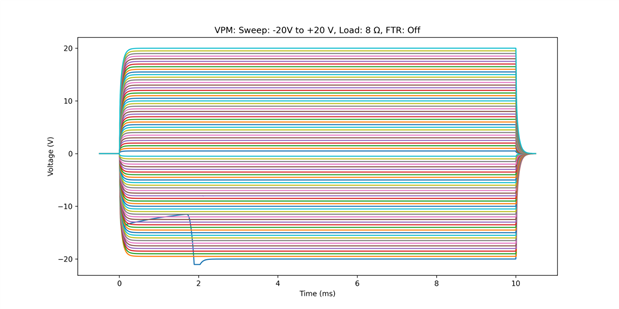
As expected FTR increased the regulation speed, but at the cost of minor overshoots under 8 Ω load. These overshoots appeared to vary across repetitions of the test. One relevant regulation "glitch" occurred in all tests during the first pulse, where it took the SMU ~2 ms to reach the set voltage. This issue even though, highly repeatable in all tests, did not occur when the sweep began with positive pulses (from +20 V to - 20V). Note also that there are current spikes in the open circuit tests, these are caused by the SMU's output capacitor.


Current Priority Mode


In a similar way I tested the SMU in CPM under a short and ~0.3 Ω while performing a pulsed sweep from -8 A to 8 A in 0.5 A steps. Note that there are no FTR settings in CPM.


imageimage

imageimage


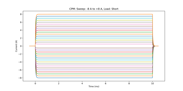
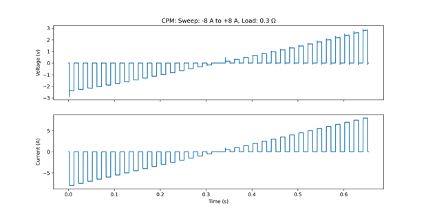
In both test the current regulation performed fairly well, with the exception of some overshooting during the 0.5 A pulse.


CPM Load Regulation


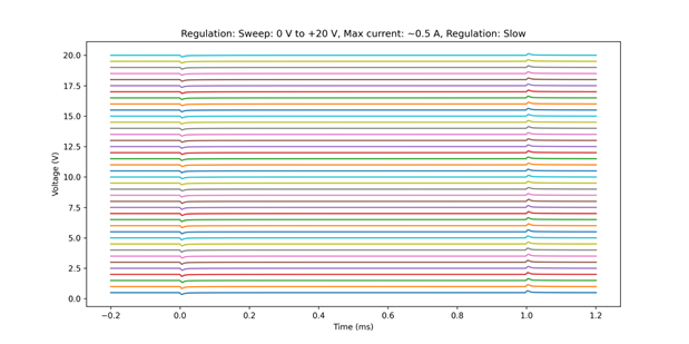
To test load regulation capabilities I performed a stepped voltage sweep from 0 V to either 6 V or 20 V (depending on the tested current load) in 0.5 V steps. The stepped sweep was performed using the instrument's AFG capability, while the 1 ms load pulses were generated with an "improvised e-load" made of an n-FET load connected to an (external) AFG. 6 conditions were tested:

  1. Max current ~0.5 A, FTR off
  2. Max current ~0.5 A, FTR on
  3. Max current ~3 A, FTR off
  4. Max current ~3A, FTR on
  5. Max current ~8A, FTR off
  6. Max current ~8A, FTR off


In addition to the raw voltage and current time series and the time-stacked voltage time series, I also plotted the time-voltage-stacked time series to better visualize the voltage dip and voltage swell.


imageimageimage


imageimageimage

imageimageimage

imageimageimage

imageimageimage

imageimageimage


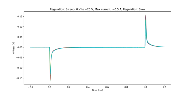
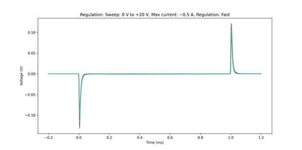
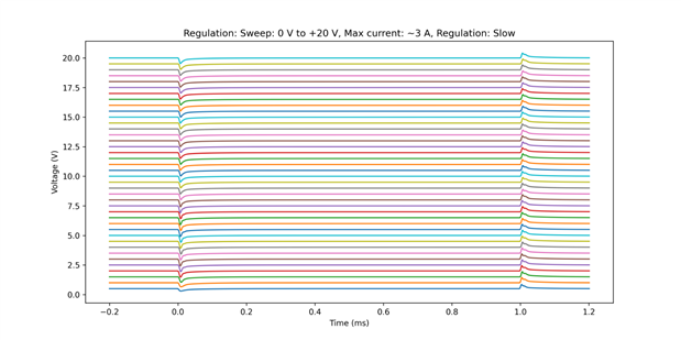
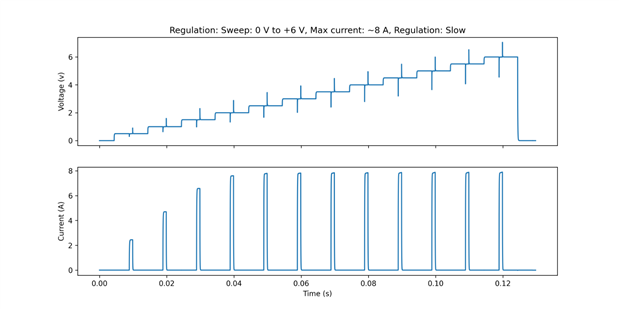
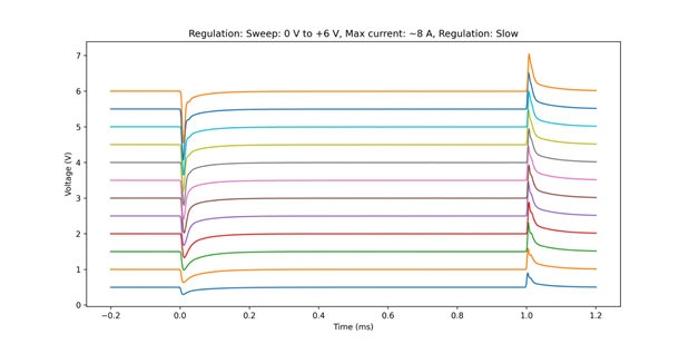
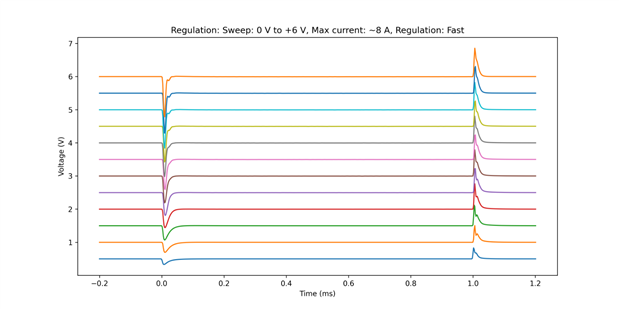
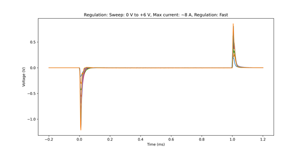
The results were all as expected, FTR reduced the regulation time and the deviation from the voltage setting, and the higher the current the bigger the dip and swell. Even though the test conditions were very extreme, as current switched from almost 0 to 0.5, 3 or 8A, these test still show us what we can expect under different load conditions.


Modulation


To test the modulation mode I connected an external AFG to the MOD- and MOD+ back panel connectors. The AFG was set to generate sine waves of 10 Vpp at 1 Hz, 10 Hz, and 100 Hz. The SMU gain was set to 1 and a load of 4 Ω was connected to the output.

imageimageimage


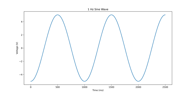
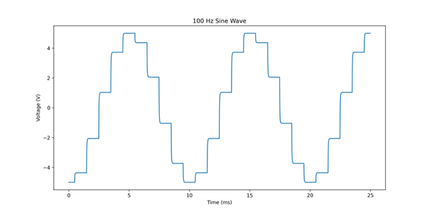
As it can be seen, the signal is sampled at 1 kHz. I also noticed that no low pass filtering is applied, so care must be taken to avoid aliasing. One minor issue that I found is that every 100 samples (or ms), one sample "steals" dwell time of the next sample. This can be seen in the 10 Hz plot at around 95 and 195 ms.

  • Sign in to reply
  • DAB
    DAB over 3 years ago

    Nice post.


    DAB

    • Cancel
    • Vote Up 0 Vote Down
    • Sign in to reply
    • More
    • Cancel
element14 Community

element14 is the first online community specifically for engineers. Connect with your peers and get expert answers to your questions.

  • Members
  • Learn
  • Technologies
  • Challenges & Projects
  • Products
  • Store
  • About Us
  • Feedback & Support
  • FAQs
  • Terms of Use
  • Privacy Policy
  • Legal and Copyright Notices
  • Sitemap
  • Cookies

An Avnet Company © 2025 Premier Farnell Limited. All Rights Reserved.

Premier Farnell Ltd, registered in England and Wales (no 00876412), registered office: Farnell House, Forge Lane, Leeds LS12 2NE.

ICP 备案号 10220084.

Follow element14

  • X
  • Facebook
  • linkedin
  • YouTube