element14 Community
element14 Community
    Register Log In
  • Site
  • Search
  • Log In Register
  • Community Hub
    Community Hub
    • What's New on element14
    • Feedback and Support
    • Benefits of Membership
    • Personal Blogs
    • Members Area
    • Achievement Levels
  • Learn
    Learn
    • Ask an Expert
    • eBooks
    • element14 presents
    • Learning Center
    • Tech Spotlight
    • STEM Academy
    • Webinars, Training and Events
    • Learning Groups
  • Technologies
    Technologies
    • 3D Printing
    • FPGA
    • Industrial Automation
    • Internet of Things
    • Power & Energy
    • Sensors
    • Technology Groups
  • Challenges & Projects
    Challenges & Projects
    • Design Challenges
    • element14 presents Projects
    • Project14
    • Arduino Projects
    • Raspberry Pi Projects
    • Project Groups
  • Products
    Products
    • Arduino
    • Avnet Boards Community
    • Dev Tools
    • Manufacturers
    • Multicomp Pro
    • Product Groups
    • Raspberry Pi
    • RoadTests & Reviews
  • Store
    Store
    • Visit Your Store
    • Choose another store...
      • Europe
      •  Austria (German)
      •  Belgium (Dutch, French)
      •  Bulgaria (Bulgarian)
      •  Czech Republic (Czech)
      •  Denmark (Danish)
      •  Estonia (Estonian)
      •  Finland (Finnish)
      •  France (French)
      •  Germany (German)
      •  Hungary (Hungarian)
      •  Ireland
      •  Israel
      •  Italy (Italian)
      •  Latvia (Latvian)
      •  
      •  Lithuania (Lithuanian)
      •  Netherlands (Dutch)
      •  Norway (Norwegian)
      •  Poland (Polish)
      •  Portugal (Portuguese)
      •  Romania (Romanian)
      •  Russia (Russian)
      •  Slovakia (Slovak)
      •  Slovenia (Slovenian)
      •  Spain (Spanish)
      •  Sweden (Swedish)
      •  Switzerland(German, French)
      •  Turkey (Turkish)
      •  United Kingdom
      • Asia Pacific
      •  Australia
      •  China
      •  Hong Kong
      •  India
      •  Korea (Korean)
      •  Malaysia
      •  New Zealand
      •  Philippines
      •  Singapore
      •  Taiwan
      •  Thailand (Thai)
      • Americas
      •  Brazil (Portuguese)
      •  Canada
      •  Mexico (Spanish)
      •  United States
      Can't find the country/region you're looking for? Visit our export site or find a local distributor.
  • Translate
  • Profile
  • Settings
RoadTests & Reviews
  • Products
  • More
RoadTests & Reviews
Blog Part 3: Static/Dynamic Load Testing [Updated: 10 Jan 2021]
  • Blog
  • RoadTest Forum
  • Documents
  • RoadTests
  • Reviews
  • Polls
  • Files
  • Members
  • Mentions
  • Sub-Groups
  • Tags
  • More
  • Cancel
  • New
Join RoadTests & Reviews to participate - click to join for free!
  • Share
  • More
  • Cancel
  • Author Author: waleedelmughrabi
  • Date Created: 22 Dec 2020 8:52 PM Date Created
  • Views 898 views
  • Likes 4 likes
  • Comments 5 comments
Related
Recommended
  • desktop power supply
  • r&s
  • power supplies

Part 3: Static/Dynamic Load Testing [Updated: 10 Jan 2021]

waleedelmughrabi
waleedelmughrabi
22 Dec 2020

Part 3 of R&S NGP814 Power Supply - Review


Static Load:


Two chassis mount resistive loads from TE were used for these tests. They are wirewound resistors in a large ceramic core, they have many uses, I have a few that I use as a dump load while testing capacitor banks, rail-gap switches and inverters.

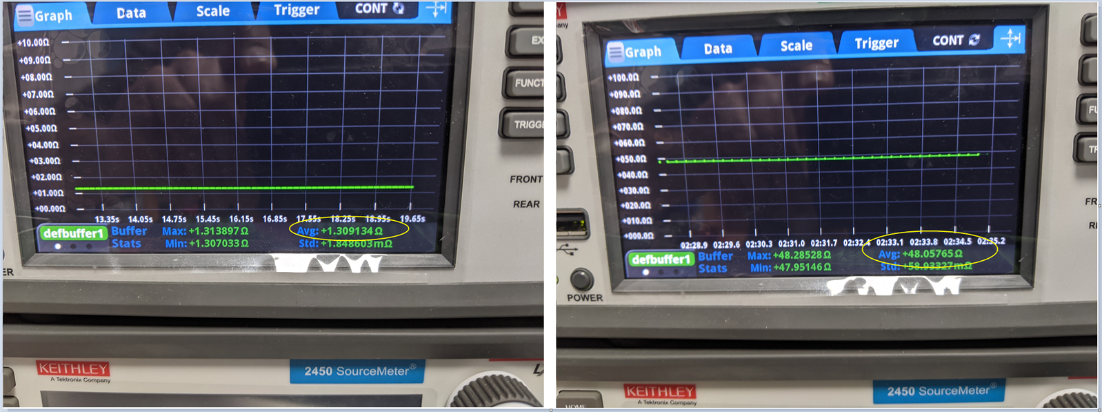
The first resistor is supposed to be 1ohm with 5% tolerence but it is measured at 1.3 ohm, the second is 47 ohm 5% measured at 48.05765 ohm as seen in the photos below.

image


Part A: Series Combination


image

Resistor used: 48.05765 ohm

Current = 2.644265 A

I ripple p-p = 2.647849 - 2.640457 = 7.392 mA


Voltage = 127.9272 V

V ripple p-p = 127.9281 - 127.9262 = 1.9 mV


The video below shows the test set up, the touch screen is very useful to change various parameters to cut down testing time.

The delayed output feature can help to monitoring performance and efficiency of voltage regulators and DC-DC converters at different voltage windows.


You don't have permission to edit metadata of this video.
Edit media
x
image
Upload Preview
image


Part B: Parallel Combination


image


Resistor used: 1.3 ohm

Voltage = 19.00135 V

V ripple p-p = 19.00181 - 19.00117 = 0.64 mV


You don't have permission to edit metadata of this video.
Edit media
x
image
Upload Preview
image


In the video above all channels are connected in parallel, I wanted to monitor the cutoff point at which the current limit is exceeded, in this case the ramp function came in handy. Voltage can be seen rising to reach steady state, and graphical view can also help when testing multiple devices to compare and observe their behaviour.

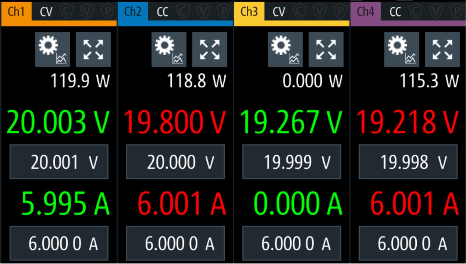
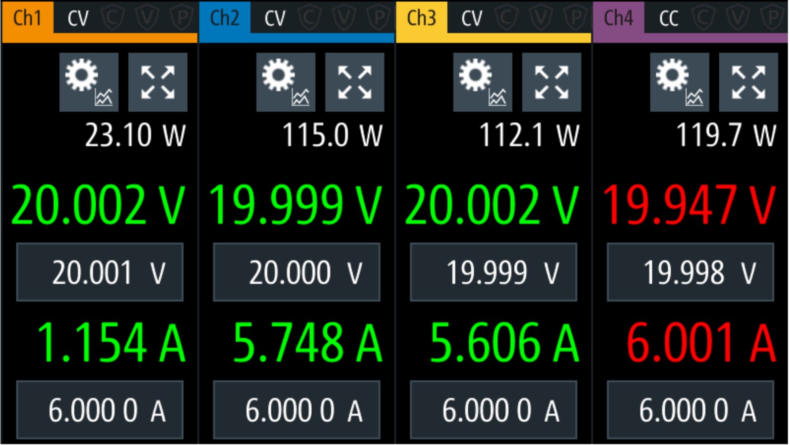
I noticed an issue with channel 3, no matter what voltage and current limit I set it does not output the same power as the other channels, so I tried a few other combinations and changed the limits to stay within operating range as seen in the photos below.


image


image


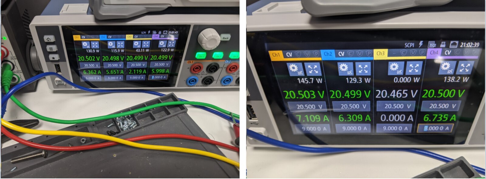
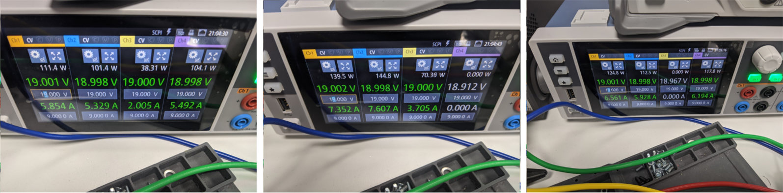
The photos above shows an unexpected behaviour, when channel 3 is switched off all other channels have a similar output. Whereas the current output of channel 3 is less than 50% of the other channels.

This will need further investigation, I need to look into all my cables that I am using and test again before contacting R&S support.


Dynamic Load and Logging Features:

The NGP800 series was designed with a 125 Samples/sec aquisition rate, which can be considered very limited compared to most mid/high range oscilloscopes/ DMM/ or data loggers, however it can be very helpful when a high sampling rate is not required. The example below is for a circuit used in monitoring industrial washers used to clean engine parts.


image

image


image


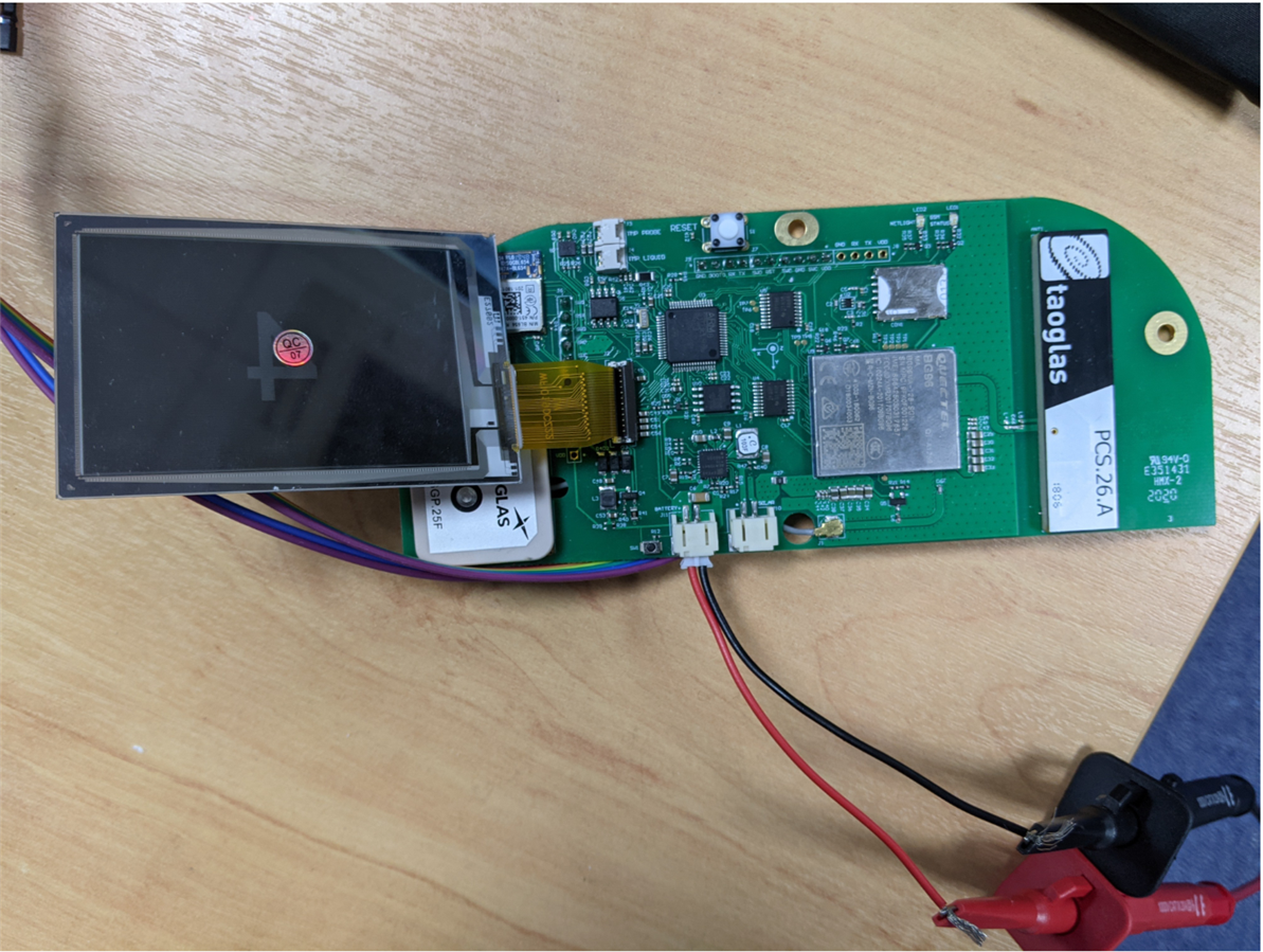
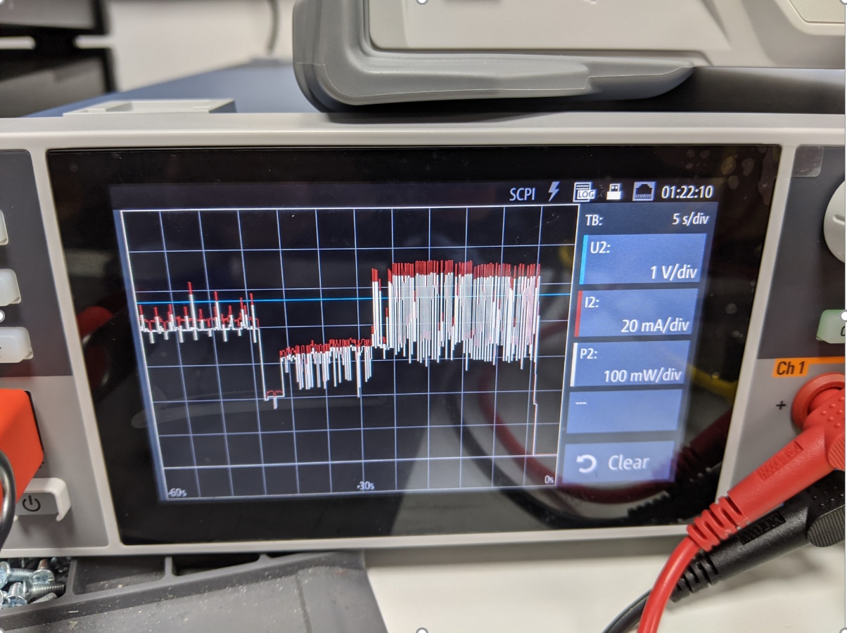
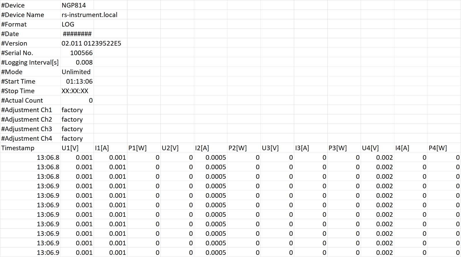
Considering that the device powered by the NGP814 is a low power device it might not be a good example to demonstrate and test the logging features, but the same concept and steps used can be applied to any type of dynamic loads that can be more suitable to the rated power and sampling rate of the NGP814. I agree with fellow raodtester gpolder that the "Graphical view" is limited, it will help to be able to zoom in and out or focus on a certain region and also the PC software does not support realtime viewing which can be helpful to pin down analysis to certain windows instead of having to save the whole session as a CSV file then analyse. One way around this will be to write a script or a labview code that will fetch data from the CSV to use for plots and further calculations.

Power measurements are also very useful for a system designer that wants to calculate energy usage, one integration formula for power measurements will show the energy consumption figure.


Update: 10 Jan 2021

Spent some more time trying different combinations for parallel connection. As Gough Lui mentioned in his comment and the screenshot he shared from a different series (R&S HMP4040) slight differences in voltage should distribute the load between channels more evenly.

I tried to shorten the jumper cables and make sure they are all same length to mitigate mismatch as much as possible then tried different combinations between channels to see changes in how the output power is distributed.


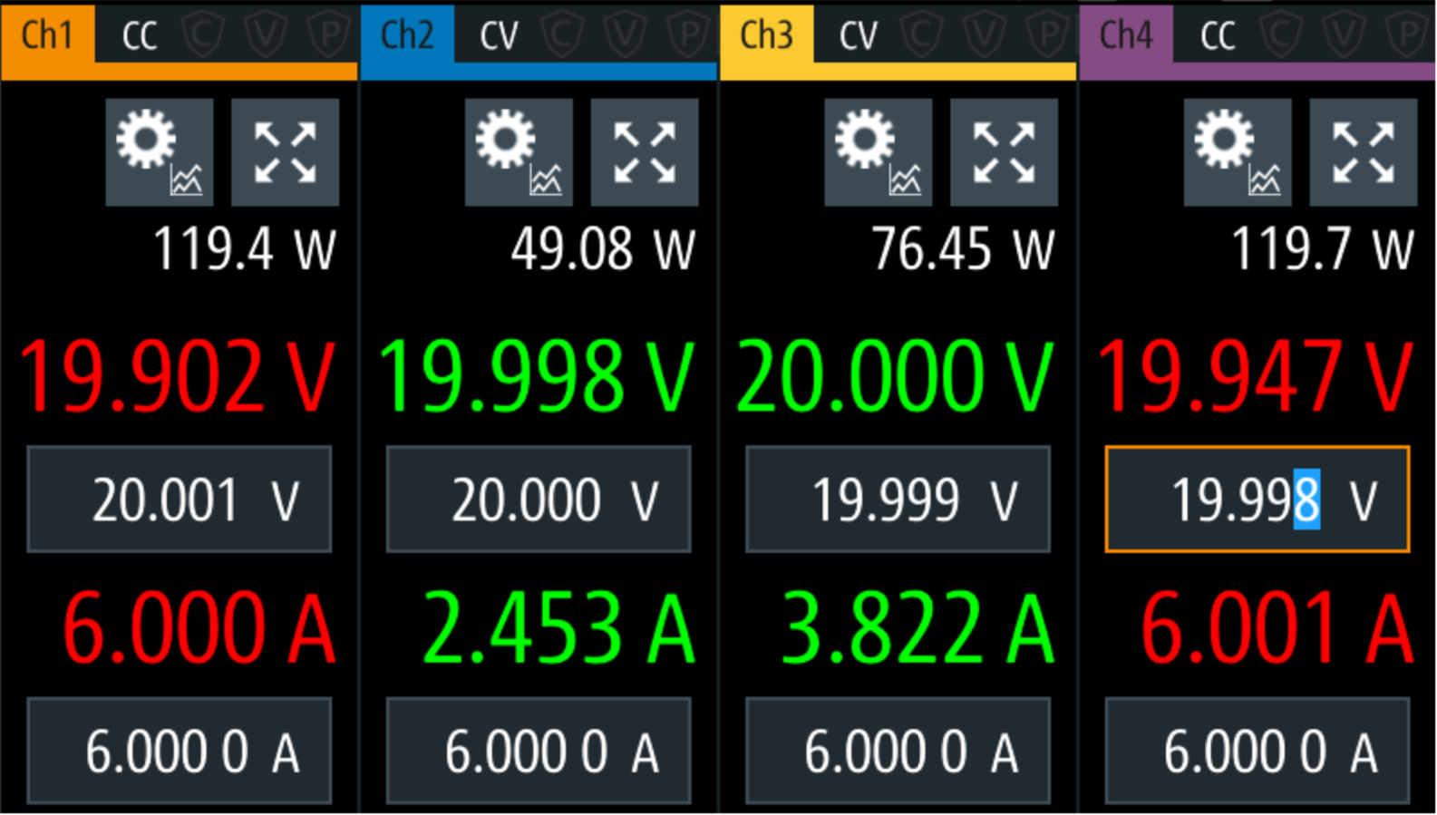
A- Variation of 1 mV

The channels were set at 20V with 1mV steps. 20.001, 20.000, 19.999, 19.998

The current output of every channel was not fully stable and kept going up and down by about 500mA. 
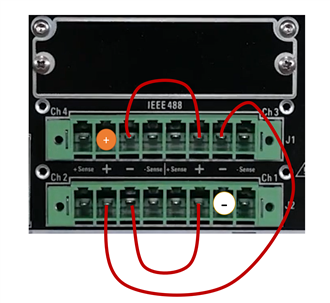
 

Positive -> Ch1+

Negative-> Ch4-

image


Positive -> Ch4+

Negative-> Ch2-

image


Positive -> Ch2+

Negative-> Ch3-

image


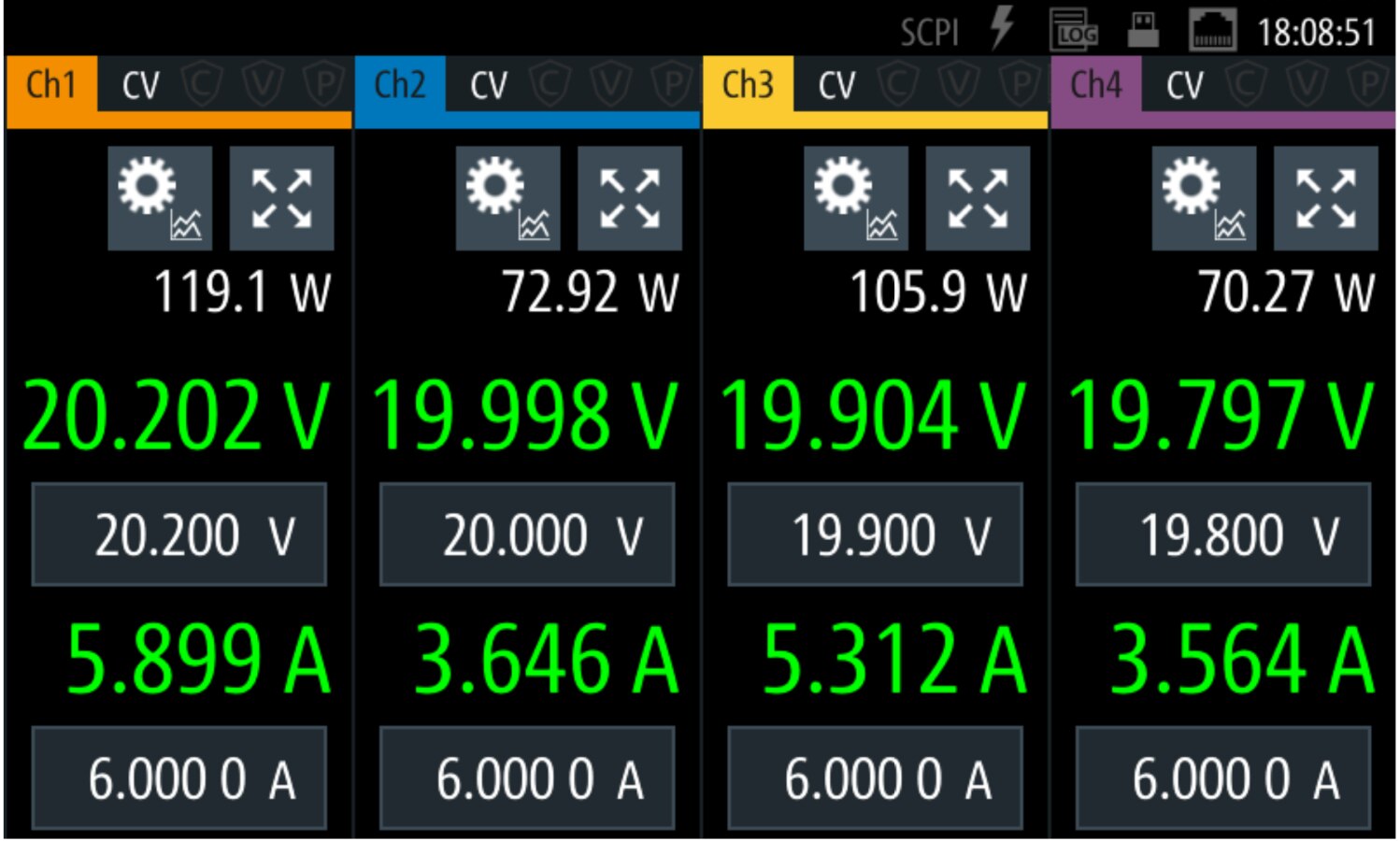
A- Variation of 100 mV

A stable output was achieved when the voltage difference changed by 100mV. It was not a perfect balance between the channels, but at least all channels were within the limits.

after about 10 seconds the output changed from the first photo below to the one shown in the second photo and then remained constant.
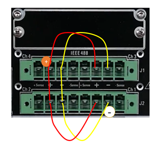
 

Positive -> Ch2+

Negative-> Ch3-

image

image


- As R&S mentioned, the load might not be evenly distributed between channels due to tolerences.

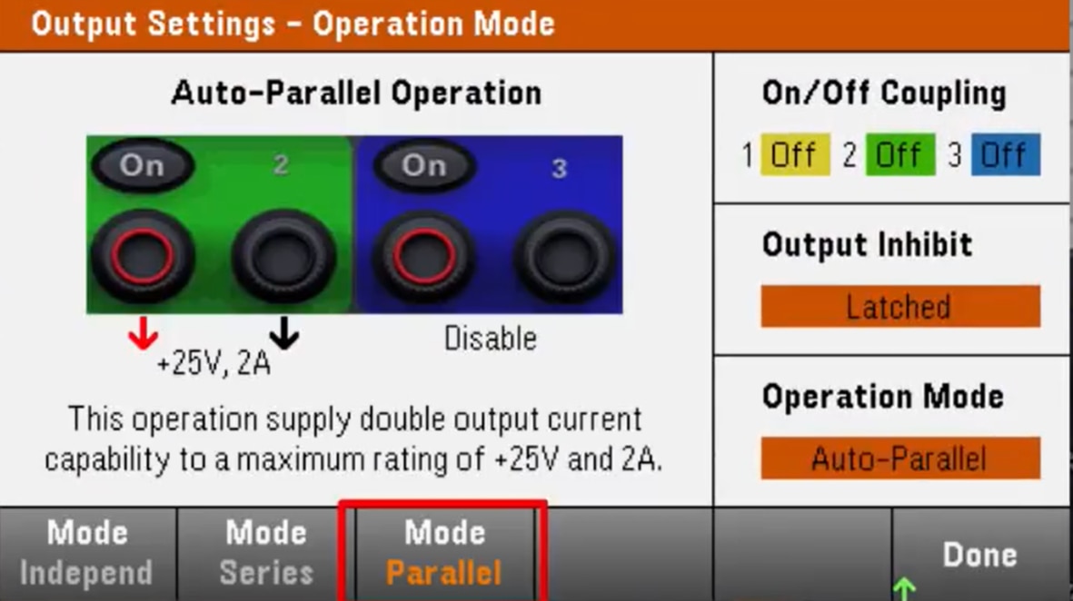
- What might be a useful feature is internal connections (a series/parallel mode like the Keysight E36300 like the photo below) to avoid using a lot of external cables and to minimize mismatch due to voltage drop in cables. 

image

  • Sign in to reply

Top Comments

  • Gough Lui
    Gough Lui over 4 years ago +5
    I don't believe R&S intended for the channels to be paralleled where the outputs are not of the same rating, although it should be possible provided the limits of the lowest capability channel are respected…
  • Gough Lui
    Gough Lui over 4 years ago +3
    Thanks for the update waleedelmughrabi . I'm not surprised that a variation of 1mV didn't do much - looking at the datasheet, Ch1/2 is specified for a programming accuracy of 0.05% + 5mV and Ch3/4 is specified…
  • Gough Lui
    Gough Lui over 4 years ago in reply to Andrew J +2
    Thanks @andrewj - glad to hear that you appreciated my feedback. You can probably tell that this is a RoadTest I was interested in and it is an area I have some knowledge about, so I couldn't hold back…
  • waleedelmughrabi
    waleedelmughrabi over 4 years ago in reply to Gough Lui

    Gough Lui it's not a diversion at all. Your input was very helpful and spot on (as always image  ) to get to the bottom of it, and make the most out of the roadtest. As you mentioned I did use different wires, when I first used the front panel I got slightly worse results than what is displayed. I then used thicker core wires (specs in the main review page) and used the rear panel, which helped get a more stable output.

    I am still looking into the calibration issue, but factory calibration is good (the difference between DMM and readback is a few uV at no load, and around 40uV max at full load).

    • Cancel
    • Vote Up +2 Vote Down
    • Sign in to reply
    • More
    • Cancel
  • Gough Lui
    Gough Lui over 4 years ago in reply to Andrew J

    Thanks @andrewj - glad to hear that you appreciated my feedback. You can probably tell that this is a RoadTest I was interested in and it is an area I have some knowledge about, so I couldn't hold back - of course I don't mean to cause unnecessary diversions for Waleed, but I just wanted to try and explain as much of the observations, share some of the knowledge I've gained in prior RoadTests/hobby experiments and understand just what is causing the reported issues. Sometimes you do need a little bit of extra thought to make the most of your gear, especially if it is high-end and you're expecting very fine accuracy.


    - Gough

    • Cancel
    • Vote Up +2 Vote Down
    • Sign in to reply
    • More
    • Cancel
  • Andrew J
    Andrew J over 4 years ago in reply to Gough Lui

    The two posts in this thread you made Gough are really useful.  I would never have known this without reading.

    • Cancel
    • Vote Up +1 Vote Down
    • Sign in to reply
    • More
    • Cancel
  • Gough Lui
    Gough Lui over 4 years ago

    Thanks for the update waleedelmughrabi.


    I'm not surprised that a variation of 1mV didn't do much - looking at the datasheet, Ch1/2 is specified for a programming accuracy of 0.05% + 5mV and Ch3/4 is specified for a programming accuracy of 0.05% + 10mV. Of course, in reality, a good unit (especially new) should do better than that - but this means that the actual output should be +/- 20mV of the set value. Likewise, the on-screen readback is only guaranteed to the same level of error. As a result, changing the output by 1mV probably wouldn't do much and that is borne out by your experiments.


    When you adjusted the output somewhat more, you were able to get some current balance happening which is good, but the spread of voltages became somewhat large. I wonder whether your cable is a bit thin for trying to carry all that current, especially if you're jumpering one-to-the-next so perhaps you were losing close to 100mV from channel to channel. I suspect you might have had some differences in contact resistance in connectors or at cable ends which also added to some differences. You were also probably not using four-wire remote voltage sensing which could be very helpful to compensate for voltage drops up to 1V per lead. In that case, you'd probably jumper each of the sense pairs to a common point - i.e. where your load is. The sense wires can be quite thin as they're only used to sense voltage and won't carry current. I suspect four wire mode + a few tens of mV each way could be enough to balance. Perhaps if you have an accurate DMM, you could see how accurate the voltage output is when it is set to 20.000V to infer whether the imbalance is supply calibration related or cable/connector related. Perhaps if the self-calibration setup worked, it may have helped this situation as well.


    While internal parallel operation is definitely a nice feature to have as it would save a lot of mess with wiring and configuration, I can understand why it might not be an option. All R&S supplies I've met do not have this feature and part of it might be the fact that the connections on the front panel just can't handle it - especially when used with questionable third-party banana plugs which may not have adequate contact area. This could result in risk to the user and equipment (fire, melting plugs), so by not offering it internally, people must explicitly devise their own thick external bus-bar (best) or stacked banana arrangement of an adequate rating (yikes!) to achieve it. I know some other supplies I've met have a warning that the banana plugs are good for a certain amperage with the full output available on the rear connectors - but sometimes people ignore this and end up melting something ...


    - Gough

    • Cancel
    • Vote Up +3 Vote Down
    • Sign in to reply
    • More
    • Cancel
  • Gough Lui
    Gough Lui over 4 years ago

    I don't believe R&S intended for the channels to be paralleled where the outputs are not of the same rating, although it should be possible provided the limits of the lowest capability channel are respected (or some care is taken to set approripate limits).


    However, in general, whenever you parallel the outputs of the supplies, you should not set the same voltage on each channel, as this often results in regulation oscillation. This arises because each channel's voltage/current measurement isn't going to be perfectly corresponding - so here you've set 19V on each channel, but those channels where the calibration is slightly different and maybe it is issuing 19.00001V will take more load than a channel which is only issuing 18.99999V. This results in an uneven current split and depending on the way you have cabled up the channels, dissimilar lengths of wire can also cause voltage drops which cause one channel to carry more load than another. This is why commonly for paralleled loads, the positive may be taken from the left side of the busbar, while the negative taken from the right side to equalise cable lengths for all channels. As the load changes, however, the channel that is higher may suddenly collapse faster than the others, resulting in the load jumping back and forth between channels rapidly and maybe even pushing one into the current limiter. This is all expected behaviour of any multi-rail power supply operated with outputs in parallel.


    While ideally you may expect setting the same voltage on each power supply channel spreads the load evenly across channels, I've been taught never to do this as the reality of calibration differences means that it is very unlikely even in precision equipment. Instead, I've been taught to set a slight voltage offset between channels - say if you need 19V then maybe I have a channel at 19.005V, 19.004V, 19.002V, 19.000V which would force the load onto the channels in that order. Then if I know I'd need a total of about 18A, then I might set a current limit of 5A on each channel to provide a bit of headroom, but this means that the first channel will take load up to 5A and then its output would start to collapse, pulling the second channel into play and thus also "forcing" the current share by setting a particular order (assuming your voltage differences are bigger than your cable voltage drops). The downside may be that your output voltage is not going to be "exact" - but I dare say that in the oscillating mode of operation, the instability may cause more voltage noise and heat build-up within the power supply. Perhaps you could use the "internal resistance" feature of the power supply (if it has one) to provide this kind of negative feedback without changing the voltages on the front. If you don't want potential voltage regulation differences of setting offset voltages, then setting current limits may be enough and the output would settle between the voltage output by the channel with the highest output under no load and the lowest output under full load (below the sum of all current limits).


    While I didn't see it mentioned in the NGP800-series manual, the R&S HMP4040 manual (a power supply which I reviewed), mentions this:

    imageimage


    - Gough

    • Cancel
    • Vote Up +5 Vote Down
    • Sign in to reply
    • More
    • Cancel
element14 Community

element14 is the first online community specifically for engineers. Connect with your peers and get expert answers to your questions.

  • Members
  • Learn
  • Technologies
  • Challenges & Projects
  • Products
  • Store
  • About Us
  • Feedback & Support
  • FAQs
  • Terms of Use
  • Privacy Policy
  • Legal and Copyright Notices
  • Sitemap
  • Cookies

An Avnet Company © 2025 Premier Farnell Limited. All Rights Reserved.

Premier Farnell Ltd, registered in England and Wales (no 00876412), registered office: Farnell House, Forge Lane, Leeds LS12 2NE.

ICP 备案号 10220084.

Follow element14

  • X
  • Facebook
  • linkedin
  • YouTube