My proposal for this roadtest included a description of three tests that I will perform using the Panasonic Dust/Smoke Sensor (since that time I have thought of a few other tests that I might want to add to the list if I have available time). Here are the tests that I intend to perform with this sensor.
- Test the air filtration of my air conditioning system. When we replaced our A/C unit a couple of years ago, we added a enhanced filtering system including a U/V filter. The plan here is to simultaneous monitor intake and exhaust air stream inside of the air conditioner. I will start with a baseline test, using the existing air filter (likely quite dirty). I will then replace the filter with a new lower quality filter and repeat the test. Finally, I will replace the filter, using a merv11 rated filter (1.0 - 3.0 um) and repeat the test again. I will attempt to introduce various smoke/particulates to measure how effect the filter is at moving them).
- Test the effectiveness of my solder fume extractor. Again the plan is to simultaneously monitor the intake and exhaust air streams, comparing the particle/concentration counts while soldering.
- The final test that I proposed was to monitor the air alongside of the extruder head on my 3D printer. I plan to vary the temperature range and filament types to compare the particle/concentration counts while printing.
In order to complete these tests, I needed to have multiple sensors. I utilized a portion of my project14 "Off the Shelf" prize to buy a pair of the Panasonic sensors (always nice to have a spare, just in case). Next I needed to design a suitable logging instrument to host the sensors in a remote environment. For this task, I decided on the following specifications:
- Battery Operated. Here I went with one of my prior designs as a base, providing Li-Ion charging and a 5V boost converter.
- Remote data logging. I added an I2C Serial EEPROM with 128Kbit (16,384 byte) of storage to capture sensor data. There are two types of data available from the sensor, Mass Density @ 1.0, 2.5 and 10 um and Particle counts @ 0.3-0.5um, 0.5-1.0um, 1.0-2.5um, 2.5-5.0um, 5.0-7.5um and 7.5-10um (each of which require 12 bytes of storage). The logger can log either set or both sets of data at a maximum record size of 25 bytes (one byte for record type/status). This would allow for logging runs of 655 records (when logging both sets of data), or ~10.9 minutes of logging. I will allow for multiple sample averaging for longer data runs.
- USB connection to download acquired data.
Using these specifications, I generated a design for my dust data logger module, ordered PCBs and built my first prototype. Initially, I had intended to extract data from the Dust/Smoke sensor using I2C, after doing a more thorough read of the communications specification of the Panasonic module, I noticed that they were calling out the use of a repeated start condition between the write Address and the read of Data. Furthermore, they called out a wait period of 500uS between the sending of the slave address and the receipt of data during the read sequence. The library that I use for I2C does not handle the 'repeated start' or have a way to insert a delay into the read process, so I need to shift gears and look into the UART data stream.
After some extensive modifications, I was able to test out a lot of my design. Here are some Excel graphs of a simple test (blowing out a candle):
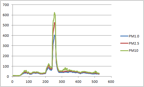
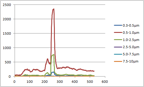
Given some of the issues and some further design changes that I wanted to include, I decided to re-spin the dust data logger design. But before moving on, here is a look at my existing dust data logger:
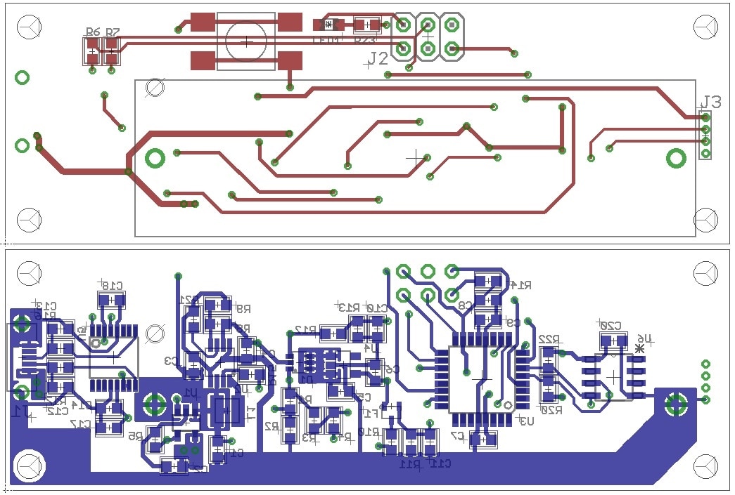
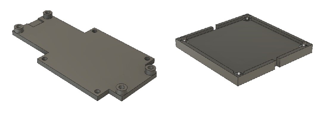
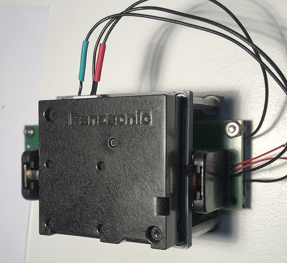
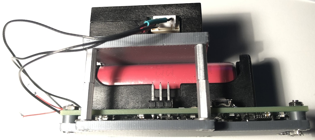
The Panasonic Smoke/Dust module snaps into place in the upper tray. I have also added small notches in the tray to allowing using cable ties to hold the sensor more securely in place (like when the units are placed into the A/C unit).
This prototype suffered some serious damage when during a debug/re-work cycle, I accidentally re-inserted the battery in the reversed direction and generated a fair amount of smoke (too bad the unit wasn't running so I could have collected some data on the smoke). The event took out both the charger and boost chips. After removal and replacement of the damaged chips, I discovered two more issues, first I had installed the wrong charger chip, explaining why the charge process was not working and second, that in the resoldering process, I had a bad solder joint, floating the voltage feedback circuit on the boost circuit. After yet another rework cycle, I was able to verify operation of both the battery charging and the 5 Volt boost operation.
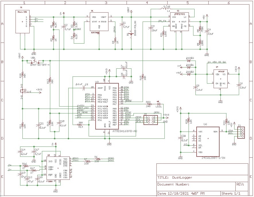
Moving forward into the new design, I had a couple of tweaks that I wanted to make on the design. Here is a short list of the changes:
- Enlarge pad size on the connector to the Smoke/Dust module.
- Add pads for zero ohm resistors to select communications (UART/I2C) and Power source for the Smoke/Dust modules (5 Volt Boost or USB power).
- Add a MOSFET power switch to isolate the charger from the USB power. This will allow me to try out some charging changes, like early termination of the charge process, i.e. no constant V phase.
- Replaced the single red/orange LED with an RGB LED to allow a wider range of indications.
- Swapped USB connector from bottom of the board to top of the board (easier testing and nice flat surface of the base of the module).
- Added inline PI filter (cap,ferrite,cap) to the 5 Volt power connection to the Dust/Smoke module to filter out high frequency noise.
Here are the revised schematic and layout:
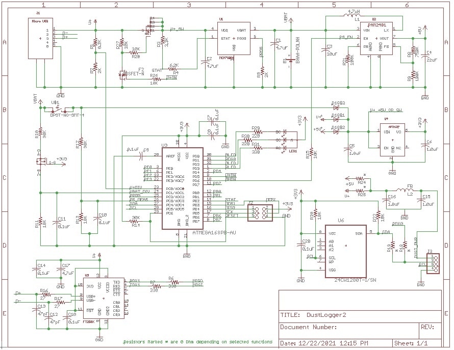

In thinking about the other test cases and other ways that I might use this sensor, it occurred to me that there is an easier approach to collecting the data. With the UART link working so nicely, I could simply use a USB to serial device to apply power to the sensor and to collect the data. Fortunately, I have a simple PCB design that I could use to do that.
Here are the schematics and layout for the module:
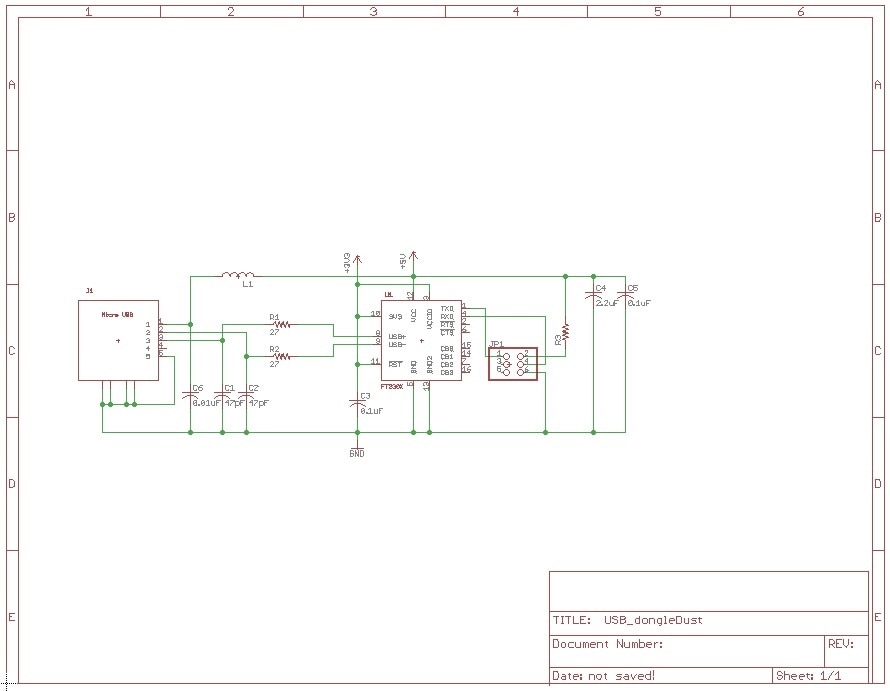
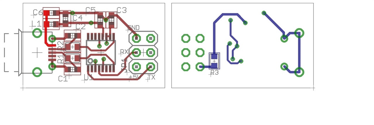
I originally designed this module to act as USB dongle that I could plug onto the ISP connector on a ATmega equipped board and access the UART port to interact with my DMX based boards. All I need for the Smoke/Dust sensor is to add a zero Ohm resistor to route the USB 5 Volt source to the sensor. Using my existing design PCBs (no R3 resistor), I was able to add a simple jumper wire to supply the necessary power. These tiny boards will be useful for testing in places where I have a computer nearby. I will need to write a simple control panel software to open multiple serial ports and log the data the sensor automatically send at a 1 sec rate.
I will continue to write updates to the roadtest project and then write a final post (as a review). In the meantime, I will continue write firmware and control panel software as I wait for my new PCBs to arrive.
Note: designing and building projects during the global parts shortages that we have been experiencing continues to be a challenge. Many of the parts I need are no longer available at most of the distributors that I normally use (including Avent). I have been forced in some instances to get parts through less reliable channels (like Ebay and Amazon), but in most cases, if you look hard enough and assume some risks, you can usually find what you are looking for (at much higher prices) .
Thanks for reading along!
Gene
