


This my final post before writing the review. I’ve struggled up to this point to deliver on the objectives in my application. Well I am happy to report I was successful with wrangling the SDR part of the Red Pitaya into what I promised, a radio receiver
When I first read the call notice for RoadTesters on this product, I recalled assembling a AM/FM radio receiver using RTL-SDR and GNU Radio. My goal was to attempt that same exercise using the Red Pitaya.
Before starting the exercise I needed a practice run. Some project that used Red Pitaya SDR capabilities that worked. This article from controlpath was an example I could use. An input a signal to Red Pitaya DSP engine and play it back on GNU Radio.
I don’t have a workshop with test equipment. My signal generator was 5kHz generated from a sox application running on a raspberry Pi, out the audio jack to IN1 input of the Red Pitaya. The Red Pitaya network connection would carry a signal to GNU Radio running on my Ubuntu computer.
What it would proved was that I could input a signal to Red Pitaya. I could output a signal to the network from the Red Pitaya. I could capture the network output on GNU Radio running on my computer.
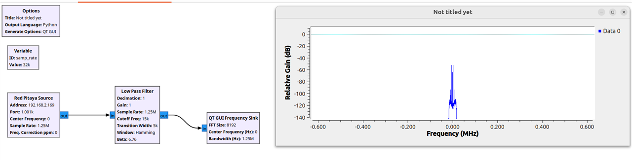
It worked! Those two words took close to six hours of effort to produce. I found nosie artifacts in output signals I couldn’t explain. In the end, I focused on the 5kHz signal. I varied the Pi output signal and GNU Radio sink output graph varied.
The Red Pitaya source block for GNU Radio came from Red Pitaya Notes . I could not nail down who exactly Pavel Demin was but it has a strong association with Red Pitaya development. Without that code there is no connection to Red Pitaya. The Rosetta stone was the links in this screen shot from the SDR transceiver startup screen.

The caveat was that my use case used different hardware or software versions. Warning in documents made it clear the code may not work. IP address the Red Pitaya source block correctly and GNU Radio makes the connection.
Getting a successful 5kHz test under my belt prompted me to shoot for the application objective. Build a radio receiver.
If I could replace the 5kHz signal with one from the AM radio band, could I build an AM radio receiver. The Red Pitaya documentation indicates analog input frequency range approximately 0–60 MHz. FM Radio wouldn’t make the frequency cut.
I confess this was a long shot. Pavel Demin’s Red Pitaya notes allude to the possibility. SDR Transceiver architecture, GNU Radio source/sink integration, and existing AM transceiver flowgraph (trx_am.grc). GNU Radio reference documentation for signal-processing blocks and their configuration offered some insight. My AI research assistant did the reading.
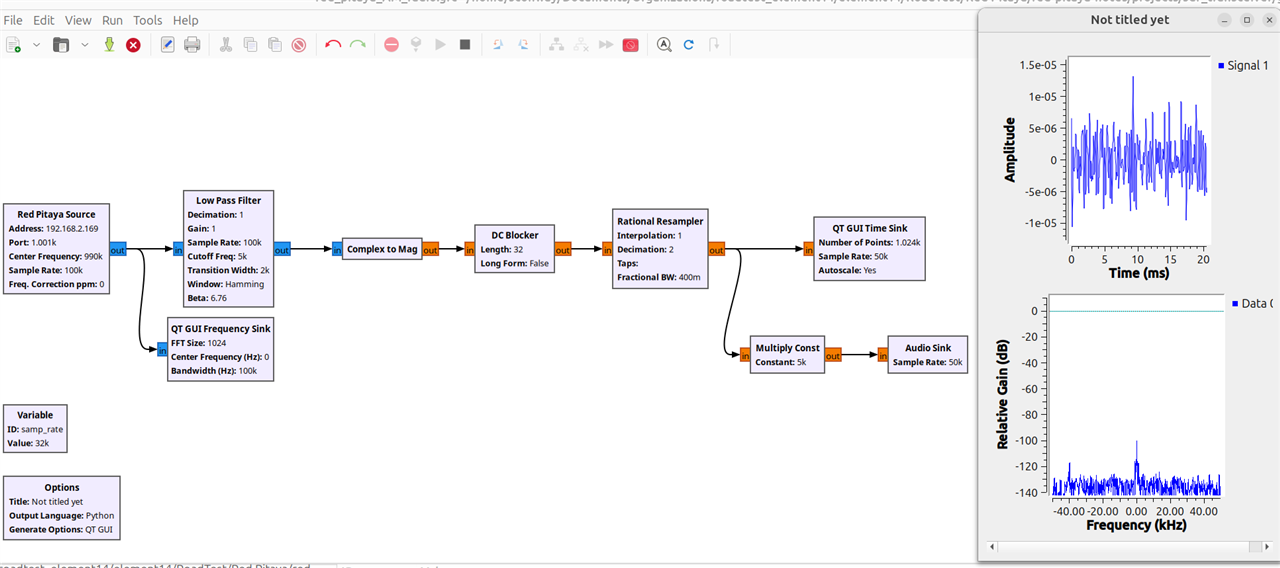
Before even starting I was skeptical. I didn’t have a proper AM receiver antenna. Antenna impedance didn’t match the Red Pitaya input. There is a balan available for purchase to handle the mismatch. I was already out money for the case, I was not going to purchase more. The last obstacle could I find a station that I could receive.
With a set of rabbit ear antenna connected to the input of the Red Pitaya I used the Spectrum Analyzer to scan the 500kHz to 1750kHz band looking for a signal. Once I found a signal, (the waterfall graph was most useful), I started assembling the parts.
Six hour later I was listening to a talk radio show at 990kHz. The voice audio was understandable. I cut my losses and didn’t spend time trying to clear up the static. The proof of concept was what I wanted.
I'm done kicking the tires and Red Pitaya STEMlab 125-14 PRO Gen 2 Starter Kit. My next post will be the review.