


I thought that I'd try out another of the basic overlays before moving on to a neural network application.
The PYNQ development software provides a set of logic tools using the logictools overlay. You can create a digital circuit by specifying its function and IOs with a simple, declarative API in Python.
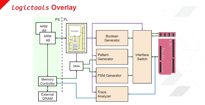
The logictools overlay has 3 function generators plus a trace analyzer to capture generated patterns.
- Boolean Generator - up to 26 independent Boolean functions of up to 5 inputs each can be specified simultaneously
- Pattern Generator - uses Wavedrom description language to specify arbitrary digital signals
- FSM Generator - specify a finite state machine with up to 8 inputs, 19 outputs (not simultaneously). e.g. FSM with up to 127 states, up to 6 inputs, and up to 14 outputs
- Trace Analyzer - captures signals and displays waveforms using the Wavedrom application
I'll go through an example of creating a waveform with Wavedrom and generating the pattern on a set of pins on the Arduino Uno compatible IO connectors.
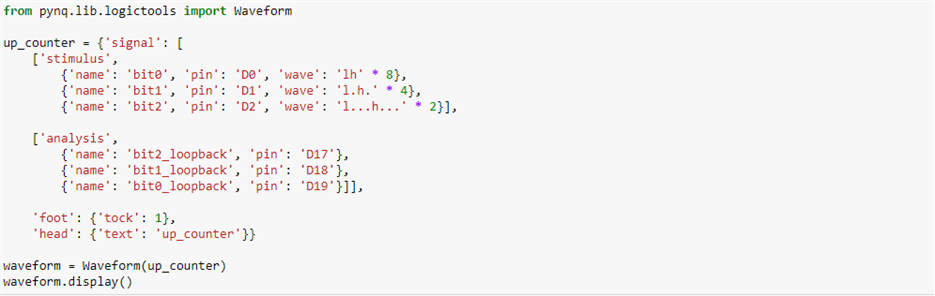
The Wavedrom application uses a straightforward JSON format to specify a waveform. Syntax is explained here: https://wavedrom.com/tutorial.html
For pattern generation the 3 primary keys are 'name' (signal name), 'pin' (hardware pin designator), and 'wave' (pin state at each clock).
Here is the 3 bit counter pattern that I'll be demonstrating:
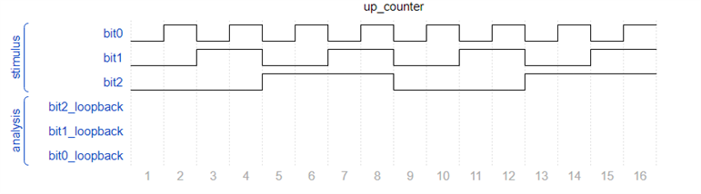
And the resulting pattern (the loopback waveform is not captured until the pattern and trace analyzer execute):
Short video showing the loopback operation and capture of the output waveform in the analyzer and an external scope:
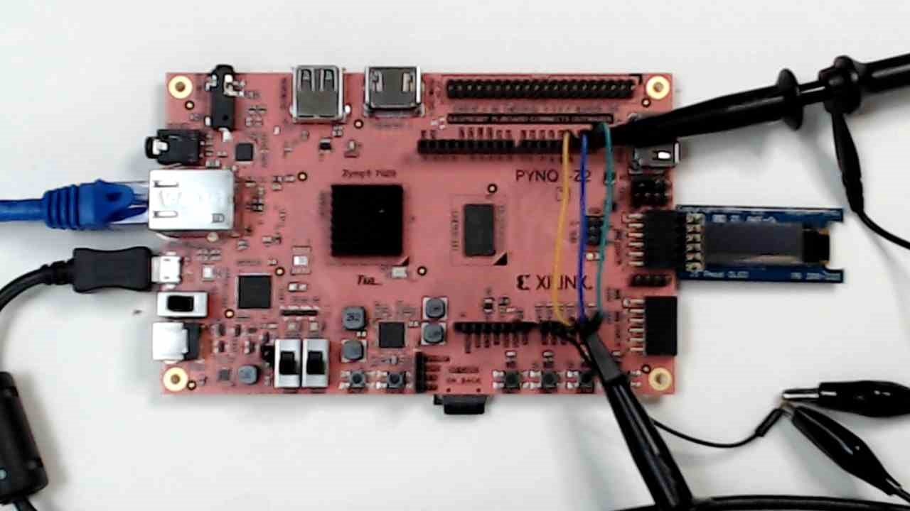
A picture of the physical setup:
Next for my roadtest I'm going to try some image processing with neural networks.
Top Comments