

MXO4 Logic Analyser
The MXO4 offers a logic analyser option. All the hardware is built in, but you need to pay for the Mixed Signal upgrade to get the probes and the software key to unlock it. That’ll add £2622 to the base price, so it’s not exactly cheap (although a good deal cheaper than Keysight’s equivalent add on the their Inifinvision 4 series scopes which is an extra £3500 or so.)
The first scope LA that I’ve owned was in an Agilent 54622D, which I bought some 22 years ago. It had a 16-channel analyser built in and no protocol decoders. But it was still pretty useful at the time because I had nothing better. It could sample digitally at 400Ms/s and it had 4M samples of memory.
The MXO4 has 16 channels, 400M samples of memory and a maximum sampling rate of 5Gs/s (although the pod bandwidth is only 400MHz) .
For testing the MXO4 I’m going to use my Efinix Dev Board (previously blogged about) and we’ll be looking at the interface between the FPGA and the two AP Memory APS6404memory chips. I wanted to connect the MXO4 directly to the memory chip pins but it proved to be too difficult to solder so many tiny wires to vias on the pcb, and I never got all of them working at once ! Because of this the MXO is connected to debug pins on the FPGA which does introduce some timing errors, but they won’t have any effect on these experiments.
PIC Efinx board with probes
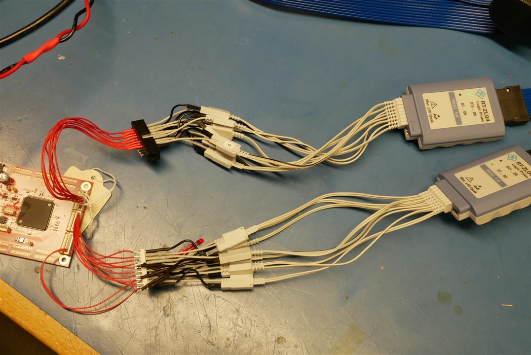
The MXO4 logic probes are the same as those supplied with the RTA4004. They come with hook probes and a lot of little leads. I haven’t used the hook probes.
Logic Analysers and scopes often have a lot of fancy trigger modes that can be difficult to set up. So the easy way is to trigger off pretty much anything and use the big memory to capture an all embracing dollop of data. This will reduce your setup time and gives confidence that you have captured all you intended. The downside is finding you way around the captured data.
Looking at a big blob of data
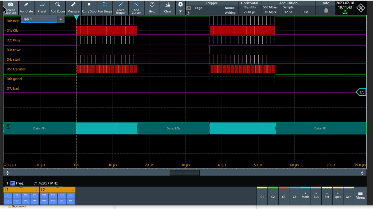
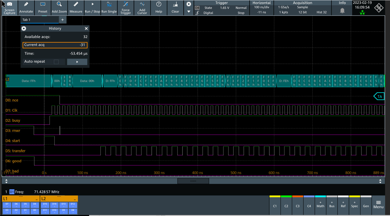
The capture was triggered on D4 which is the start signal for a memory transfer operation. It’s triggered by the internal test generator coded into the FPGA. I can start the test generator with a serial command to the processor on the Efinix FPGA board.
The test sequence writes 16 blocks of data to the memory chips and then reads them back, generating a total of 32 start pulses.
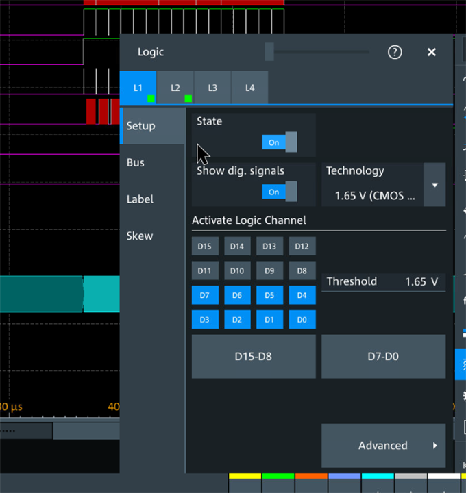
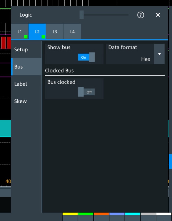
I set up the logic channels like this:
What I really want to do is look at the first block of data after a matching pair of write and then read bursts. All the data is there but it’s a problem getting at it.
On the Agilent 54622D (and on some other scopes) it was easy to use the horizontal position and scale controls to zoom into any place you liked. This just doesn’t work very well with the MXO4 (and with big data captures) because its very easy to get lost.
On the other hand you can use the Zoom function which allows you to select a window to zoom on the main display. It then splits the screen like this:
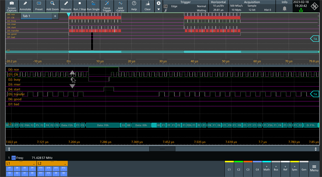
The high, low and edge levels of the digital signals are colour coded green, purple and white. It takes a little getting used to but on other scopes I've had trouble working out if I'm looking at high on the trace I mean or low on the next one up.
You can use the mouse scroll wheel to expand and contract the zoom (and you can move the zoom rectangle about or change zoom boundaries numerically). The zoom rectangle height as well as width changes.
The zoomed window doesn’t show timing.
But we can set cursors in the Zoom window:
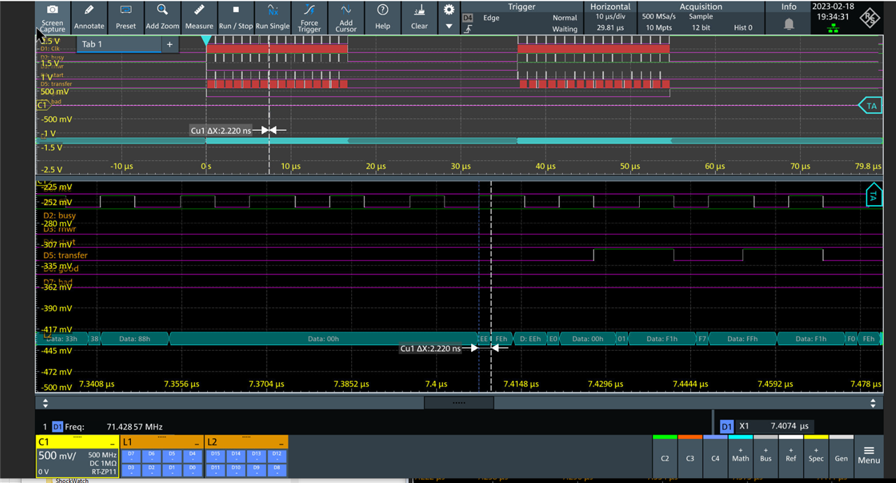
Here I’ve selected the width of a bad sample (where the sample time happened to coincide with a change of data on the bus).
I was puzzled by the displayed width – 2.220ns – the scope is sampling at 500Ms/s so the resolution is 2ns – how can a pulse be 2.220 ns long ?
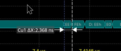
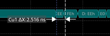
Two attempts at glitch width measurement exactly 1 cursor control knob click apart. 2.368ns and 2.516ns – so rather than the control moving 1 sample time per click it’s moving by 130ps per click which is 0.065 sample times. There really ought to be a way of locking the cursors to the sampling.
There aren’t any other tools for finding stuff in a blob of data. I’d rather hoped for a “goto next edge on channel x” at the very least.
Triggering in just the right place
As I said before, capturing a big chunk of data is easy to set up but difficult to sort out afterwards.
The MXO4 has fancy triggering options, so what we would like is to trigger on the nth "33 88" sequence on the bus, or maybe the first start, followed by n busy low to high transitions. Or even the 35th start.
Let’s have a look:
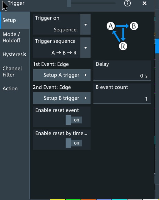
Choose sequence in the Trigger menu:
Then select some channels:
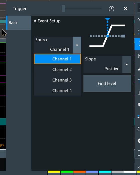
Woops ! No option to select digital channels in Trigger sequences.
What’s the point of a built in LA if its signals are second class ?
We could try hooking an analogue channel up but that's the sort of hard work we want avoid.
Maybe we could trigger off a pattern in the bus:
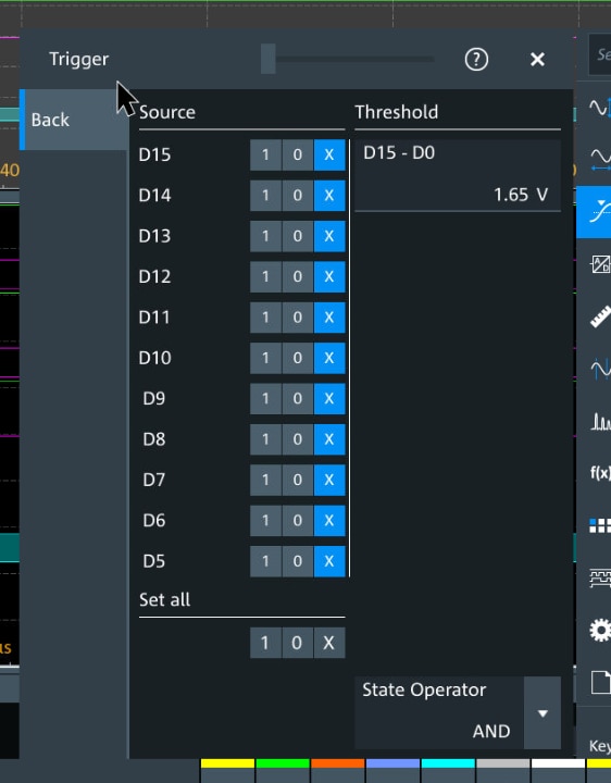
Well it looks possible, but doing it bit by bit is rather 1970s style (you know – those computers with switches and lights to set up the address and data bus.)
There doesn't seem to be a way to reference the bus in pattern or state setting.
Segmented memory
People talk about this a lot and the MXO4 claims special whizzy things for its segmented memory. Maybe that can save the day.
I copied this from the glossy leaflet:
And it says this:
Use segmented memory to capture signals separated by inactivity. Examples include laser pulses, serial bus activity and RF pulses. The segmented memory of the R&S®MXO 4 series oscilloscope enables signal capture over a long observation period up to 1 000 000 segments.
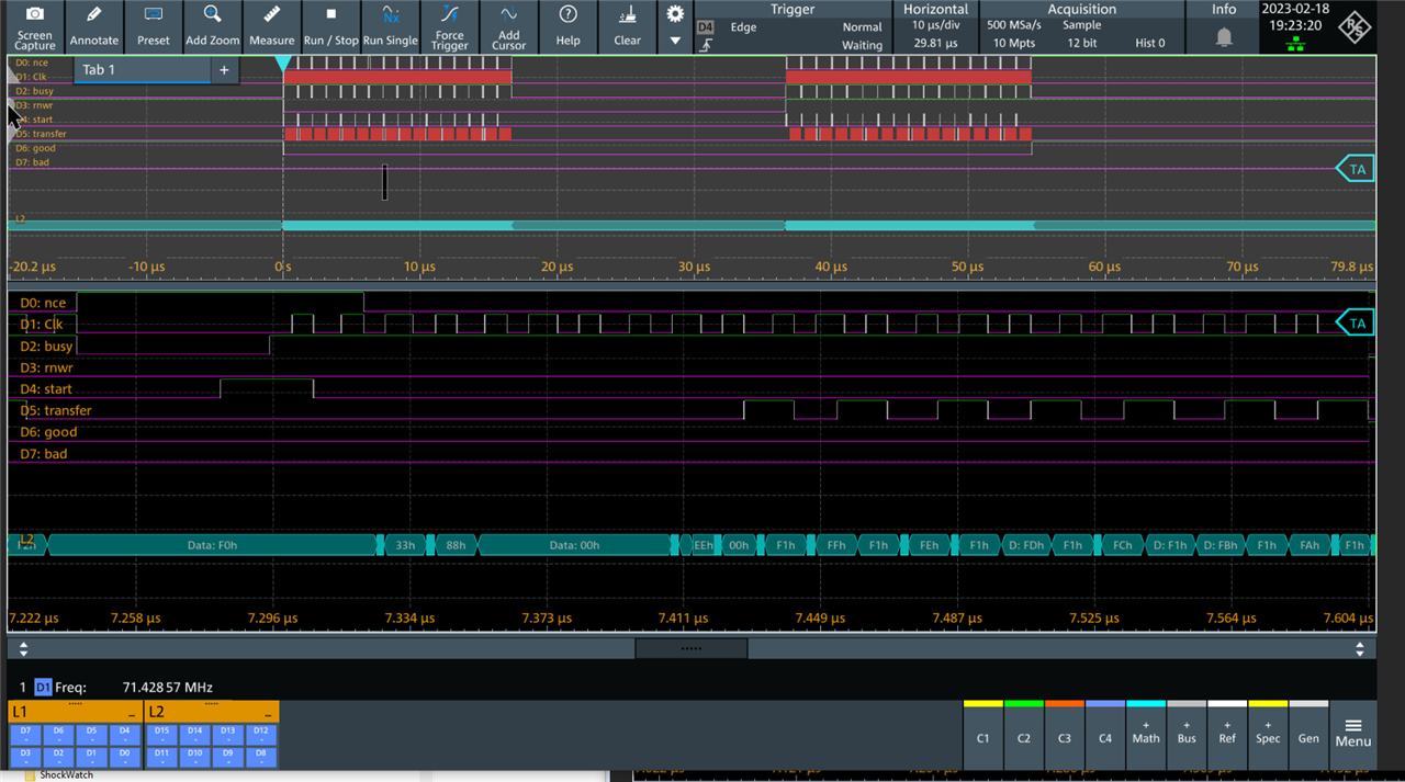
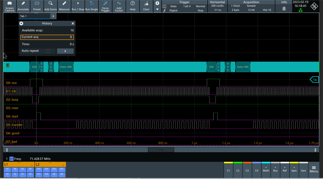
This trace is very nearly what we want:
It took a while to work out how to get there – but it looks almost right.
We have 32 captures in segments and we are able to select any one – so we can pick out any of the transfers for detailed looking.
I’ve altered the horizontal scale to show all the segment:
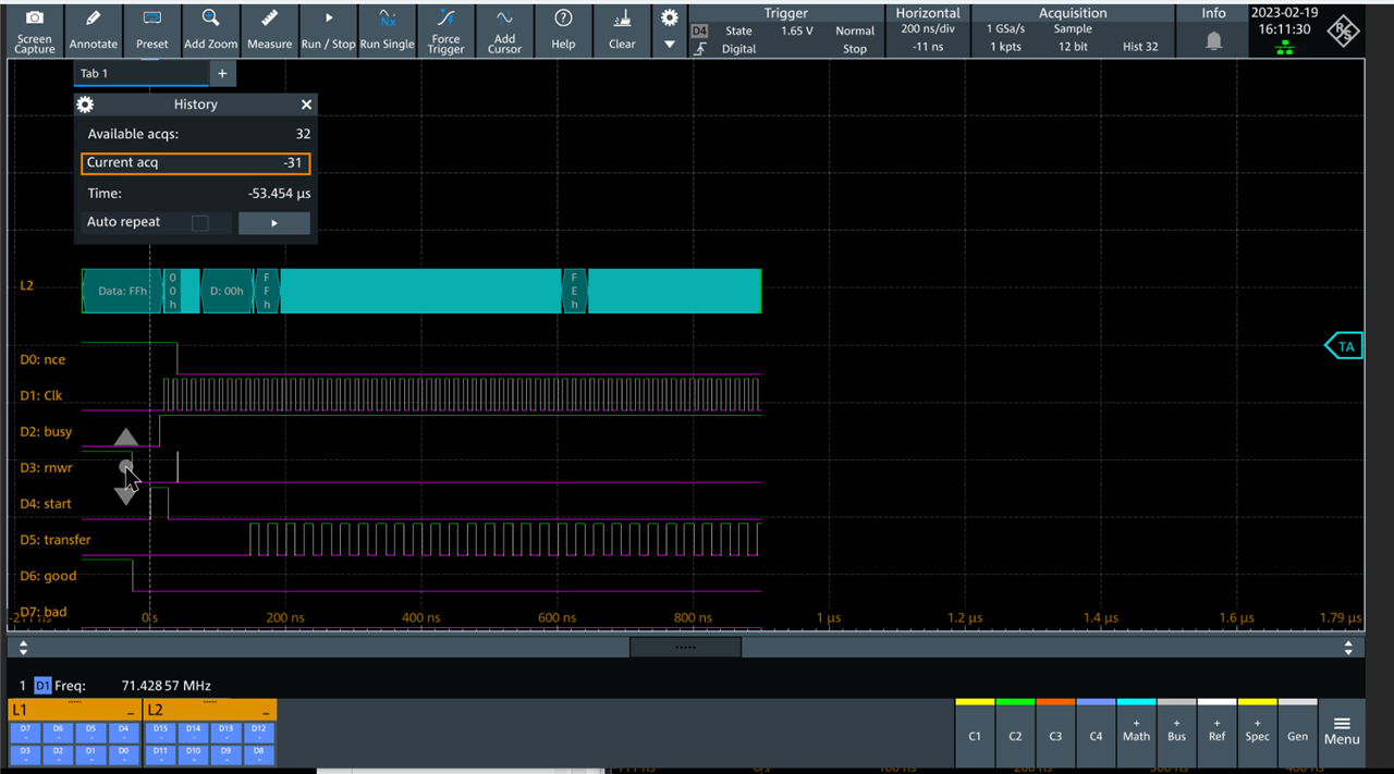
And the segment ends before the transfer did.
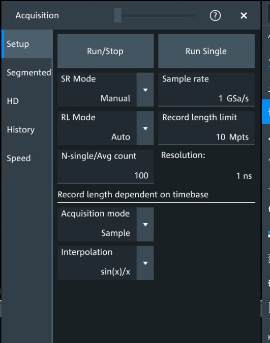
The settings will explain why:
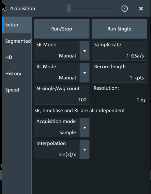
I’ve set the sample rate to control the time that the minimum number of samples I can set is shorter than the memory transfer packet time.
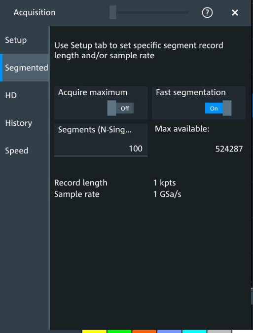
And here I’ve set fast segmentation to on.
But the problem is that I can only set the time duration of the segment to 1u or 2us, but the interval between start pulses (on D4) is about 1.2us.
OK – so let’s set the record length to automatic.
And then run and we get:
Scaled out to show complete capture.
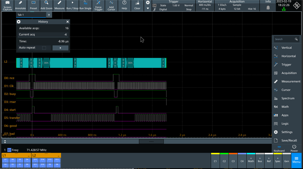
We only get 16 captures and some data is lost.
So that bit in the glossy where it says “Use segmented memory to capture signals separated by inactivity” really means signals that are separated by a load of stuff you don’t care about, because you can’t precisely set the end time of the segment.
If only the automatic setting on the record length had an option to stop the current segment and start the new one every time it saw the trigger condition ………..
Summary
I set out to do something that should be quite easy and is far from an unusual requirement. (Capture or examine single packets of data sent back to back at a modest rate (75MHz clock)).
The basic hardware has the ability to capture the data in big chunks, but lacks the tools to navigate it easily.
I think the segmented hardware could capture 1 packet per segment, but it doesn’t have the control options to make it possible.
If anyone has any ideas as to how else this problem might be approached I would be happy to try them.
The basic hardware core of the Logic Analyser is fine, its got a huge memory depth and can sample very fast. I didn't have any issues with glitches or crashes.
The big screen makes the feature a good bit more useable than some of my older scopes.

