
First of all, I want to thank element14 and Rohm for this great opportunity: testing the BD9G500EFJ-EVK-001 evaluation board and becoming for the first time a roadtester.
What's special about the BD9G500EFJ-EVK-001 ?
The BD9G500EFJ-EVK-001 is an evaluation board based on Rohm BD9G500EFJ-LA buck converter. This IC comes packed with many useful features:
- Enable/disable pin for optimized current consumption
- Large input voltage range
- Soft start
- Current mode control for fast transient response and easy feedback compensation
- Undervoltage lock out
- Thermal shut down
- Over voltage and over current protections
- Over voltage discharge
Last, but not least, it's advertised as "long time support product for industrial application". This alone can save some headaches to design engineers due to product end of life!
All these features make up for a DC/DC converter that seems to be a good fit for a large variety of applications. Starting from industrial applications and moving to e-bikes and e-scooters, RC cars, robotics, battery powered systems and many other applications the BD9G500EFJ-LA could prove itself to rule them all.
What's current mode operation and why is it useful?
I'm glad you asked! Looking at the literature we can find that "An ideal current-mode converter is only dependent on the dc or average inductor current. The inner current loop turns the inductor into a voltage controlled current source, effectively removing the inductor from the outer voltage control loop at dc and low frequency."
By removing the inductor at low frequency, we obtain a system that effectively has one less pole. We can then design with more ease the external voltage feedback loop without worrying too much about the second order output filter.
As we will see later, only one resistor and capacitor are needed for compensation!
Block diagram, directly from the datasheet. We can vaguely see the internal loop from SW pin back to "SLOPE" block inside the IC.The external feedback loop goes from output voltage back to FB pin. To tune loop stability is only needed a RC network connected to the "COMP" pin.
Unboxing and first impression
The kit arrived in a rather surprisingly large box. Other than the board itself, I received three IC samples. Very nice addition!
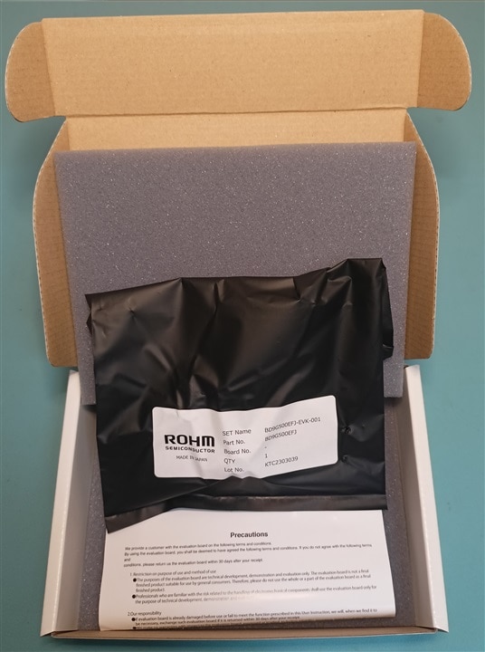
All was very nicely packed. The board was protected by a conductive bag and firmly kept inside the box by two foam pieces.
The board is a high quality 4 layer board with 70um copper on outside layers and 35um copper for inner layers. All components are nicely labelled on the front silkscreen but many of them are too tiny in my opinion (0402 package). Space is not a concern on this board and I would have preferred slightly bigger passives to ease up any component swap.
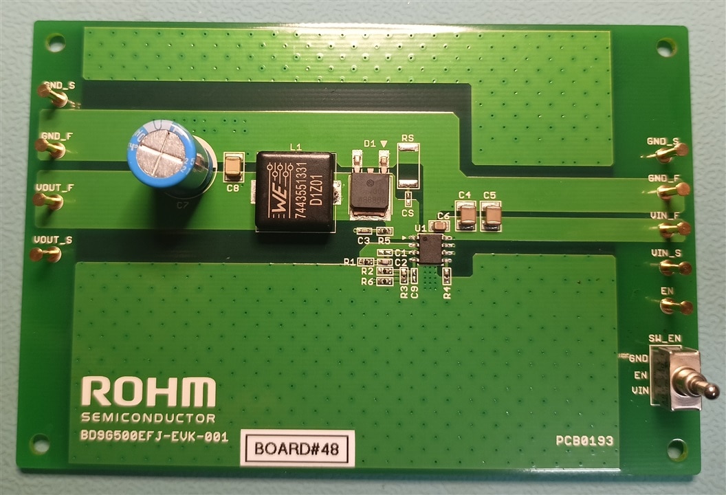
I like input and output test pins and the fact that are arranged for a 4-wire measurement, but there are not any other test points readily available to easily probe signals like switching node and feedback loop.
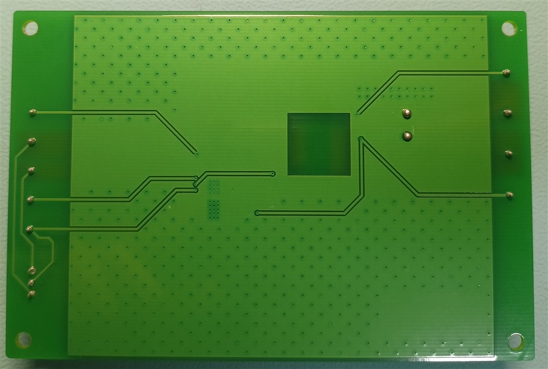
By flipping the board, we can see more clearly that ground planes don't extend all the way to board edges and leaves some traces "dangling" in mid air, without any reference plane. Moreover, there is a copper hole under the inductor that cuts all three ground layers. I don't know why they chose to do so (maybe there is a good reason that I don't know) but it's something that I would not suggest doing.
Documentation: a brief look
On the product page Rohm offers an extensive set of useful documents. For the context of this blog, I will keep it simple and I will focus strictly on the evaluation board user guide and the IC's datasheet.
The EVK user's guide is not too long and contains, other than the usual safety warnings, all the necessary information on the board coupled with some handy performance graphs. I'm going to take advantage of this user's guide later in this blog.
The datasheet seems well written and it has plenty of information about the IC as well as design guidelines and application examples. This seems a very good starting point for a design and I'm going to take full advantage of it later in my review.
It's worth noting that there are two possible part numbers for the same IC, but, as stated in the product page "We recommend BD9G500UEFJ-LA for your new development. It uses different production lines for the purpose of improving production efficiency. Electric characteristics noted in Datasheet does not differ between Production Line."
Testing the board: static performances
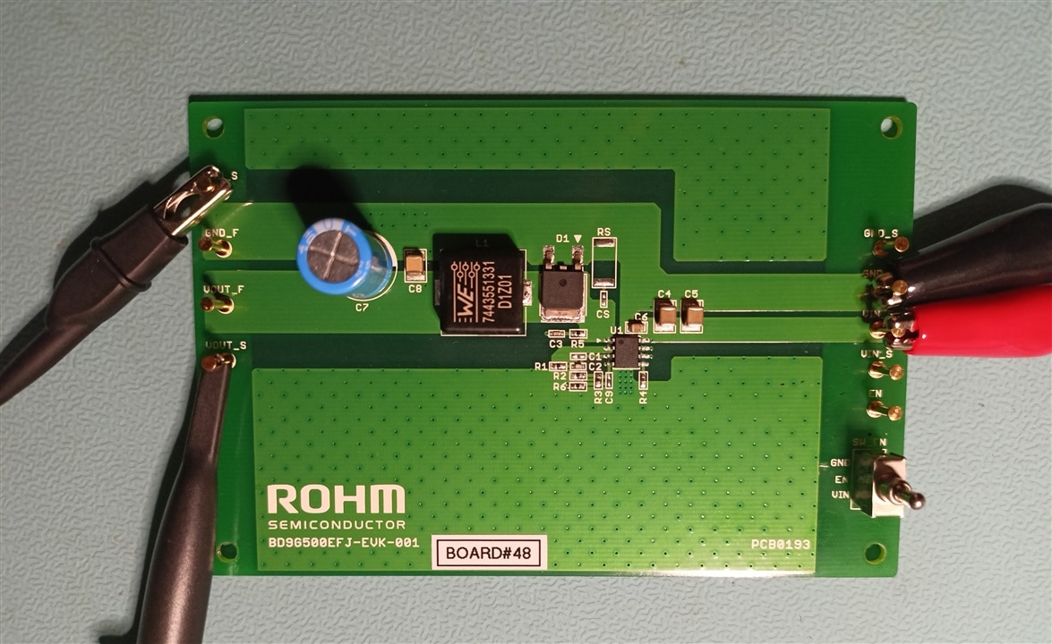
Following the EVK user guide, I connected the board to a power supply and a scope. I flicked the switch to "Vin" position and the board started working. Input and output pins are maybe a little bit close to be used with alligator clips, but they work a treat with scope probes.
One thing that caught my attention is the switch itself. It allow for three different positions: enable pin connected to Vin, to ground or floating. Usually leaving any high impedance pin floating is not a good idea, but in this case the BD9G500EFJ-LA has an internal pull down, keeping it in a stable condition.
Shutdown current
To measure shutdown current, the enable switch has been positioned to gnd. Input power is provided by my bench power supply (SPD3303C) and current consumption is measured with SDM3055 multimeter. This curve, as well as following ones, have been created by manually setting instruments and then plotting final results using Scilab.
Before each measure the circuit is left settling for a few seconds to avoid including in the data any transient effect.
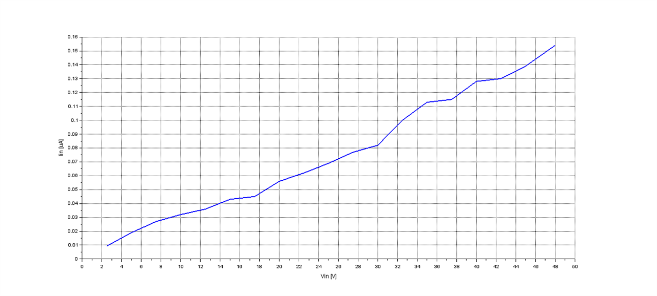 Input current consumption in shutdown mode.
With the circuit turned off, the current follows pretty linearly the input voltage, reaching about 150nA at 48V. This number alone is pretty good, but it's even more impressive if we take into account that we are not only measuring this IC current consumption but also any other possible leakage associated with the input circuitery of this board.
No load input current
Using the same setup as before, it's possible to measure the current consumption of this circuit without any load.
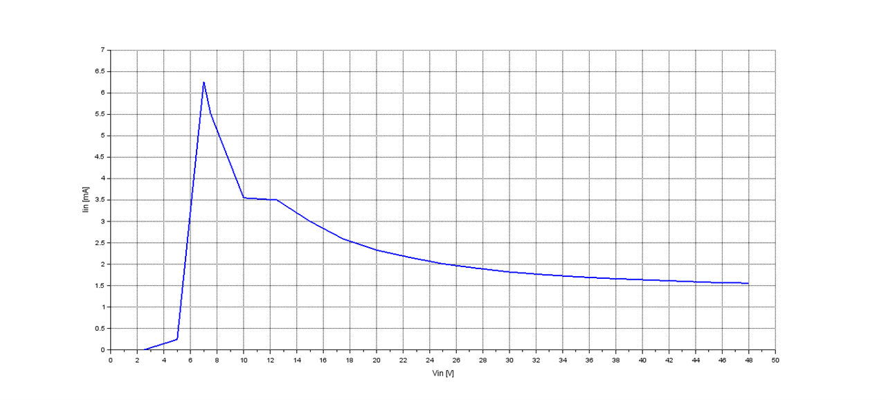
BD9G500EFJ-LA input current consumption
The current required to work has a peak around 7V and then tapers down as input voltage is increased, reaching about 1.6mA at 48V.
Line regulation
By connecting the supply directly to the board and by reading the output voltage, we can then verify the line regulation for the BD9G500EFJ-LA. Line regulation: almost independent from input voltage!
Except near the minimum input voltage, the output is independent from the input. Even from 7V to 7.5V I was able to measure a mere 1mV output change, which is insignificant.
All these graphs are coherent with data available in the board user guide. However, they provide little extra value. For this reason, I will give a "twist" to the next set of measures, looking at different characteristics from a slightly different angle.
Load regulation
The usual way to look at load regulation is to measure output voltage variation with respect to output load. This is already provided in the manual, but what if we would like to verify load regulation using a constant load, but changing input voltage? This scenario could well represent any battery powered application, where the load requires a stable amount of current (due to output voltage being more or less constant) but the input voltage could decrease due to battery discharging.
The measurement setup is the same as before, with the addition of a load. The output voltage is measured using "sense" test points, thus minimizing voltage variations due to output current.

Load regulation with 1.7A load and sweeping Vin
Here, the difference in output voltage between no load and about 1.7A load is depicted. Interestingly, we can see that in this particular case the load regulation gets better with higher input voltages and settles for input voltages over 30V.
Efficiency
Here I followed a similar approach and tested the efficiency with a constant load and changing input voltage. Output current and voltage are measured using two multimeters, one in series with the load for current and the other connected to output sense terminals. Input current and voltage are instead acquired directly from the power supply. This can slightly lower the overall measured efficiency due to losses in cables.
The load is a power resistor, drawing about 1.7A.
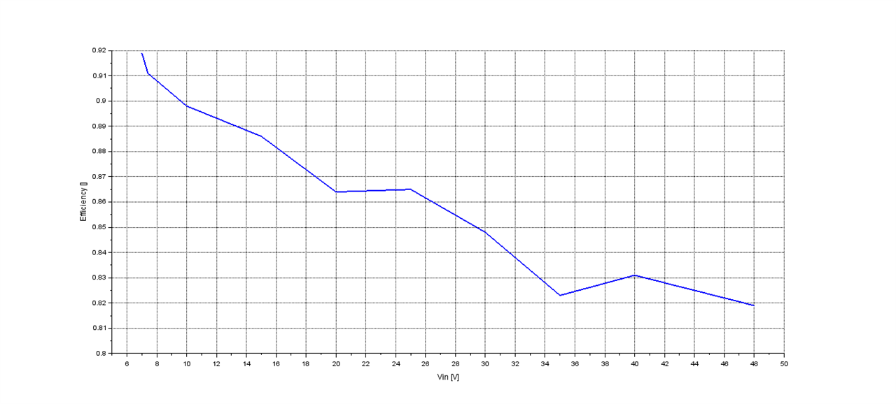
Efficiency with 1.7A load
Starting at 7V, we have the highest efficiency, almost 92%, and then it slowly decreases with increasing input voltage. It remains a respectable 82% at 48V, slightly higher compared to what is reported in the board manual (81% at 2.5A output current).
The curve is a bit wonky, but that's probably due to the limited resolution and accuracy of my power supply as well as a bit of noise in the measure itself.
Output ripple
More often than not, power integrity is taken for granted but it's an important topic for many different applications. For sensitive electronics, supply rail noise can have a significant effect on their performance. On switching converters, the first source of noise is the output ripple.
For this measure, input voltage is set to 24V and scope input is set to 20MHz bandwidth. The probe is set to x10 and not x1 because I wanted to keep the "standard" 20MHz bandwidth for these measures. Scope input is set to AC to cancel out the constant 5V output voltage.
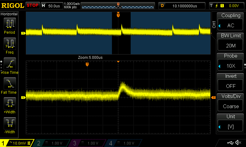 Output ripple with no load
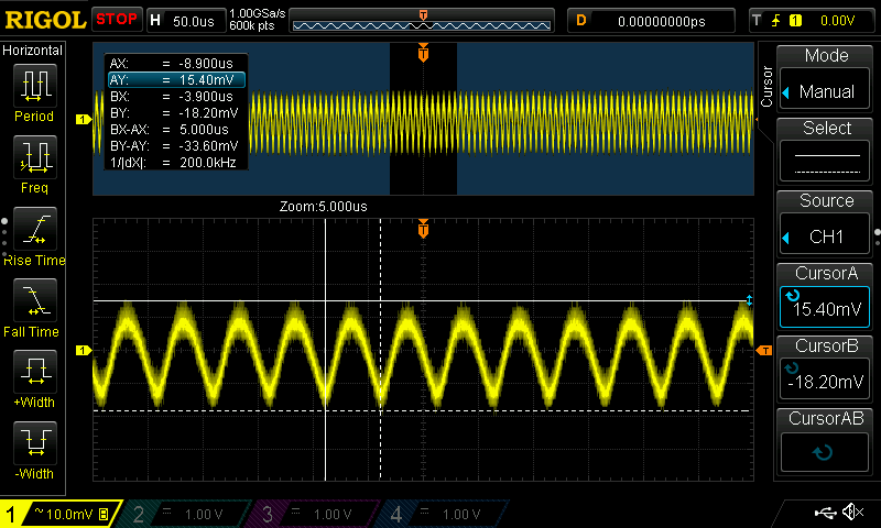 Output ripple with 1.7A load
Both loaded and unloaded, output ripple is very limited. Without any load, switching noise reaches 20mV peak and switching frequency is reduced. When loaded with 1.7A load, switching frequency goes up to the nominal 200kHz this particular board is set to. However, output ripple doesn't increase all that much, reaching about 35mV peak to peak.
Testing the board: dynamic performances and additional features
Input undervoltage lockout
The BD9G500EFJ-LA features input undervoltage protection: when input voltage falls under 6.4V, the converter shuts itself off, waiting for the input supply to rise over 7V before enabling once again the output. In case of undervoltage event, it cleanly turns off.
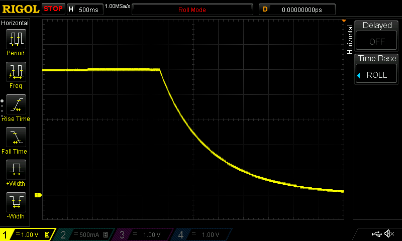 Output behavior during an input undervoltage event
Overcurrent/short circuit protection
Among all features, the BD9G500EFJ-LA also includes overcurrent and short circuit protection. To test this out, the bench power supply has been set to 24V and maximum allowable current to avoid any possible limitation on its side. on the output, I connected a scope probe on sense terminals and a current probe on a wire that will serve us as short.
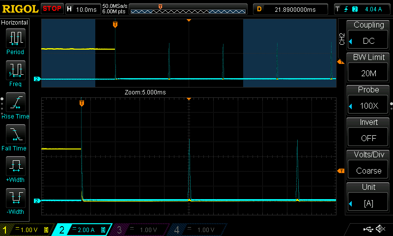 Short circuit protection in action. Yellow: output voltage; blue: output current
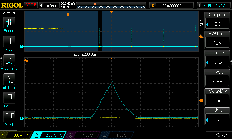 Close look to "hicchup pulse". Yellow: output voltage; blue: output current
Once the overcurrent threshold is reached (about 8A) the BD9G500EFJ-LA enters "hicchup mode" and tries to restart about every 20ms. When the overcurrent threshold is reached, it stops and waits another 20ms before trying again, until the fault is removed.
Soft start
This is a feature that I value a lot. Being able to turn on a supply rail in a controlled fashion is key to avoid ringing or unwanted circuit behavior during the start up phase.
I tested once again this feature without and with a 2.7Ohm load; input voltage set to 24V. This time I monitored the output voltage and input current.
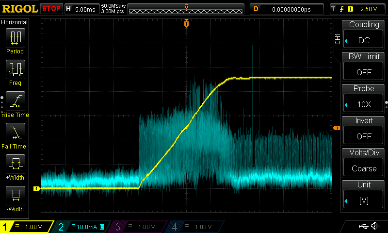 Soft start without any load. Yellow: output voltage; blue: input current
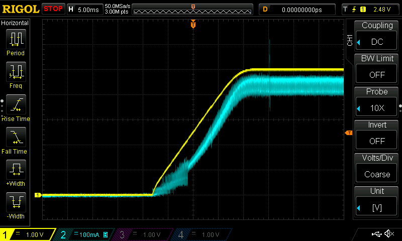 Soft start with resistive load. Yellow: output voltage; blue: input current
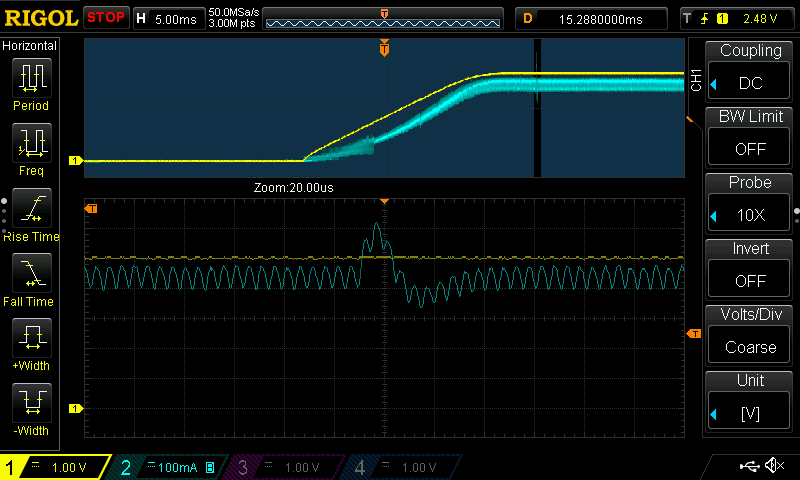 Small anomaly in input current after the start up sequence. Yellow: output voltage; blue: input current
The startup is very smooth and the input current is kept under control independently on loading. The output voltage rises linearly without any appreciable overshoot or ringing.
In both situations (but it's more clearly visible on the loaded test) after 20ms to 25ms from the initialization of the start up sequence, there is a small oscillation in the input current. I don't know what its root cause is(maybe a small discontinuity when the soft start procedure finishes?) but it's not something to worry about too much. Its magnitude and duration are extremely limited and output voltage is not affected at all.
Load step response
Last but not least, I'm going to try step response from 0A to 1.7A and see if the BD9G500EFJ-LA is up to what Rohm claims: fast transient response thanks to current mode architecture. Input voltage is once again set to 24V and I will acquire output voltage using sense pins and output current using a current probe.
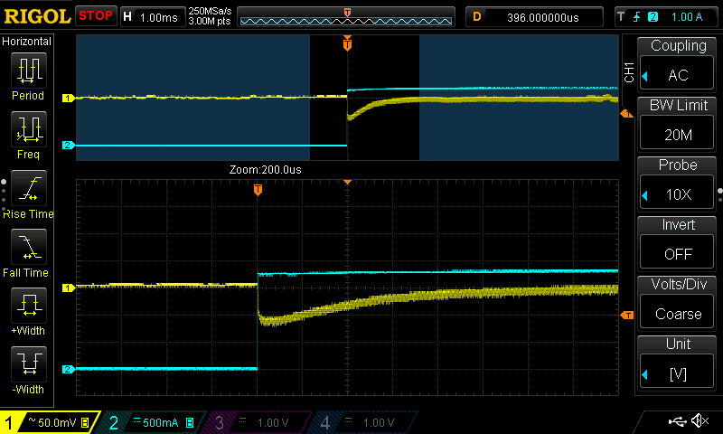 Load transient response. Yellow: output voltage; blue: output current
I think that this image speaks for itself. The load step has been perfectly handled, with a voltage dip limited to less than 70mV and a recovery time less than 1ms. Quite impressive.
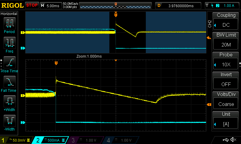 Load transient response. Yellow: output voltage; blue: output current
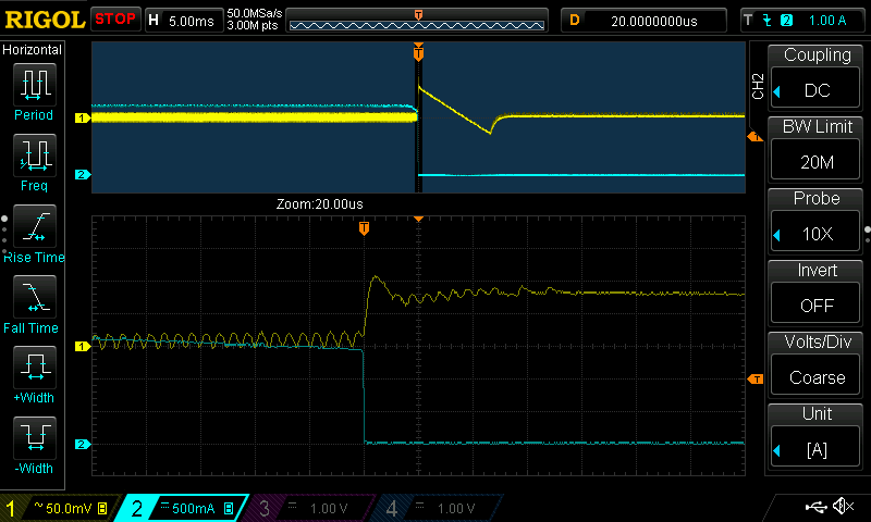 Load transient response, closer look. Yellow: output voltage; blue: output current
Going from 1.7A to 0A it's even harder to manage compared to 0A to 1.7A, but the BD9G500EFJ-LA handled it just fine. The overshoot this time is limited to 100mV. The transient to steady state this time is longer because there's nothing on the output that can lower the voltage, but looking closely, the IC response is still very fast and it completely stops switching after 100us, waiting for the output voltage to lower. This entire phase took about 7ms and caused a 50mV undershoot, then normal operation started again.
First verdict
In the end, this first roadtest blog ends up with a quite positive impression. Even if the board has some details that I don't like, such as the hole under the inductor or lack of test points for signals such as switching node, general performances were quite easy to measure and I took full advantage of the 4 wire set up available for input and output.
BD9G500EFJ-LA performances are very good. The incredibly low shutdown current makes it a good option for battery powered devices and the large input voltage swing makes it a flexible solution for many different applications.
There are many other good characteristics but for me the one that really shines is the incredible transient response that it provides under changing load conditions, keeping the output voltage very stable and with fast recovery time.
In the next part of this roadtest, I'm going to stress it a bit more and try to design a buck converter taking full advantage of documentation provided with the BD9G500EFJ-LA.
