


It was an exciting journey of learning for last 8 days or so, My first hands-on experience went smooth with MSP-EXP430FR4133MSP-EXP430FR4133 along with Code Composer Studio learning curve. Before we go to further details of what I was doing and did until now, I am going to explain a bit about MSP430FR4133 MCU itself.
Introduction to MSP430FR4133
The MSP430FR4133 is low power microcontroller with wide voltage supply range of 1.8V to 3.6V, It's a 16 bit RISC architecture with 16 MHz clock cycle, it has low power Ferroelectric Random Access Memory (FRAM) with the memory size upto 15.5KB, nonvolatile. MSP430FR4133 has special features like Intelligent Digital Peripherals with capability of IR Modulation logic which we can capture and store IR signals quick and accurate, low power LCD driver which supports 4x36 or 8x32 segment LCD configuration and on-chip temperature sensor.
MSP430FR4133 comes in Low profile Quad Flat Package (LQFP) with 64 pinouts. The pins are configured through bits and the available range is P1...P8 each series has 8 bits with number notation of Px.y, for example P1.0, P1.1, P1.2, P1.3, P1.4, P1.5, P1.6, P1.7. Each series count to 8 bits in total of 60 pins, yes it's not my bad maths instead, the P8 series has just 4 bits, P1 to P7 has 8 bits and P8 has 4 bits so in total of 60 pins, the rest of the 4 pins are VCC, GND, Reset and Clock. Total of 64 pinouts.
Almost all 60 I/O pins are able to configure as capacitive touch I/O, this is the most favourite feature of mine. I will spend another whole set of blog posts to experiment these capacitive touch I/O and libraries that Texas Instruments provides. But, for now let's finish this Roadtest...
MSP430FR4133 has 16 high-perfomance ADC channels in total, 10 external ADC channels to use via pinouts in P1.0, P1.1, P1.2, P1.3, P1.4, P1.5, P1.6, P1.7, P8.0, P8.1 as A0 to A9 respectively, 4 internal channels to select as on-chip temperature sensor, internal voltage reference(1.5V), VCC and GND. two channels are not used for no reason, don't know...
MSP430FR4133 has 16 interrupt pins on P1 and P2 pinout series to wake the microcontroller from Low Power Mode (LPM).
Supports three SPI, UART or I2C serial communications.
MSP-EXP430FR4133MSP-EXP430FR4133
MSP-EXP430FR4133MSP-EXP430FR4133 launchpad has on-board 8x32 LCD segment display which connected to MSP430FR4133 MCU, almost 39 pins connected to LCD with LCD driver pins.
20 GPIO pins are exposed to use in MSP-EXP430FR4133MSP-EXP430FR4133.
On-Board programer and debugger with eZ-FET which includes EnergyTrace technology feature, which TI's add-on plugin for Code Composer Studio to monitor power consumption reading in GUI.
Either eZ-FET to emulate on-board MCU or to be used as separate Emulator by isolating the eZ-FET by removing jumper block to program MSP430 family MCUs. eZ-FET supports almost all MSP430 family MCUs. my another favourite feature.
Code Composer Studio
My choice was CCS from the start as I am eager to learn professional embedded coding, The installation was bit long just because of my slow internet connection to download heavy size files and add-ons of CCS. It took me no time to program my first LED blink project as TI's CCS offer free examples on each MCU with bunch of example codes on every important features of MCU. installing drivers for programmer were went really smooth.
Trial Project
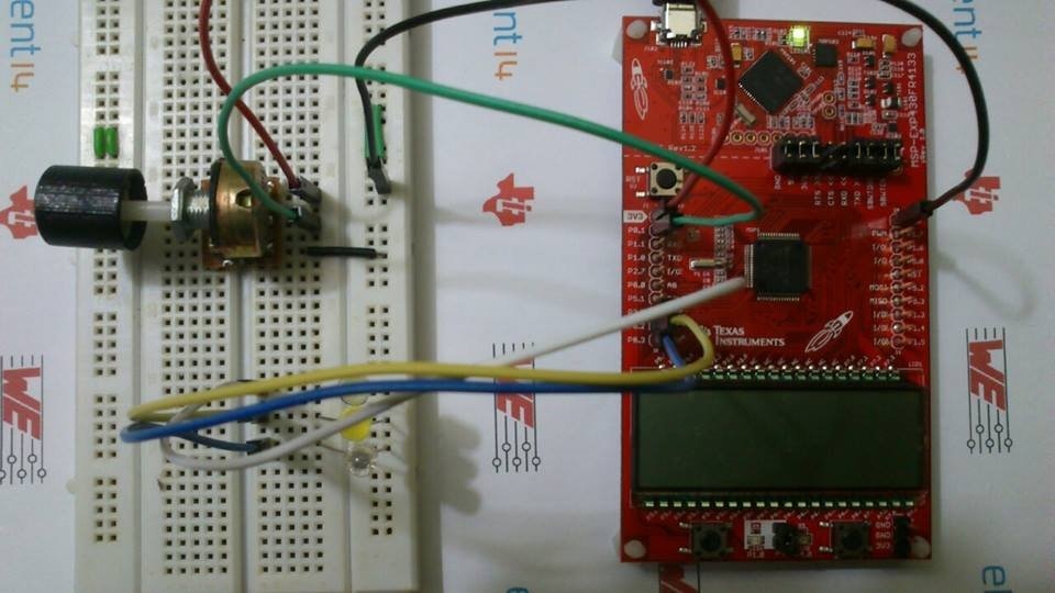
Before going to get started with my Roadtest idea I just wanted to test trial my idea with simple trial project which will be the miniature model of my big project, well for me it's BIG 
The idea is, using potentiometer to input various level of range voltage input to ADC channel and switch three LEDs accordingly on/off, which is exactly my Smart Vehicle Headlight idea.
My BAD maths of this project:
Potentiometer analog input = A (variable)
Voltage = V (3.3)
10 bit ADC resolution = R (1023 (0-1023))
The needed formula will be:
A×(V÷R)
Which will be:
A×(3.3÷1023)
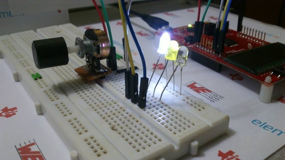
If the analog input range is from 750 to 1015 which will be assumed as nearly dark atmosphere, then turn on white LED.
This will be 2.41V to 3.27V input ADC voltage range to turn on white LED.
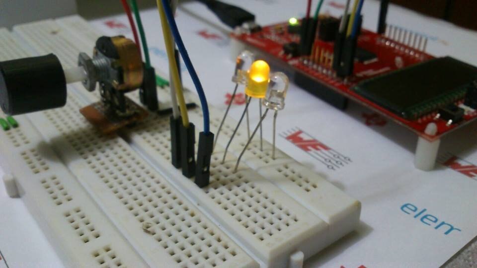
If the analog input range is from 500 to 700 which will be assumed as medium light source environment, then turn on yellow LED.
This will be 1.61V to 2.25V input ADC voltage range to turn on yellow LED.
If the analog input range is from 100 to 450 which will be assumed as enough light source situation, then turn on blue LED.
This will be 0.3V to 1.45V input ADC voltage to turn on blue LED.
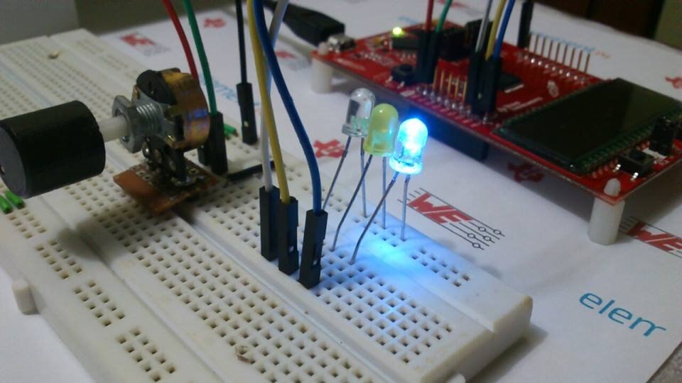
The trail project is successful as I am expected to be...
In Action...
The Code...
#include <msp430.h>

unsigned int ADC_Result;

int main(void)
{
    WDTCTL = WDTPW | WDTHOLD;                                // Stop WDT

    // Configure GPIO
    P2DIR |= BIT5;                                           // Set P2.5/LED to output direction
    P2OUT &= ~BIT5;                                          // P2.5 LED off

    P8DIR |= BIT2;                                           // Set P8.2/LED to output direction
    P8OUT &= ~BIT2;                                          // P8.2 LED off

    P8DIR |= BIT3;                                           // Set P8.3/LED to output direction
    P8OUT &= ~BIT3;                                          // P8.3 LED off

    // Configure ADC A9 pin
    SYSCFG2 |= ADCPCTL9;

    // Disable the GPIO power-on default high-impedance mode to activate
    // previously configured port settings
    PM5CTL0 &= ~LOCKLPM5;

    // Configure ADC10
    ADCCTL0 |= ADCSHT_2 | ADCON;                             // ADCON, S&H=16 ADC clks
    ADCCTL1 |= ADCSHP;                                       // ADCCLK = MODOSC; sampling timer
    ADCCTL2 |= ADCRES;                                       // 10-bit conversion results
    ADCMCTL0 |= ADCINCH_9;                                   // A9 ADC input select; Vref=AVCC
    ADCIE |= ADCIE0;                                         // Enable ADC conv complete interrupt

    while(1)
    {
        ADCCTL0 |= ADCENC | ADCSC;                           // Sampling and conversion start
        __bis_SR_register(LPM0_bits | GIE);                  // LPM0, ADC_ISR will force exit
        __no_operation();                                    // For debug only
        if (ADC_Result >= 0x2EE && ADC_Result <= 0x3F7){
            P2OUT |= BIT5;                                   // Set P2.5 LED on
        //P8OUT |= BIT2;                                   // Set P8.2 LED on
        //P8OUT |= BIT3; // Set P8.3 LED on
        }
        else{
            P2OUT &= ~BIT5;                                  // Clear P2.5 LED off
        //P8OUT &= ~BIT2;                                  // Clear P8.2 LED off
        //P8OUT &= ~BIT3; // Clear P8.3 LED off
        }

        if (ADC_Result >= 0x1F4 && ADC_Result <= 0x2BC){
            //P2OUT |= BIT5;                                   // Set P2.5 LED on
        P8OUT |= BIT2;                                   // Set P8.2 LED on
        //P8OUT |= BIT3; // Set P8.3 LED on
        }
        else{
            //P2OUT &= ~BIT5;                                  // Clear P2.5 LED off
        P8OUT &= ~BIT2;                                  // Clear P8.2 LED off
        //P8OUT &= ~BIT3; // Clear P8.3 LED off
        }

        if (ADC_Result >= 0x64 && ADC_Result <= 0x1C2){
            //P2OUT |= BIT5;                                   // Set P2.5 LED on
        //P8OUT |= BIT2;                                   // Set P8.2 LED on
        P8OUT |= BIT3;  // Set P8.3 LED on
        }
        else{
            //P2OUT &= ~BIT5;                                  // Clear P2.5 LED off
        //P8OUT &= ~BIT2;                                  // Clear P8.2 LED off
        P8OUT &= ~BIT3;  // Clear P8.3 LED off
        }
        __delay_cycles(5000);
    }
}

// ADC interrupt service routine
#if defined(__TI_COMPILER_VERSION__) || defined(__IAR_SYSTEMS_ICC__)
#pragma vector=ADC_VECTOR
__interrupt void ADC_ISR(void)
#elif defined(__GNUC__)
void __attribute__ ((interrupt(ADC_VECTOR))) ADC_ISR (void)
#else
#error Compiler not supported!
#endif
{
    switch(__even_in_range(ADCIV,ADCIV_ADCIFG))
    {
        case ADCIV_NONE:
            break;
        case ADCIV_ADCOVIFG:
            break;
        case ADCIV_ADCTOVIFG:
            break;
        case ADCIV_ADCHIIFG:
            break;
        case ADCIV_ADCLOIFG:
            break;
        case ADCIV_ADCINIFG:
            break;
        case ADCIV_ADCIFG:
            ADC_Result = ADCMEM0;
            __bic_SR_register_on_exit(LPM0_bits);            // Clear CPUOFF bit from LPM0
            break;
        default:
            break;
    }
}
So far so good...I am experimenting the LEDs that I have received from Würth Elektronik to move on further about this project...I will update more review of CC2540TDK-LIGHTCC2540TDK-LIGHT and TPS92512EVM-001TPS92512EVM-001 with my project updates.
Top Comments