


The real excitement is started and I am really excited about this, yes I have started creating my project and it's in progress. I just wanted to do a beta version of my project before go for main stream, the result was pretty amazing, exactly what I expected to do. My original idea was to use LEDs as ambient sensors, well, it's the thing that hold me to post my blog post for a week, the LEDs not picking up the light accurately, I am getting fluctuation of voltage input in mV which is bad to ADC sampling and I can't get accurate ADC data to process, so, I have decided to flip my sensor usage to LDR (Light Dependent Resistor) from my original idea, surprisingly the result is great.
Twist in the Plot
This time I am using CCS cloud as it was an accident that put me in a situation which forced me to search for an alternative IDE, I was ended up in CCS cloud and it's not that bad, to be honest it will help to get things done without sacrificing much. Just keep your development size to small, for dedicated large development CCS desktop app is perfect fit. Ah! well, the accident i am mentioning was literally an accident, my desktop SMPS burned in front my eyes...I had to replace it... now it's working fine.
Beta - Wagon
So, the idea is simple to use LDR as ambient sensor to drive my Smart Headlight, I am using 100k resistor with LDR to create voltage divider circuit which is giving data sampling to ADC channel with 3.3v on-board voltage reference. The LDR resistance changes according to the light source and it gives sampling data to A8 ADC channel.
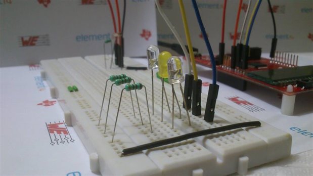
As well, I am using the raw ADC data for processing as it will give much room to calculate data than converting into voltage. if the ADC result is less than 100 which is low LDR resistance, it triggers blue LED, if the ADC result is greater than 150 and less than 400 which is medium LDR resistance, it triggers yellow LED, if the ADC result is greater than 450 which is high LDR resistance, it triggers white LED.
The three LEDs white, yellow and blue are connected to P2.5, P8.2 and P8.3 respectively which is configured as output GPIO pins. The coding is in C...
#include <msp430.h>


unsigned int ADC_Result;
int Volt_ADC;
int Volt_Result;


int main(void)
{
    WDTCTL = WDTPW | WDTHOLD;                                // Stop WDT


    // Configure GPIO
    P2DIR |= BIT5;                                          // Set P2.5/LED to output direction
    P2OUT &= ~BIT5;                                          // P2.5 LED off

    P8DIR |= BIT2;                                          // Set P8.2/LED to output direction
    P8OUT &= ~BIT2;                                          // P8.2 LED off

    P8DIR |= BIT3;                                          // Set P8.3/LED to output direction
    P8OUT &= ~BIT3;                                          // P8.3 LED off

    // Configure ADC A8 pin
    SYSCFG2 |= ADCPCTL8;


    // Disable the GPIO power-on default high-impedance mode to activate
    // previously configured port settings
    PM5CTL0 &= ~LOCKLPM5;


    // Configure ADC10
    ADCCTL0 |= ADCSHT_2 | ADCON;                            // ADCON, S&H=16 ADC clks
    ADCCTL1 |= ADCSHP;                                      // ADCCLK = MODOSC; sampling timer
    ADCCTL2 |= ADCRES;                                      // 10-bit conversion results
    ADCMCTL0 |= ADCINCH_8;                                  // A8 ADC input select; Vref=AVCC
    ADCIE |= ADCIE0;                                        // Enable ADC conv complete interrupt

    while(1)
    {
        ADCCTL0 |= ADCENC | ADCSC;                          // Sampling and conversion start
        __bis_SR_register(LPM0_bits | GIE);                  // LPM0, ADC_ISR will force exit
        __no_operation();                                    // For debug only

        Volt_ADC = ADC_Result * (3.3/1023);
        Volt_Result = Volt_ADC/11;

        if (ADC_Result > 450) {
            P2OUT |= BIT5;
            P8OUT &= ~BIT2;
            P8OUT &= ~BIT3;
        }
        else if (ADC_Result > 150 && ADC_Result < 400) {
            P2OUT &= ~BIT5;
            P8OUT |= BIT2;
            P8OUT &= ~BIT3;
        }
        else if (ADC_Result < 100) {
            P2OUT &= ~BIT5;
            P8OUT &= ~BIT2;
            P8OUT |= BIT3;
        }
        __delay_cycles(2000);
    }
}


// ADC interrupt service routine
#if defined(__TI_COMPILER_VERSION__) || defined(__IAR_SYSTEMS_ICC__)
#pragma vector=ADC_VECTOR
__interrupt void ADC_ISR(void)
#elif defined(__GNUC__)
void __attribute__ ((interrupt(ADC_VECTOR))) ADC_ISR (void)
#else
#error Compiler not supported!
#endif
{
    switch(__even_in_range(ADCIV,ADCIV_ADCIFG))
    {
        case ADCIV_NONE:
            break;
        case ADCIV_ADCOVIFG:
            break;
        case ADCIV_ADCTOVIFG:
            break;
        case ADCIV_ADCHIIFG:
            break;
        case ADCIV_ADCLOIFG:
            break;
        case ADCIV_ADCINIFG:
            break;
        case ADCIV_ADCIFG:
            ADC_Result = ADCMEM0;
            __bic_SR_register_on_exit(LPM0_bits);            // Clear CPUOFF bit from LPM0
            break;
        default:
            break;
    }
}
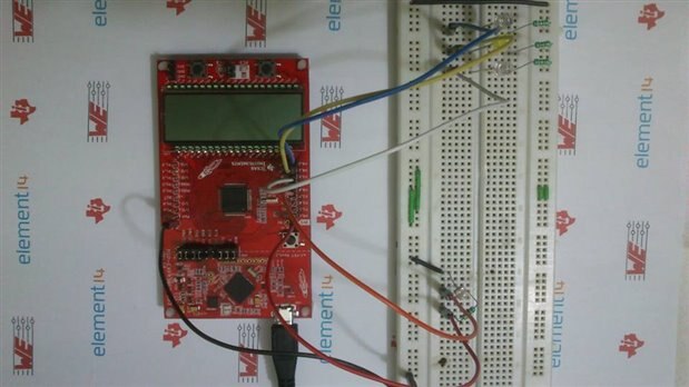
Visual Proof
It was a successful beta version my next step is to prepare SMD LEDs and circuit board to create Headlight setup. I am on it...in next coming blogs I will show the process of making the Headlight circuit board.
Top Comments