


Top Hardware Features Evaluation
This blog is in continuation from the Rohde & Schwarz Oscilloscope Kit RTM3K-COM4 - Review
Setup the Oscilloscope for Measurements
Fig: Setup the oscilloscope for measurements
Experimenting with the SPI Protocol
SPI or serial peripheral interface is a four wire bus which is used in synchronous serial communication. The interface is popular with many sensors and was originally developed by Motorola in 1980s.

Fig: SPI communication
In this experiment to test the SPI protocol; I used a Raspberry Pi as the SPI master talking to an Adruino as the slave SPI.


Fig: Test Setup for the SPI Protocol
Measurement Results for SPI protocol. A data stream is sent continously from raspberry pi to the Adruino Uno board.
uint8_t tx[] = {
       0x55, 0xAA, 0x55, 0xAA, 0x55,
       0xAA,
       0x55, 0xAA, 0x55, 0xAA, 0x55,
       0x0A
};

Fig: Measurement Result as seen in RTM 3004
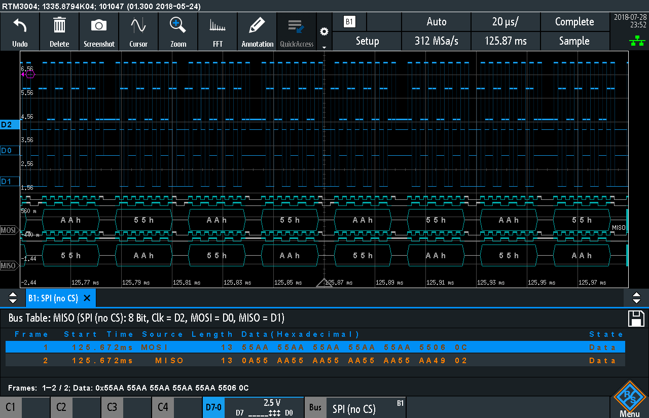
Fig: Result of the SPI Protocol
Testing the UART Protocol
A simple set up using the MBED board was used to measure the UART RX and TX as shown below.
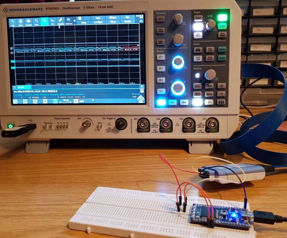
Fig: Test Setup
Fig: Setting up and Measuring the UART TX and RX
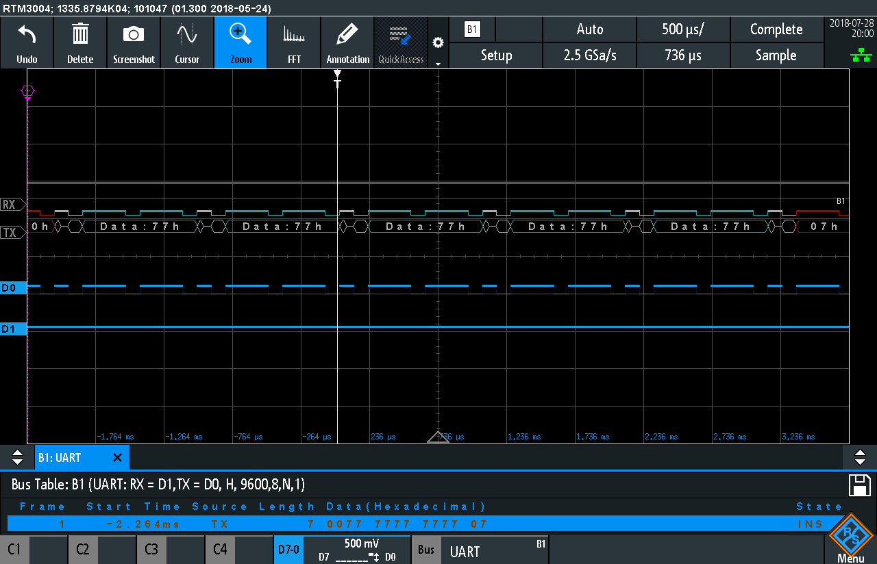
Fig: UART Measurement Result
I2C Protocol Measurements
Using the same setup as above I2C protocol was activated and measured as shown below.
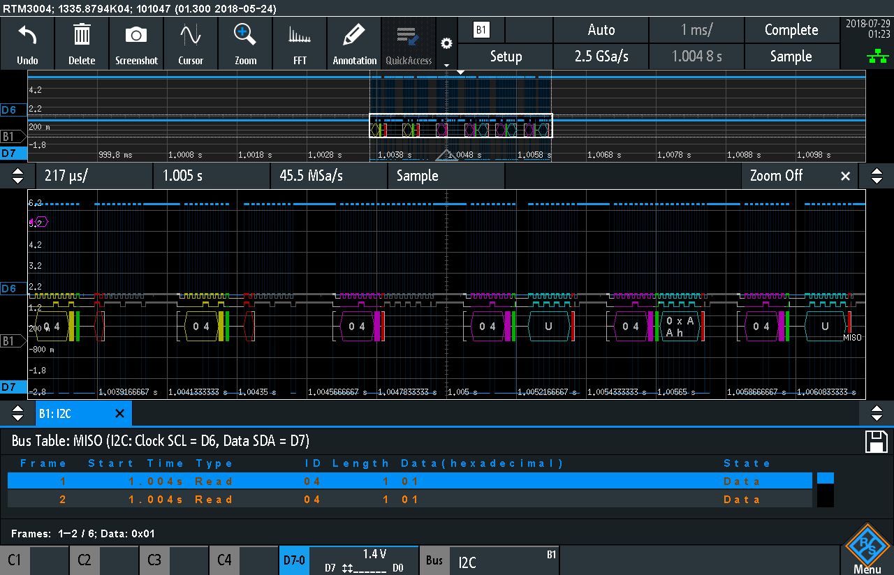
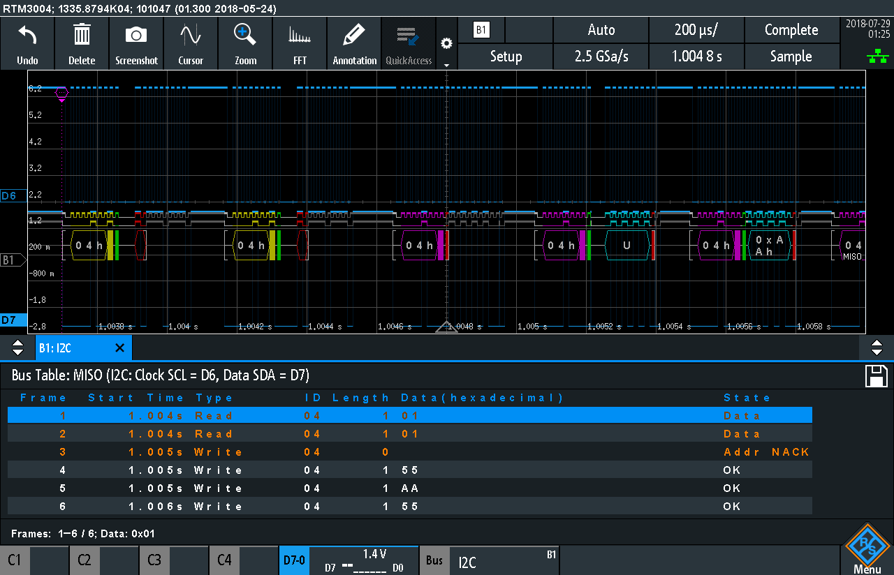
Fig: I2C Protocol Measurement Results
Conclusion
Clearly the RTM 3004 offers many digital bus decoding protocols; some of which have been presented here. This scope acts as powerful tool for digital designer engineers.
Top Comments