The PIC32 Ethernet Starter Kit is the 3rd version of a series of PIC32 starter kits. This is not my first time for working with Ethernet enabled microcontrollers but a first for PIC32 family.
Package Content
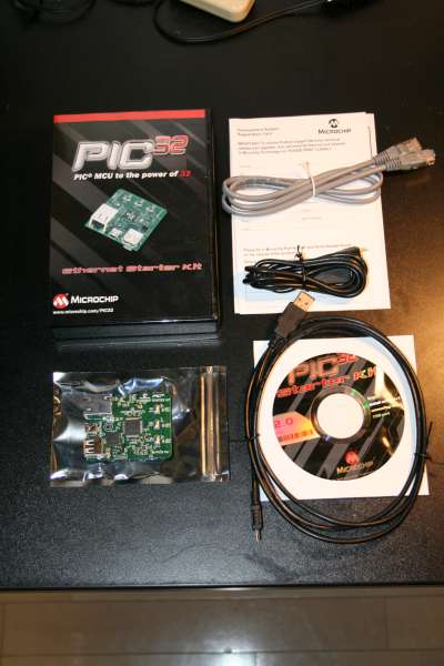
The kit came in a black plastic box which resembles a DVD box. The contents were:
- PIC32 Ethernet Starter Kit development board
- USB Mini-B to full-sized A cable – USB debug cable to debug and power the board
- USB Micro-B to full-sized A cable – PIC32 USB cable to communicate with the PIC32 USB port
- RJ-45 CAT5 Ethernet patch cable – Ethernet CAT5 cable to communicate with the PIC32 Ethernet port
- Software CD
- Registration card
Hardware
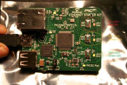
The PIC32 Ethernet Starter Kit board has the same form factor and expansion connector as the previous starter kits. It contains PIC32MX795F512L as the main microcontroller, a PIC32MX440F512H as the on-board debugger, a National DP83848 PHY for ethernet connection, a 120-pin Hirose connector for expansions and three LEDs (green, orange and red) & three pushbuttons for user interaction.
The board also has a USB Mini-B for debugger connection, a USB Micro-A/B for USB peripheral and OTG applications, a USB full-sized A for USB host applications and a RJ-45 jack for Ethernet connection.
The board also has some unpopulated parts such as Y3, C15, C16 for RTCC; R24 and R27 for USB-OTG voltage converter and C19-C24 decoupling capacitors.
The microcontroller has the following specifications:
- MCU Core: 80MHz, 1.56 DMIPS/MHz, 32-bit MIPS M4K
Core USB 2.0 On-The-Go peripheral with integrated PHY 10/100 Ethernet MAC with MII/RMII Interfaces; 2 x CAN2.0b modules with 1024 buffers; 8 dedicated DMA Channels for USB OTG, Ethernet, and CAN; 5 stage pipeline, Harvard architecture; MIPS16e mode for up to 40% smaller code size; single cycle multiply and hardware divide unit; 32 x 32-bit core registers; 32 x 32-bit shadow registers; and fast context switch & interrupt response.
- MCU System Features: 512K flash (plus 12K boot flash); 128K RAM (can execute from RAM;) 8 channel general hardware DMA controller flash; pre-fetch module with 256 byte cache; lock instructions or data in cache for fast access; and programmable vector interrupt controller.
- Analog Features: Fast and accurate 16 channel 10-bit ADC, max 1 mega sample per second at +/- 1LSB, and conversion available during SLEEP & IDLE.
- Power Management Modes: RUN, IDLE, and SLEEP modes; multiple switchable clock modes for each power mode, enables optimum power settings.
- Debug Features: iFlow Trace: Non-intrusive Hardware Instruction Trace port (5 Wires); 8 hardware breakpoints (6 Instruction and 2 Data); 2 wire programming and debugging interface; and JTAG interface supporting Programming, Debugging and Boundary scan.
- Other MCU Features: Fail-Safe Clock Monitor – allows safe shutdown if clock fails; 2 internal oscillators (8MHz & 31KHz); hardware RTCC (Real-Time Clock and Calendar with Alarms); watchdog timer with separate RC oscillator; pin compatible with 16-bit PIC MCUs; and serial communication modules allow flexible UART/SPI/I2C
configuration.
Software Installation
The software CD in the kit is a bit outdated, but I installed it anyway for the drivers. However, this caused problems with MPLAB IDE I have (8.50), I couldn’t open the latest version installed on my system and the version that was installed by the CD kept crashing each time I tried to connect to the board. So I zipped the starter kit folder, uninstalled it and unzipped so that I can use the demo files and other documentation in these folders.
Driver for the Debugger
The installation manual gives the general idea about how to install the device drivers. If you have a full installation of the latest MPLAB IDE, it also comes with PIC32 Starter Kit debugger drivers, so you can use either the drivers inside the starter kit bundle or MPLAB IDE.
Information
PIC32MX Starter Kit User’s Guide is the ultimate document for this board. It contains hardware, software and demo application information for all three starter kits. Each demo has a description in this document and also all the starter kits have a block diagram, board layout and schematic so you can use these to develop your own hardware in the future. However, care should be taken as this document contains some errors because of copy-paste effects.
Each demo contains an HTML file in their own project directory where how to configure the board and how to use the application is explained. It is crucial to read these files before trying the demonstrations so that you do not try to find an error in the program when there are none, as I did.
Initial Use
The PIC32 Starter Kit comes pre-programmed with the Simon Says game. You try to mimic the light patters for as long as you can before you get bored and move to the other demos.
Building Tutorial Projects
All the tutorials come as a project, so what you have to do is to open the project file, compile the code and upload the hex code generated into the flash memory of the PIC32. Of course you can use another programmers/debuggers but it is really easy with the PIC32 Starter Kit debugger.
One warning: As there are hardware differences between different starter kits, some demos have multiple project files. You have to open and compile the appropriate project file, otherwise you get warnings and errors.
All projects are to the point, with enough documentation and have detailed comments. So you can use them as a basis for your own codes.
Conclusion
This is a goodly designed hardware that can show you the capabilities of a PIC32 series microcontroller. It has a small form factor, lots of I/O and lots of capabilities.
However, I really wished for some improvements, for example for people who already have the latest MPLAB IDE, the software bundle installation creates problems so I think having a zip archive with only tutorials can be helpful for those people.
Also although this kit has awesome I/O capabilities, you are limited to the USB & Ethernet connectors that are available. The PIC32 I/O Expansion Board is a little expensive (72$, same price with the Ethernet Starter Kit) for a simple project so a breakout board with only a Hirose connector and some pins would be better for me. One of my professors wanted to use the first starter kit for education but decided not to as the board itself was not capable for the whole course and the expansion board available was more expensive than the starter kit itself! So another expansion board is a must in my opinion.
I didn’t had the chance to test this board with my Linux computer yet but there are C32 compilers for Linux so I think it will be easy.


