Hi guys,
I have received the ezDsp board some time ago but due to some personal matters I am writting this review only now. I am planning to extend it with further information on its usage and creation of an example customer application.
There are also some other great reviews on Roadtest about this product. Sorry for not mentioning all of them. I had a problem when I tried to access the older reviews on this product. Could this be a server problem?
http://www.element-14.com/community/thread/3113?tstart=15
Evaluation of the TMS320VC5505 eZdsp USB Stick
General description
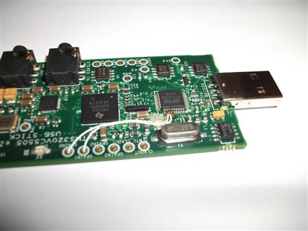
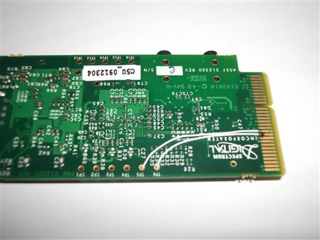
The whole kit comes in a small box (~13cm x 11cm x 4cm) and contains the USB stick itself along with a small 4 page leaflet and a small DVD (~1GB) containg the CCS 4 and a zip package containing useful examples for VC5505. The examples are centered around various peripherals on the DSP.
I wanted to go with the tools on the DVD, try the board and see how it is working and afterwards download and install the latest tools.
Tool installation & try-out
The installation process took me something like 10 minutes or so. Besides the installation of the Eclipse based CCS4 IDE, it installed the drivers needed for the board. I haven’t followed yet the steps to activate a licence. Without licence, Code Composer is limited to 30 days of evaluation.
I gave a particular attention to the leaflet since it was describing the necessary steps to be followed immediately after installation of the IDE.
- The first step is to create a target configuration. The settings you have to make in order to create a target configuration are described in detail into the leaflet. I also created 2 more targets. One for a cycle accurate C55 simulator and one for the functional C55 simulator
- Then we can import the workspace containing the example projects for VC5505. Here as well, the leaflet describes in great detail the needed steps.
- The leaflet contains some links to various resources
Then, I tried to run the LED blinker project but I got some errors on the compilation process. It turned out that I needed to set some paths in order to “help” the IDE find some additional files (headers and libraries).
Running/Debugging the LED blinker application
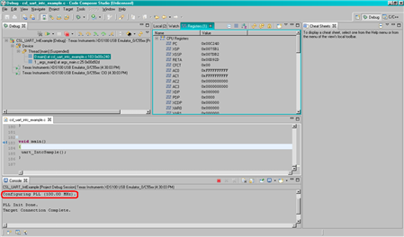
The LED blinker was the first project to be run onto this board. I have started a debugging session for the real target and also for the functional simulator
Debugging with the real target
The debugger is built around a FTDI chip (FT2232D) and its speed is limited to only 12Mbps. This makes it a little bit slow in the debugging/program loading process. More on the debugger later…
The total execution time for the project was around ~35seconds (having the PLL set at 100MHz by the GEL file)
Debugging with the C55 functional simulator
Running the same LED project on the functional simulator took me more than 10 minutes. A significant difference but I’d say the simulator can have a good use as well, at least when you need to run some signal processing task and you can only provide files.
HW extensions
- One of the things I would have liked to see was the USB signals tied at the expansion connecter. This would have offered some broader portfolio of possible application with the 5505 DSP
- The expansion connector is not a standard one. The pair connector is: SAMTEC - MEC1-130-02-S-D-NP-A
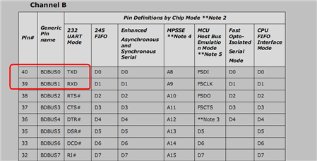
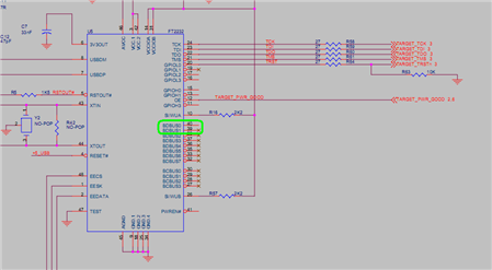
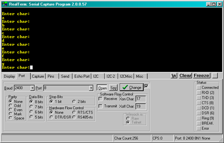
- USB-UART converter not used
o The UART pins are not tied with the Rx/Tx into the FTDI chip. This would have offered support for USB-serial port. I will try to connect the Rx/Tx UART pins from the spare FTDI channel B adapter to the UART pins of the DSP onto the expansion connector
Application building process
The TI support movies were very useful and they’d helped accelerate my first application. I attached a few links on the clips I have found most useful.
The samples provided at code.google.com have missing files and dependencies. I tried to reference the missing folders where the files in cause were found but I still miss some other files needed to run these projects. I will detail the application development in a following post.
USB details
The debugger is built around an FTDI device (FT2232D). This chip is a composite device and it presents 2 interfaces. One of the interfaces is used as a USB-serial port, while the remaining interface is used as an USB-JTAG adapter. Both of the interfaces are using 2 bulk endpoints each. This is important to know because the available USB full-speed bandwidth is split between the JTAG “interface” and the USB-serial port.
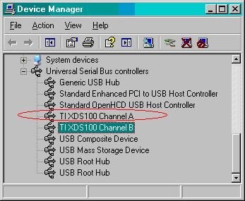
Channel A is used as JTAG, while channel B is used as USB-serial port emulator. When clicking on any of the devices there’s a choice of designating any of the channels as either USB-serial port or USB-JTAG interface.
I will continue on this review with my HW modifications and application(s).
Thanks for your patience!
Bogdan