


Simple exercise use the oscilloscope to display the signal generator. I'm not spending a lot of time here. This was not part of my application pitch. Just getting the unit configured (i.e. OS and network) has had it challenges. I'm taking this small detour just looking for win, something positive.
Using the small coax cable jumpers provided I connected IN1 to OUT1 and IN2 to OUT2. IN's being the scope and OUT's being the generator.
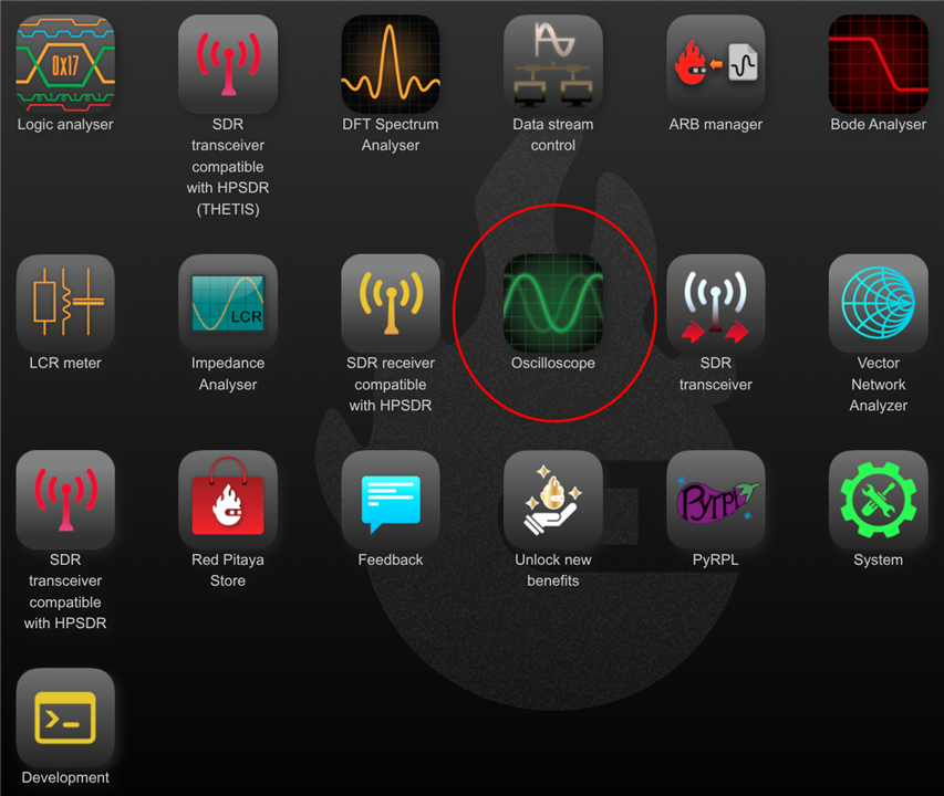
I thought I might performed the exercise without RTFM. That changed when I got to the application screen. No generator application. There is almost a paragraph for the label "SDR transceiver compatible with HPSDR (THETIS)" and you can't label Oscilloscope & Signal Generator. I used the quick start guide after that to look for things. Did I tell you the guide is old and doesn't reflect the menu accurately. Oh well, who cares about documentation.
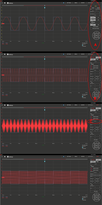
I have little experience with computer generated test equipment. I am also not a hunt a peck until I find what I am looking for type of person. I only stumbled across the configuration menu after RTFM. The menus were all gray so I didn't even peck at them. On the left of the screen are the menus. The menus changes between scope (A) and generator(B). On channel 1 I had a 1K square wave and on channel 2 a 1K sine wave. I then used the Frequency/Hz selection (C) to add zeros, 1000, 10000, 100000 & 1000000. Starting from the top screen shot I worked down. The waveform generator was responsive. I'm use to a dial and switches on the panel of test equipment to make changes. This was way more cool.
The third screen jumped out at me. One sine wave in one square. 10 sine waves in one square wave. Simple example. Now I didn't spend a lot of time changing settings. It was cool and appeared to work. I'm ignoring my incrementing the frequency waveform and calling this a win.
The device is hot to the touch. I mean hot enough I can't keep my finger on the heat sink. I put my winnings from the Spring Challenge to work and used the temperature probe to take a measurement.
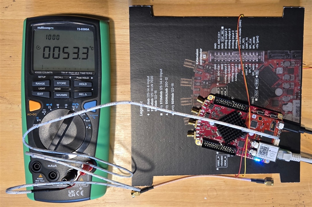
I don't have much experience but that seems hot to me. It stayed at that temperature during my scope test only fluctuating .1 of degree. Man I wish I had the metal case. You will note I am using the custom wire bound pinout card as a case. The weight of the cables connected to the end pulled the sucker of the bench one time so I had to design a fix. No need to worry. The wire is Teflon rated for plenums, it will take the heat.
Just below the card you can see the short coax jumper cable. I thought I took the picture when it was all assembled I guess not.
There is an oscilloscope and a signal generator that works. I flicked through some different wave forms and way cool how it changed. I'm taking this as a win!
The next time we chat I will have SDR'd. Talk later.


