Enrollment closes in
Days 0 Hours 0 Mins 0 Secs 0
![]()
Summary
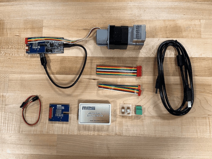
The TBMA732-Q-RD-00A is the round-version test board for the MagAlpha magnetic position angle sensor MA732. The MA732 sensor detects the absolute angular position of a permanent magnet, typically a diametrically magnetized cylinder on a rotating shaft. It comes mounted on a fully integrated smart motor solution for servo motor applications (EVKT-MSM942038-24). The MA732 is used for general purpose angle measurement, or on devices such as Angle Encoders, Automotive Angle or Speed Sensors, and Robotics.
RoadTest Goal
We want the roadtester to evaluate the MA 732: a 14-Bit, Digital, Contactless Angle Sensor with ABZ Incremental & PWM Outputs. It is capable of fast data acquisition & processing to provide accurate angle measurements at speeds from 0 to 60,000 rpm. The sponsor has prepared a testing and setup procedure (see next section) for ease of use for a hobbyist.
Discussion
How Would You RoadTest the MagAlpha Angle Sensor Kit?
Test Procedure
This kit comes with a servo BLDC motor which can be driven in speed or position mode via RS485. Attached to the rotor is a diametrically magnetized magnet which rotates with the motor rotor. Above this magnet is an MA702 with a 1-2 mm airgap.
Download the following document prepared for this roadtest on how the MA702 angle sensor can be read / evaluated. Instructions for running the motor via an Arduino MEGA and RS485 driver are included.
(MA732 Roadtest Setup Guide and Getting Started)
Product Variants
MPS offers several product variants:
| MA735 | MA780 | MA820 | MA310 |
| MA736 | MA782 | MA704 | MA302 |
| MA734 | MAQ470 | MA730 | MA102 |
| MA732 | MAQ430 | MA710 | MA850 |
| MAQ473 | MA800 | MA702 | MA330 |
MA732 - This is the product variant used for this roadtest.
Kit Contents
Hardware Technical Description
The MPS MagAlpha family of magnetic angle position sensors offers a revolutionary way to measure angles. The MagAlpha range offers unique performance advantages compared to rival magnetic sensing technologies.
MagAlpha sensors use the patented SpinAxisTM Hall measurement technique that provides instantaneous angle position in a digital format. SpinAxisTM uses a phase detection approach that eliminates any need for analog to digital conversion or complex angle calculation used by more traditional technologies. Click here for more information.
MA732 Angular Position Sensor
The MA732 detects the absolute angular position of a permanent magnet, typically a diametrically magnetized cylinder on a rotating shaft. Fast data acquisition and processing provide accurate angle measurements at speeds from 0 to 60,000 rpm. The digital filtering is adjustable to optimize control loop performance when used in servo applications.
The MA732 supports a wide range of magnetic field strengths and spatial configurations. Both end-of-shaft and off-axis (side-shaft mounting) configurations are supported.
The MA732 features magnetic field strength detection with programmable thresholds to allow sensing of the magnet position relative to the sensor for creation of functions, such as the sensing of axial movements or for diagnostics.
On-chip non-volatile memory provides storage for configuration parameters, including the reference zero angle position, ABZ encoder settings, and magnetic field detection thresholds. Click here for more information:
Features
TBMA732-Q-RD-00A Round Eval Board for MA732
The TBMA732-Q-RD-00A is the round test board for the MagAlpha magnetic position sensor MA732. This configuration is used for end shaft sensing.
It requires the communications kit (EVKT-MACOM) and the Macom App Software (see below) to evaluate MagAlpha functionality and performance with your set-up, such as noise level, refresh rate, power-up time, and magnetic field dependence.
In addition to this round test board, there is a long format version (LT) where the sensor is mounted on the edge of the board and can therefore be used in both side-shaft and end-of-shaft configurations. Click here for more information.
EVKT-MACOM MagAlpha Communication Kit
The EVKT-MACOM is a communication kit for the MagAlpha magnetic position sensor family. The EVKT-MACOM offers a seamless
connection and operation with MagAlpha test boards (TBMA) and evaluation kits (EVKTKNOB). The EVKT-MACOM kit contains a microcontroller motherboard, a collection of daughter boards adapted to different sensor boards, and the related cables. For more information CLICK HERE
Software
Additional Information
Important Dates
| Begin enrollment: | June 24, 2022 |
| End enrollment: | July 24, 2022 |
| Select RoadTesters: | July 29, 2022 |
| Ship unit date: | Aug 16 2022 |
| Begin RoadTesting: | Aug 23 2022 |
| Element14 follow up: | Sept 23 2022 |
| Post Reviews by: | Oct 23 2022 |
Terms and Conditions
Click Here to read the Terms and Conditions.
RoadTesters
shabaz due date Oct 23 2022
Guillaume_Martin due date Oct 23 2022
bac2348 due date Oct 23 2022
Cristi due date Oct 26 2022
DaveTheWalker due date Oct 26 2022
Top Comments
Interesting technology.
Does the kit come with a magnet? It is hard to tell from the image.
In this this type of sensor the magnetization geometry is important.
It would be nice to have magnet and BLDC motor bundled with kit for easier evaluation.
For beginers, there are nice video (https://www.monolithicpower.com/support/videos/unboxing-contactless-rotary-sensor…
Nice sensor. Here's a link to the datasheets:
https://www.farnell.com/datasheets/3541671.pdf
https://www.monolithicpower.com/en/documentview/productdocument/index/version/2/document_type/Datasheet…