RoadTest: RA2L1 EVK(Ultra-Low Power 48MHz Arm® Cortex®-M23)
Author: skruglewicz
Creation date:
Evaluation Type: Development Boards & Tools
Did you receive all parts the manufacturer stated would be included in the package?: True
What other parts do you consider comparable to this product?: Cypress PSoC6 EVK, NXP LPC55S69-EVK , NXP i.MXRT1170-EVK,Arduino Nano 33 IoT Board, Raspberry pi4, Advent AzureSphere EVK
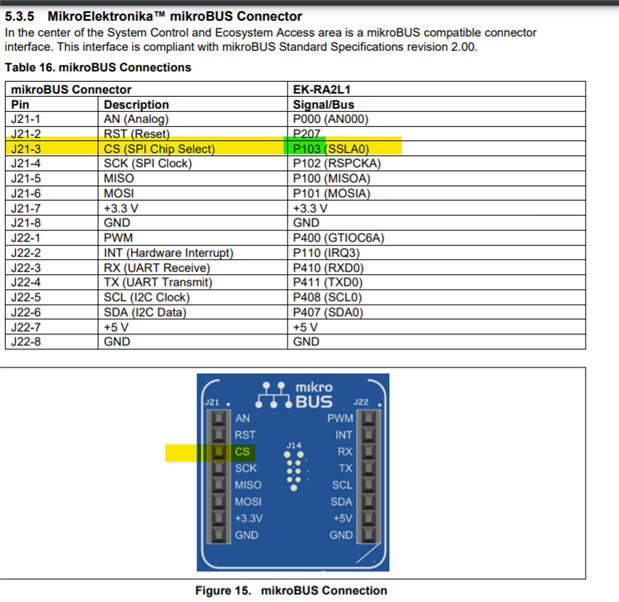
What were the biggest problems encountered?: Using the MikroE connector with a Relay Click Board. I was unable to get this working. I was able to finally get it to work but the documentation was giving a wrong pin assignment, which caused the problem. Also no Guidance in the Documentation on how to work with the MikroeE connector.
Detailed Review:
Updated 10/08/2021 -- I was able to get the MikroE Dual Relay Click working.
This Roadtest review will evaluate the Embedded Software Development capabilities of the EK-RA2L1, an evaluation kit for the Renesas RA MCU Group. The kit enables users to evaluate the features of the Renesas R7FA2L1AB2DFP MCU. It allows the user to develop and experiment with embedded applications using the Renesas toolchains, ' Flexible Software Package (FSP) and e2 studio IDE. Uses can utilize the rich on-board features along with a choice of popular ecosystem add-ons.
This review focuses on the development of embedded software, rather then the Hardware. The only hardware focus evaluated will be on attaching and programming a MikroE click board to the kit. I rated the product on the resources (examples, manuals, tutorials, videos and help available ) available for a hobbyist like myself with no prior knowledge of the EK-RA2l1.
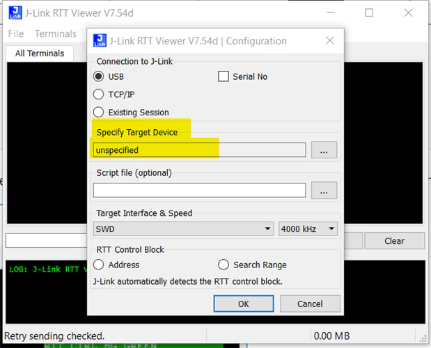
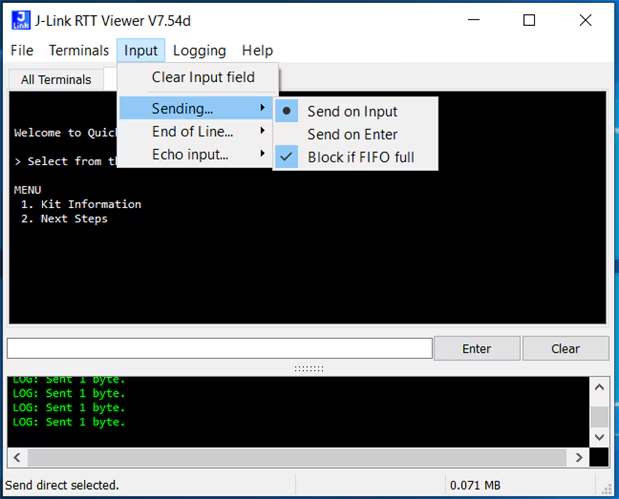
I will be experimenting with example programs available for the kit to gain knowledge with the toolchains FSP and e2 studio and SEGGER J-Link RTT Viewer. I will be, Connecting and Programming a MikroE Duel Relay Click board that I have acquired from other projects. I have no previous experience with the SEGGER J-Link RTT Viewer or the Renesas Flexible Software Package (FSP). This will be a learning experience for me. I have used Eclipse based IE's for NXP, Lattice, and Cypress PSoC6 EVK boards, so e2studio is not totally foreign to me.
I do not have an electronics background, but I am interested in IoT. My background is more on the software side, with a Bachelors of Science Degree in Computer Science from Boston University. I Graduated from BU in 1980 and had been working as a Software Engineer since then until I retired in 2018. I've been presently experimenting with IoT and I've used a few Development kits. I'm not keen on soldering (my dexterity is not as good as it use to be !) So, Development Kits allow me to experiment without soldering.
I will be evaluating the use and helpfulness of customer support on the R7FA2L1AB2DFP MCU, EK-RA2L1 kit and the Software Development Toolchains available. I will also be discovering and evaluating the available User Forums and Knowledge Base available on the Renesas Site, that hopefully will aid me in my experiments. I will also be using the Resources (Documentation, Video's, Tutorials ) available on the Renesas Website. I will be including links throughout my review and in the "references" section at the end of this review.
|
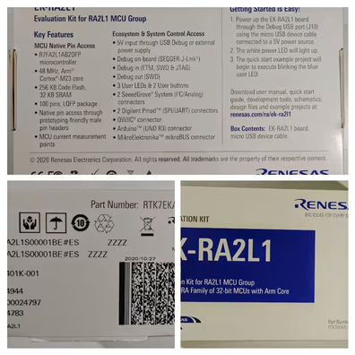
The Box
|
FRONT
|
||
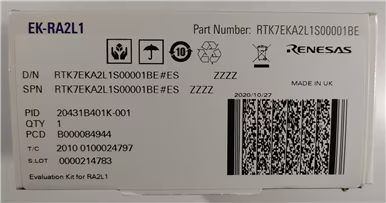 |
EK-RA2L1 Part Number: RTK7EKA2L1S00001BE D/N RTK7EKA2L1S00001 BE#ES MADE IN UK SPN RTK7EKA2L1S00001BE#ES ZZZZ 2020/10/27
Evaluation Kit for RA2L1 |
||
|
SIDE Cardboard Sheaths
|
BACK
|
||
|
The Contents of the box
|
FRONT
|
||
|
USB Cable
|
BACK
|
||
| The Quick Start Card |
|
||
 |
The world of big ideas awaits you! EK-RA2L1 is designed to fuel your creativity and enable effortless evaluation of the RA2L1 MCU group. Utilize rich on-board features with your choice of popular ecosystems add-ons to bring your big ideas to life.
We hope that you enjoy innovating with EK-RA2L1 as much as we enjoyed developing it.
EK-RA2L1 Resource renesas.com/ra/ek-ra211
RA Product Information renesas.com/ra Brings you to the RA product page RA Product Support Forum renesas.com/ra/forum brings you directly to the RA group Community Forum |
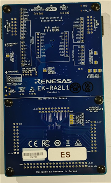
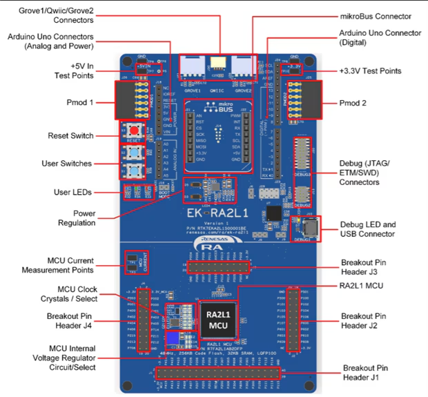
This section describes the board layout of the Kit. These photos were taken from the EK-RA2L1 v1 – User's Manual and are described here for review purposes.


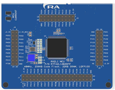


The first time I ran the tutorial , it did not flash the LEDs. I finally realized that the code was written for the EK-RA6M3 kit so the port names are wrong for the LED
//wrong port pin for leds
// should use array like blinky so it will work on all EVKs
//#define RED_LED_PIN BSP_IO_PORT_01_PIN_00
//#define GREEN_LED_PIN BSP_IO_PORT_04_PIN_00
// BSP_IO_PORT_05_PIN_03, ///< LED1 BLUE
// BSP_IO_PORT_05_PIN_04, ///< LED2 GREEN
// BSP_IO_PORT_05_PIN_05, ///< LED3 RED
#define RED_LED_PIN BSP_IO_PORT_05_PIN_05
#define GREEN_LED_PIN BSP_IO_PORT_05_PIN_04
/* LED type structure */
bsp_leds_t leds = g_bsp_leds;
/* Get pin to toggle */
//uint32_t pin = leds.p_leds[1];
const bsp_io_port_pin_t GREEN_LED = leds.p_leds[1];
const bsp_io_port_pin_t RED_LED = leds.p_leds[2];

10/04/2021 --- I'm stuck at this Point. I will keep working on a solution.
New
10/08/2021 -- I figured this out
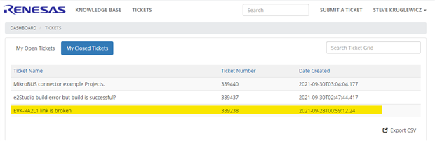
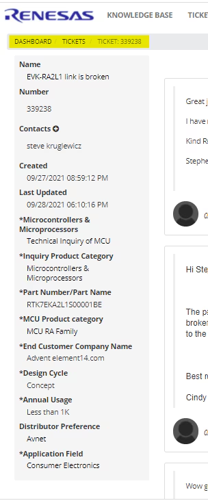
https://en-support.renesas.com/dashboard
https://en-support.renesas.com/mytickets
https://en-support.renesas.com/knowledgeBase
Summary & Conclusions


10/04/2021 --- I'm stuck at this Point. I will keep working on a solution.


I'm stuck at this point and need to answer some questions.


----------------------------------------------------------------------------------------------------------------------------------------------------------------------------------------

//------------------------------------------------------------------------------------------------------------------------------------------
// Modified Blinky code to toggle a MickroE Relay click board.
//J21-3 CS (SPI Chip Select) P103 (SSLA0)
//J22-1 PWM P400 (GTIOC6A)
#include "hal_data.h"
#include "r_ioport.h"
//#include "bsp_pin_cfg.h"
void R_BSP_WarmStart(bsp_warm_start_event_t event);
#define BSP_RELAY2 BSP_IO_PORT_01_PIN_04
#define RELAY1 BSP_IO_PORT_04_PIN_00
#define DELAY_MS 250
/*******************************************************************************************************************//**
* @brief Modified Blinky code to toggle a MickroE Relay click board
*
* replaces the LED port/pin in the call to module R_BSP_PinWrite()
* With the MickroE relay pin assignment
* The pin is set to HIGH then a delay and then set to LOW.
*
**********************************************************************************************************************/
void hal_entry (void)
{
#if BSP_TZ_SECURE_BUILD
/* Enter non-secure code */
R_BSP_NonSecureEnter();
#endif
/* Holds level to set for pins */
bsp_io_level_t pin_level = BSP_IO_LEVEL_LOW;
while (1)
{
/* Enable access to the PFS registers. If using r_ioport module then register protection is automatically
* handled. This code uses BSP IO functions to show how it is used.
*/
R_BSP_PinAccessEnable();
// Toggle Relay
//R_BSP_PinWrite(BSP_RELAY2, pin_level); // call needs to use local define BSP_RELAY2
R_IOPORT_PinWrite(&g_ioport_ctrl, RELAY2, pin_level); // RELAY2 is defined in FSP configurator and is the value of "Symbolic Name"
/* Protect PFS registers */
R_BSP_PinAccessDisable();
/* Toggle level for next write */
if (BSP_IO_LEVEL_LOW == pin_level)
{
pin_level = BSP_IO_LEVEL_HIGH;
}
else
{
pin_level = BSP_IO_LEVEL_LOW;
}
/* Delay */
R_BSP_SoftwareDelay(DELAY_MS, BSP_DELAY_UNITS_MILLISECONDS);
}
}
/*******************************************************************************************************************//**
* This function is called at various points during the startup process. This implementation uses the event that is
* called right before main() to set up the pins.
*
* @param[in] event Where at in the start up process the code is currently at
**********************************************************************************************************************/
void R_BSP_WarmStart (bsp_warm_start_event_t event)
{
if (BSP_WARM_START_RESET == event)
{
#if BSP_FEATURE_FLASH_LP_VERSION != 0
/* Enable reading from data flash. */
R_FACI_LP->DFLCTL = 1U;
/* Would normally have to wait tDSTOP(6us) for data flash recovery. Placing the enable here, before clock and
* C runtime initialization, should negate the need for a delay since the initialization will typically take more than 6us. */
#endif
}
if (BSP_WARM_START_POST_C == event)
{
/* C runtime environment and system clocks are setup. */
/* Configure pins. */
R_IOPORT_Open(&g_ioport_ctrl, g_ioport.p_cfg);
}
}
//------------------------------------------------------------------------------------------------------------------------------------------

This appendix contains the source code for the 2nd FSP manual tutorial.
#include "hal_data.h"
#include "bsp_pin_cfg.h"
#include "r_ioport.h"
#define RED_LED_NO_OF_FLASHES 30
//wrong port pin for leds
// should use array like blinky so it will work on all EVKs
//#define RED_LED_PIN BSP_IO_PORT_01_PIN_00
//#define GREEN_LED_PIN BSP_IO_PORT_04_PIN_00
// BSP_IO_PORT_05_PIN_03, ///< LED1 BLUE
// BSP_IO_PORT_05_PIN_04, ///< LED2 GREEN
// BSP_IO_PORT_05_PIN_05, ///< LED3 RED
#define RED_LED_PIN BSP_IO_PORT_05_PIN_05
#define GREEN_LED_PIN BSP_IO_PORT_05_PIN_04
extern bsp_leds_t g_bsp_leds;
#define RED_LED_DELAY_MS 125
#define GREEN_LED_DELAY_MS 250
volatile uint32_t delay_counter;
volatile uint16_t loop_counter;
void R_BSP_WarmStart(bsp_warm_start_event_t event);
/*******************************************************************************************************************/
void hal_entry (void)
{
//
/* LED type structure */
bsp_leds_t leds = g_bsp_leds;
/* Get pin to toggle */
//uint32_t pin = leds.p_leds[1];
const bsp_io_port_pin_t GREEN_LED = leds.p_leds[1];
const bsp_io_port_pin_t RED_LED = leds.p_leds[2];
/* Allow the WDT to run when the debugger is connected */
R_DEBUG->DBGSTOPCR_b.DBGSTOP_WDT = 0;
/* Open the WDT */
R_WDT_Open(&g_wdt0_ctrl, &g_wdt0_cfg);
/* Start the WDT by refreshing it */
R_WDT_Refresh(&g_wdt0_ctrl);
/* Flash the red LED and feed the WDT for a few seconds */
for (loop_counter = 0; loop_counter < RED_LED_NO_OF_FLASHES; loop_counter++)
{
/* Turn red LED on */
//R_IOPORT_PinWrite(&g_ioport_ctrl, RED_LED_PIN, BSP_IO_LEVEL_LOW);
R_IOPORT_PinWrite(&g_ioport_ctrl, RED_LED_PIN, BSP_IO_LEVEL_LOW);
/* Delay */
R_BSP_SoftwareDelay(RED_LED_DELAY_MS, BSP_DELAY_UNITS_MILLISECONDS);
/* Refresh WDT */
R_WDT_Refresh(&g_wdt0_ctrl);
//R_IOPORT_PinWrite(&g_ioport_ctrl, RED_LED_PIN, BSP_IO_LEVEL_HIGH);
R_IOPORT_PinWrite(&g_ioport_ctrl, RED_LED, BSP_IO_LEVEL_HIGH);
/* Delay */
R_BSP_SoftwareDelay(RED_LED_DELAY_MS, BSP_DELAY_UNITS_MILLISECONDS);
/* Refresh WDT */
R_WDT_Refresh(&g_wdt0_ctrl);
}
/* Flash green LED but STOP feeding the WDT. WDT should reset the
* device */
while (1)
{
/* Turn green LED on */
//R_IOPORT_PinWrite(&g_ioport_ctrl, GREEN_LED_PIN, BSP_IO_LEVEL_LOW);
R_IOPORT_PinWrite(&g_ioport_ctrl, GREEN_LED, BSP_IO_LEVEL_LOW);
/* Delay */
R_BSP_SoftwareDelay(GREEN_LED_DELAY_MS, BSP_DELAY_UNITS_MILLISECONDS);
/* Turn green off */
//R_IOPORT_PinWrite(&g_ioport_ctrl, GREEN_LED_PIN, BSP_IO_LEVEL_HIGH);
R_IOPORT_PinWrite(&g_ioport_ctrl, GREEN_LED, BSP_IO_LEVEL_HIGH);
/* Delay */
R_BSP_SoftwareDelay(GREEN_LED_DELAY_MS, BSP_DELAY_UNITS_MILLISECONDS);
}
}
/*******************************************************************************************************************/
void R_BSP_WarmStart (bsp_warm_start_event_t event)
{
if (BSP_WARM_START_RESET == event)
{
#if BSP_FEATURE_FLASH_LP_VERSION != 0
/* Enable reading from data flash. */
R_FACI_LP->DFLCTL = 1U;
/* Would normally have to wait for tDSTOP(6us) for data flash recovery. Placing the enable here, before clock and
* C runtime initialization, should negate the need for a delay since the initialization will typically take more than 6us. */
#endif
}
if (BSP_WARM_START_POST_C == event)
{
/* C runtime environment and system clocks are setup. */
/* Configure pins. */
R_IOPORT_Open(&g_ioport_ctrl, &g_bsp_pin_cfg);
}
}
|
REFERENCESThis section contains links to resources I used in this review |
||||||||||||||||||||||||||||||||||||||||||||||||||||||||||||||||||||||||||||||||||||||||||||||||||||||||||||||||||||||||||||||||||||||||||||||||||||||||||||||||||||
|---|---|---|---|---|---|---|---|---|---|---|---|---|---|---|---|---|---|---|---|---|---|---|---|---|---|---|---|---|---|---|---|---|---|---|---|---|---|---|---|---|---|---|---|---|---|---|---|---|---|---|---|---|---|---|---|---|---|---|---|---|---|---|---|---|---|---|---|---|---|---|---|---|---|---|---|---|---|---|---|---|---|---|---|---|---|---|---|---|---|---|---|---|---|---|---|---|---|---|---|---|---|---|---|---|---|---|---|---|---|---|---|---|---|---|---|---|---|---|---|---|---|---|---|---|---|---|---|---|---|---|---|---|---|---|---|---|---|---|---|---|---|---|---|---|---|---|---|---|---|---|---|---|---|---|---|---|---|---|---|---|---|---|---|---|
The Starter Page
|
||||||||||||||||||||||||||||||||||||||||||||||||||||||||||||||||||||||||||||||||||||||||||||||||||||||||||||||||||||||||||||||||||||||||||||||||||||||||||||||||||||
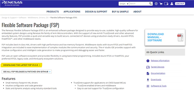
FSP Page
|
||||||||||||||||||||||||||||||||||||||||||||||||||||||||||||||||||||||||||||||||||||||||||||||||||||||||||||||||||||||||||||||||||||||||||||||||||||||||||||||||||||
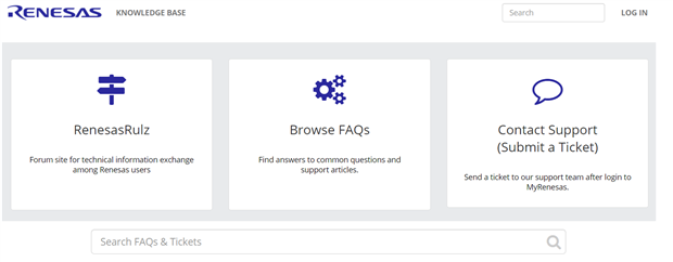
Support PortalTechnical Support Requesthttps://en-support.renesas.com/dashboard Knowledge Basehttps://en-support.renesas.com/knowledgeBase Community Forum |
||||||||||||||||||||||||||||||||||||||||||||||||||||||||||||||||||||||||||||||||||||||||||||||||||||||||||||||||||||||||||||||||||||||||||||||||||||||||||||||||||||
Training Video's
|
||||||||||||||||||||||||||||||||||||||||||||||||||||||||||||||||||||||||||||||||||||||||||||||||||||||||||||||||||||||||||||||||||||||||||||||||||||||||||||||||||||