RoadTest: ROHM 8-Channel Multi-Rail DC/DC Converter Board
Author: manojroy123
Creation date:
Evaluation Type: Power Supplies
Did you receive all parts the manufacturer stated would be included in the package?: True
What other parts do you consider comparable to this product?: They should provide some basic information about how to use it with 12 volt SMPS
What were the biggest problems encountered?: Not able to quickly refer to document since they never provided with paper documentation. I would highly recommend ROHM to provide with some basic paper documents with the product for quick execution for user
Detailed Review:
Unboxing of ROHM Multi-Rail DC/DC Converter Board
The box has a size of 13cm X 9cm as shown in the figure 1
Figure 1
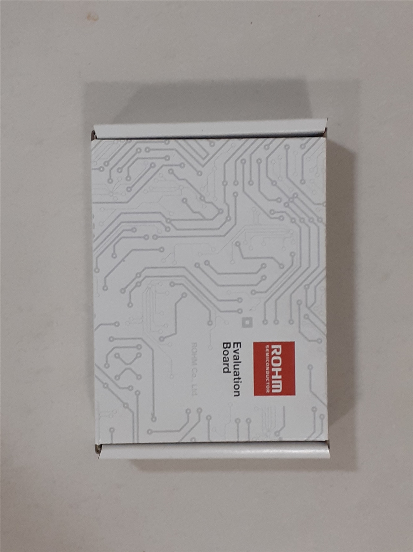
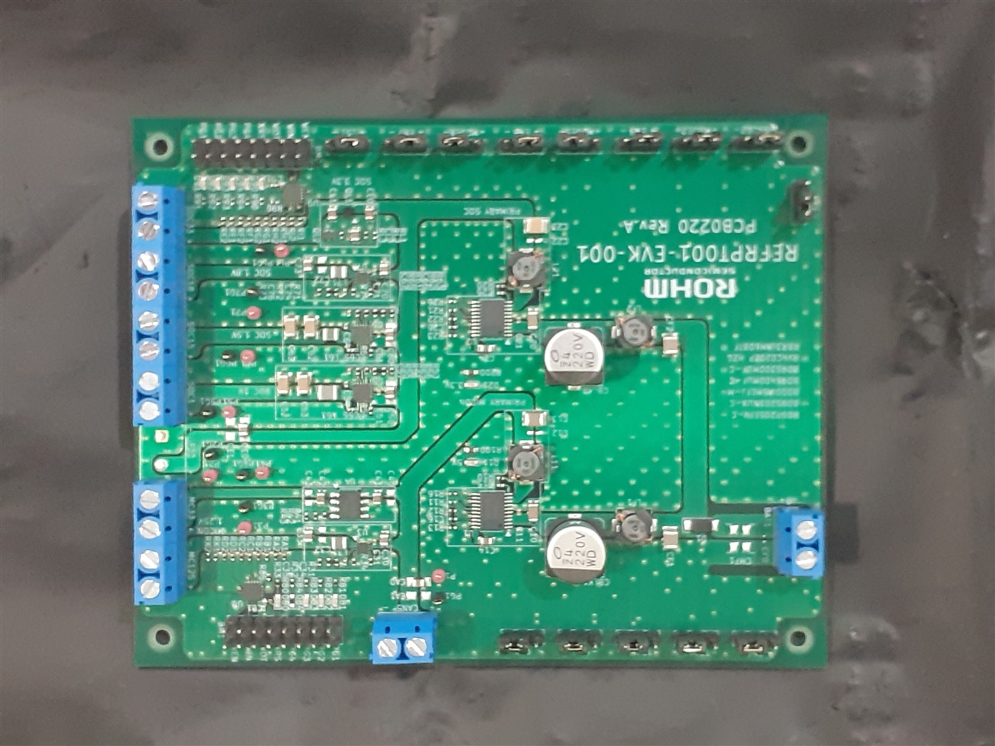
Inside the box you get an evaluation board covered on a black plastic shielded with Grey EMI absorbing spung shown in figure 2.
Figure 2

Figure 3 has an actual evaluation board
Figure 3
Introduction
Description and Overview
The REFRPT001-EVK-001 is a power tree solution reference board specifically designed for Infotainment devices such as vehical electronic instrumentation cluster,vehical digital instrumentation panel, vehical digital dashboard or for advanced driver asistance system ECU. The board provides Good EMC performance that meets CISPR25 Class 5 even when all power Rails are operating, and reduces heat generation of each device by distributing high-efficiency DCDC.
System block diagram:-

Some question that need to be answered
What is voltage monitoring ?
An application that can monitor system voltage in real time, and provide operators with warning in the event that system voltages are nearing or exceeding limits.
Why do we need voltage monitoring ?
To proctect to Soc, MCU and periferals that is connected to the system from either under voltage or overvoltage. This are important function when dealing with microcontroler or with microporcesor system with operating system in it. This can hit the OS to execute certain function to shurtdown system properly.
What is power tree ?
The power tree illustrates the main supply power flow through a tree of power converters that convert the main supply power to the voltage and current required to drive various loads.
Why do we need power tree ?
Different ic has different voltage and current requirement. To handle each of the requirement properly we us power tree solutions.
What is functional safety ?
Functional faliure of certain parts of the system shouldent affect the entire system is called functional safety.
Why do we need functional safety in Dc to Dc convertor system ?
So that The Ic can detect potential failure of the power supply IC itself without affecting existing systems.
How does it achieves functional safety ?
The system uses BIST (Build in self test to achieve functional safety)
What is BIST(built in self test)?
A built-in self-test (BIST) or built-in test (BIT) is a mechanism that permits a machine to test itself. Engineers design BISTs to meet requirements such as:
· high reliability
· lower repair cycle times
or constraints such as:
· limited technician accessibility
· cost of testing during manufacture
The main purpose [1] of BIST is to reduce the complexity, and thereby decrease the cost and reduce reliance upon external (pattern-programmed) test equipment. BIST reduces cost in two ways:
1st reduces test-cycle duration
2nd reduces the complexity of the test/probe setup, by reducing the number of I/O signals that must be driven/examined under tester control.
Both lead to a reduction in hourly charges for automated test equipment (ATE) service.
What is power good signal ?
The Power Good signal (power-good) is a signal provided by a computer power supply to indicate to the motherboard that all of the voltages are within specification and that the system may proceed to boot and operate.
Why do we need power good signal ?
The power good signal is send by voltage monitoring ic to indicate that all the output power is stabalized and the system can start executing it’s operations.
How does power good signal works in a system ?
In the absence of Power_Good, the timer chip holds the reset line on the processor, which prevents the system from running under bad or unstable power conditions.When the timer chip receives the Power_Good signal, it releases the reset, and the processor begins executing whatever code is at address FFFF:0000 (usually the ROM BIOS).
What happens when power good signal goes low while system is working ?
Many time power good signal is connected to the NMI (Non maskable interrupt) hardware interrupt pin of the microprocessor or microcontroler system. The system has to execute NMI operation irrespective of the any operation that is be performed. This is the highest priority interrupt. It typically occurs to signal attention for non-recoverable hardware errors.
What is watch dog timer ?
A watchdog timer (sometimes called a computer operating properly or COP timer, or simply a watchdog) is an electronic or software timer that is used to detect and recover from computer malfunctions. Watchdog timers are widely used in computers to facilitate automatic correction of temporary hardware faults, and to prevent errant or malevolent software from disrupting system operation.
Why do we need watch dog timmer ?
During normal operation, the computer regularly restarts the watchdog timer to prevent it from elapsing, or "timing out". If, due to a hardware fault or program error, the computer fails to restart the watchdog, the timer will elapse and generate a timeout signal. The timeout signal is used to initiate corrective actions. The corrective actions typically include placing the computer and associated hardware in a safe state and invoking a computer reboot.
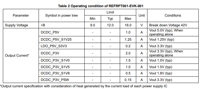
Operating conditions:-
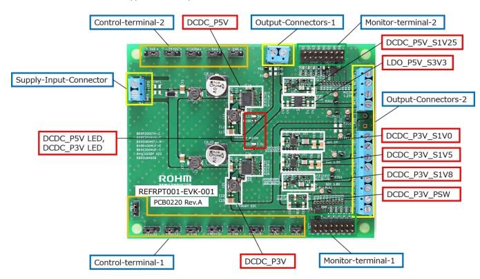
Location of components:-
The Test
1)measuring the switching noise jitter ?
Most Ic whoes power i.e Vcc and Gnd is bypass Using capacitor will have a switching noise jitter even when not connected to power supply. [What is a switching noise jitter ? This are jitter that is noticed at the output of the ic because of internal transistor switching] Figure 1 Shows the switching noise jitter of the ic which is around 100 milivolt peak to peak. Whcih is big concern to me
Figure 1
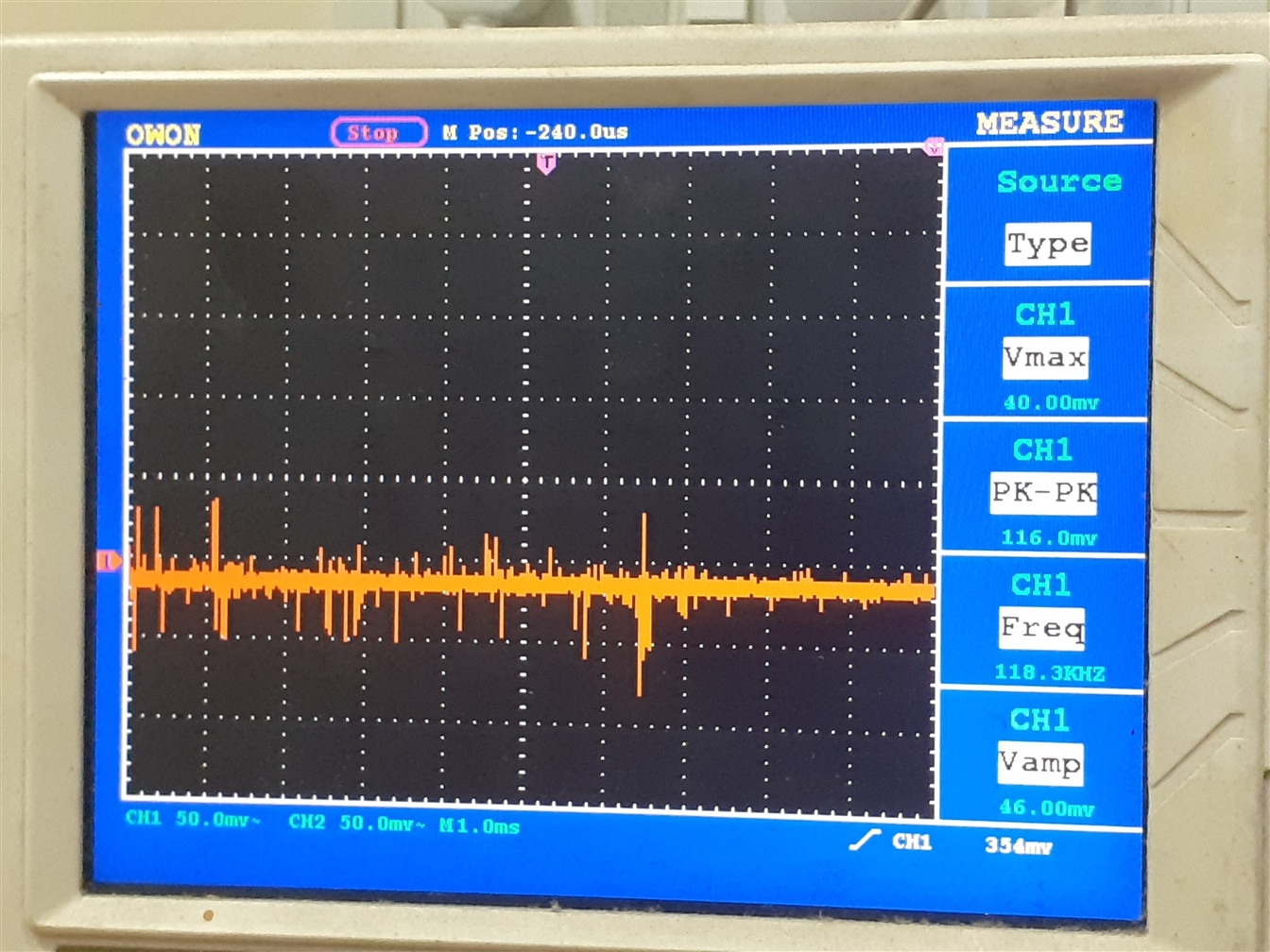
Figure 2 is the FFT graph of the switching noise jitter
Figure 2
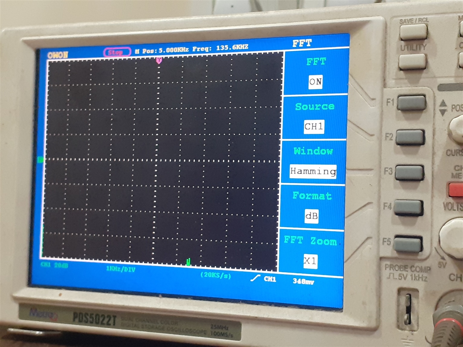
You can see peak at 6.5khz spectrum
1) I will connect the system to an automotive 12 volt battery and test the system out for jitter, ringing noise and ripples.
Figure 1 shows the switching noise jitter at CAN output of the evaluation boad. The CAN output has a 5Volt regulated output. The evaluation board is connected to the 12 volt car Battery.
Figure 1
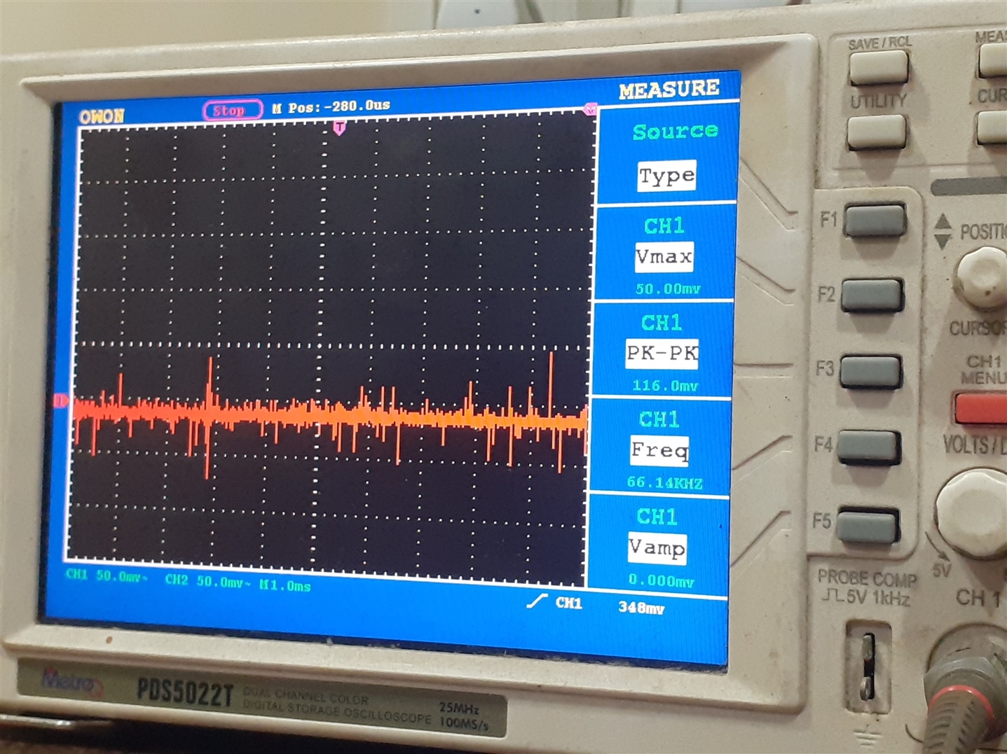
In the above figure you can see the switching noise jitter. Except for switching noise jitter there is no other noise’s like ripple noise, transisant ringing etc. The evalution board and design seems to be very good design since we are not seeing any ripple voltages. Figure 2 shows the FFT graph when connected to 12 volt car battery.
Figure 2
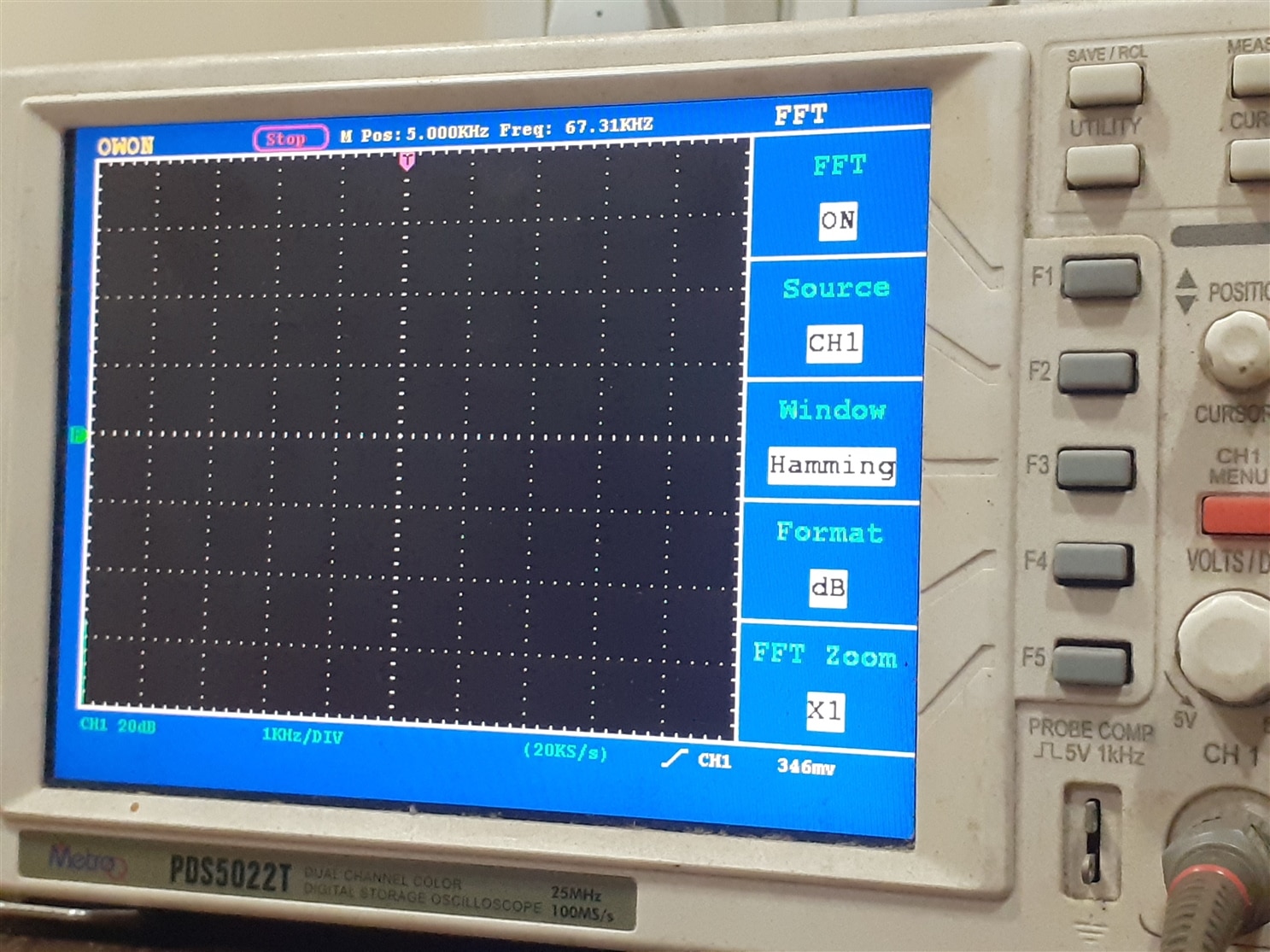
In this FFT graph you cn see that there is no noise after connecting it to 12 volt car battery.
3) Testing system with 12 volt SMPS for Voltage Monitor and Power good Signal ?
I have connected the system to 12 volt SMPS power supply as shown in figure 1 bellow.
Figure 1
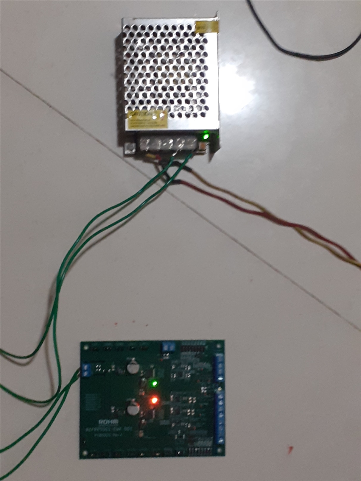
From the figure 1 you can see that 5 volt and 3.3 volt lights has turned on. It means that the Primary DC to DC convertor has started functioning and it’s converting the voltage to it’s appropriate voltages.
Now we will check for the power good signal for all the power rails. If the Light of the power good signal is on it means that it is providing proper output voltages or the output voltage is within the specification as you can see it on Video 2 bellow.
You don't have permission to edit metadata of this video.
4)Testing system with 12 volt SMPS for jitter, ringing noise and other ripples ?
SMPS produces various types of noise such as jitters, ringing transiant noise and ripples they are all of various frequency as you can see in the figure 1 bellow.
Figure 1
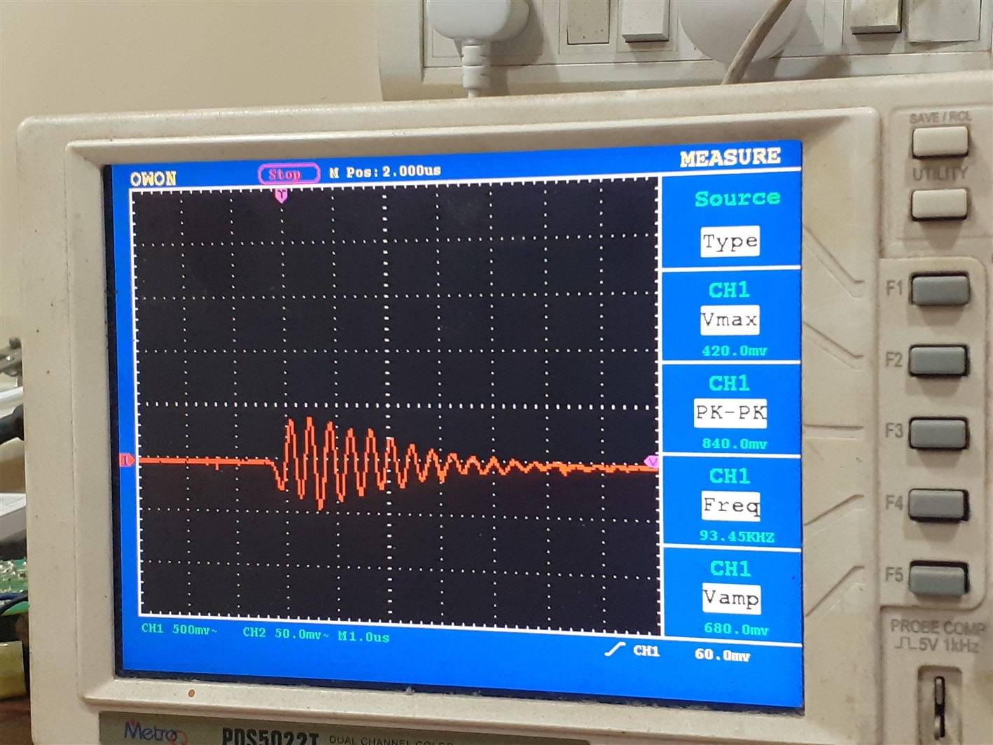
Figure 2
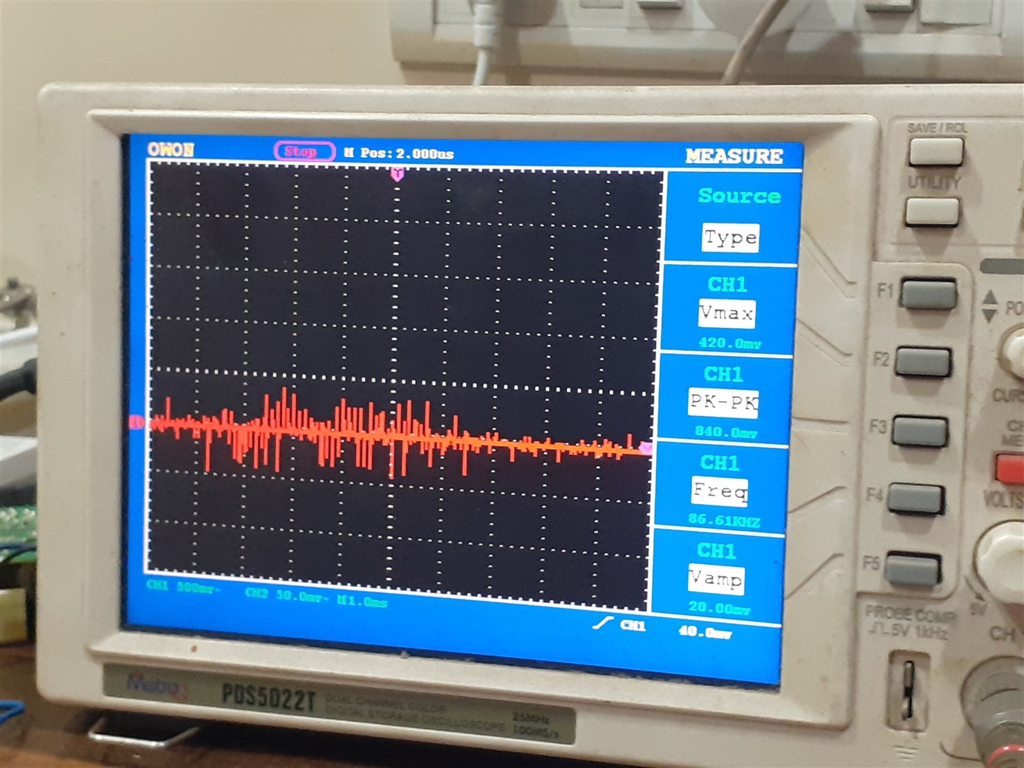
Figure 3
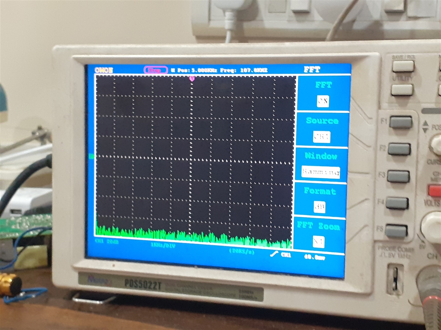
Figure 3 shows the FFT spectrum graph of the 12 volt power supply. In this graph you can see the present of harmonics and it’s strength. The graph does show presents of harmonics above 1khz. The prower supply does have an inbuilt filter but it havent reduce presents of harmonics of various noise into negligible. To know more about SMPS noise you can check my blog bellow.
blog link:- https://community.element14.com/challenges-projects/design-challenges/experimenting-with-magnetic-components/b/blog/posts/experiment-with-magnetic-component---blog-5-main-experiment
In this experiment we will see How much of thoes SMPS noise are reflected in the output of the DC to DC convertor system.
Figure 4
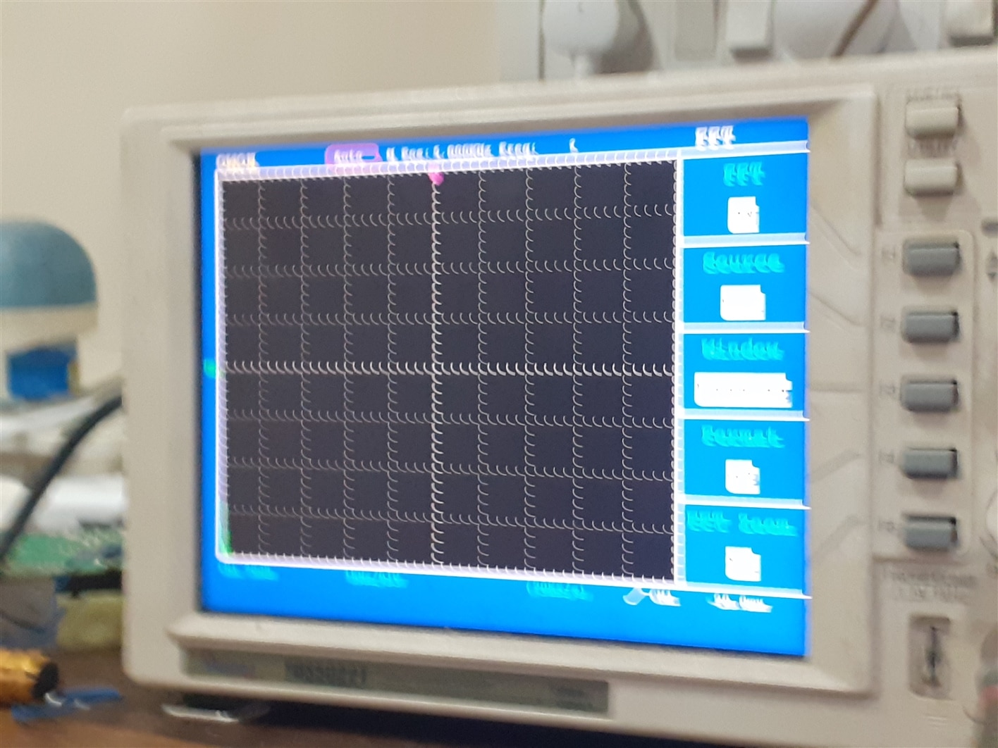
Figure 4 show FFT spectrum graph of the CAN output of the ROHM DC to DC convertor. Over here you can see all the low frequency harmonics have been substaintialy reduce to negligable level.
5) Will the system pass all the power integrity requirement of Most IC such as SOC, MCU etc, When used wiith 12 volt SMPS ?
To know about power integrity you can check my blog. whoes link is given bellow
blog Link:- https://community.element14.com/challenges-projects/design-challenges/experimenting-with-magnetic-components/b/blog/posts/experiment-with-magnetic-component---reducing-transient-noise-in-smps
For most SOC,MCU that has a voltage requirement of 3.3 volt or bellow they have noise requirement of 2% or less. Which is given in my blog. Figure 1 shows the peak to peak noise of the output of the 3.3 volt power rail.
Figure 1
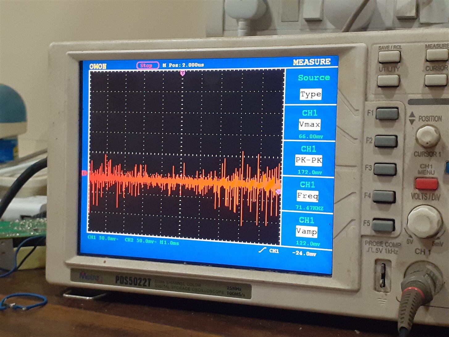
From the above figure you can see the Peak to Peak noise voltage is around 100 milivolt and above, which fails the requirement for 3.3 volt SOC which is around 66 milivolt or bellow.
For more information about Power integrity issue Please check the blog link given bellow.
Conclusion:-
Overall the boad is a good design when used with Pure DC source such as battery. But for using it with SMPS you need to cacade a good filter that would attenuate every noise comming from SMPS to bellow 100 microvolt. Then the board can be used with 12 volt SMPS also.
Some comment:-
The evaluation board should come with some basic proper paper documentation. Because when dealing with board like this. We need to quickly refer to the paper document than scroll a PDF. Hope my this comment will be taken under consideration by ROHM.