RoadTest: ADP3450 Analog Discovery Pro USB Oscilloscope
Author: MARK2011
Creation date:
Evaluation Type: Test Equipment
Did you receive all parts the manufacturer stated would be included in the package?: True
What other parts do you consider comparable to this product?: The whole family of Analog Discovery by Digilent. And of course, PICO portable oscilloscopes can be compared with ADP3450 Analog Discovery Pro USB Oscilloscope
What were the biggest problems encountered?: I didn't manage to conduct properly tracer task. It isn't oscilloscope fault, for sure but in my opinion description isn't clear enough.
Detailed Review:
Starting from a big thank you for trust and choosing me.
I will try my best to tell you about my experiences with the ADP3450 Analog Discovery Pro USB Oscilloscope
At this point, I admit at the very beginning working with this device was a great pleasure
but I found out that I have tremendous stage Wright now, while writing these words.
I have competed in many road tests, shared my experiences with many sets, but here I feel serious and responsible. I realized what a responsible task and how advanced a device I am dealing with.
My guess is that it's best to “less the waffle” and get down to business
I need also to start from admiration of Digilent, the outstanding company with over 20 years of activity on the electronic market, now one of the brilliant subsidiaries of NI, specialized in FPGA equipment, development boards/kits and - which is particular in our case - portable USB test and measurement devices.
To quote their motto” We provide the (brilliant*) building blocks and you provide the brilliance.
Yes, indeed the previous hits Analog Discovery Analog Discovery 2 and indisputably - the rising star - our Analog Discovery Pro are on the top of popularity and good assessment among engineers, students as well hobbyists. The phenomena of portable instruments to measure, visualize, generate, record, and control mixed-signal circuits is still alive. Nevertheless Digilent introduced the expanded version:
Analog Discovery Pro 3000 - series of USB, PC-based oscilloscopes
At the expense of sizes (if you need the tool easy to keep in your pocket AD II is still the best solution) we get professional benchtop equipment. Number of available choices and features for measurements makes you intimidated. Nevertheless, it is very handy and intuitive. For me, according to short but intensive experience the flexibility of available functions and features is invaluable.
It is clear that this range has been selected based on experience with previous instruments series. It seems also to be a response to customers expectations. The range was extended to four channel converters with known from professional solutions, 14-bit resolution at up to 0.5 GS/s. 16 dedicated digital channels is the right answer for those who deal with the digital realm.The name “mixed signal” is truly deserved. In one box we get digital power supply, digital outputs, two channel arbitrary waveform generator, and two dedicated external triggers.
It cannot be overlooked that Analog Discovery Pro scopes come ready to use with WaveForms free software sharing 12 instruments to view, analyze and register data from mixed signal systems. With The 3000 series, Digilent introduced the idea of Linux Mode which provides an on-device terminal-based operating system. Together with WaveForms SDK it makes a great platform for customization and individual extension of capabilities. Next to the improvements above
The series is also known for advanced triggering options. Some are worth emphasizing cross-triggering, activating based on a received and decoded protocol. Two external trigger inputs can’t be unnoticed.
Talking particularly about the ADP3450 Analog Discovery Pro I promised myself not to multiply data easily available and shared but some information must be shown and discussed .
What we get:
Four analog input channels
accessible via front panel through BNC connectors used in:
Oscilloscope,
Network Analyzer,
Spectrum Analyzer,
Voltmeter,
Impedance Analyzer,
Data Logger.
with parameters as follow:
Channel type: single ended
Analog bandwidth: 55+ MHz @ 3 dB
Noise limiting hardware bandwidth filter: 20 MHz (Can be disabled)
14-bit resolution (16-bit resolution with oversampling)
Input range ±25 V (±50 V diff)
Input protected to ±50 V
Max sampling rate:
0.5 GS/s (with oversampling enabled)
100 MS/s default
AC or DC coupling
Input buffer Size
128 MS total in record mode
32 k + samples per channel in repeated/shift/screen modes
Two Analog Outputs channels
provided by arbitrary waveform generator,
also accessible via front panel with BNC connectors standard
Used in:
Waveform Generator,
Impedance Analyzer,
Network Analyzer
with parameters as follow:
14-bit Resolution
AC amplitude (max): ±5 V
Analog bandwidth: 15 MHz @ 3 dB
Maximum Sampling Rate: 125 MS/s
Digital Power Supply:
One Power supply with two access points
Voltage Range: 1.2 V to 3.3 V
Output Current: 300 mA
Digital Inputs and Outputs:
Used in the Logic Analyzer, Pattern Generator, Protocol Analyzer, and Digital I/O
Channels: 16
Input logic standard: LVCMOS (adjustable 1.2 V to 3.3 V, 5 V tolerant)
Output logic standard: LVCMOS (adjustable 1.2 V to 3.3 V, 8 mA)
Max sampling rate: 125 MS/s
Logic analyzer buffer memory:
64 MS total in Record Mode
32 k+ per channel in Repeated/Shift/Screen modes
Advanced Triggering:
Trigger sources: oscilloscope analog channels, function generator start, digital I/O lines,
external triggers, manual trigger button
Trigger Modes
None, auto, manual (forced trigger), single
Analog Trigger
Edge, pulse, transition, condition, level, hysteresis, hold-off
Digital Trigger
Edge, level, pattern, glitch, protocol
The oscilloscope can be connected to computer via USB or using the Ethernet connection (in Linux or Standard Modes)
there are also 4 High-speed USB 2.0 ports for peripheral connection enabled in Linux mode
Ports can be used WiFi dongles (in Linux Mode)
Regarding ADP3250 There are no other specification differences between the ADP3450 and ADP3250.
detailed specification: https://digilent.com/reference/test-and-measurement/analog-discovery-pro-3x50/specifications
and some nice details in advertisement https://www.youtube.com/watch?v=-lMlnb6_Kdw
Without dedicated software, USB oscilloscopes would remain a nice and sophisticated (and relatively expensive) piece of electronic stuff. Only the program is their soul and brings to life.
In the case of Digilent products we got a WAVEFORM program system satisfying even extended needs of advanced users.
WaveForms is the free software application for the ADP3450 and ADP3250 and enables use of the available analog and digital instruments. Digilent is proud announcing that software has been refined by customer feedback for over 10 years and features a computer and laptop friendly user interface that has the feel of traditional benchtop software.
The device communicates with WaveForms via a USB or ethernet connection to the computer, allowing users to capture, record, analyze, and generate mixed signal and mixed domain waveforms. WaveForms can be tested without hardware using its demo mode feature. In addition to the use of instruments in the application, the WaveForms application has a script editor tool, which allows custom scripting of the instrument in JavaScript. For even more customization potential, the WaveForms Software Development Kit (SDK) can be used to create custom applications and scripts in Python, C and additional languages.
modules called “instruments” available in the WaveForms
The ADP3450 also has Linux Mode, which boots a terminal based Linux distribution onto the device itself. When running as an embedded device, the ADP3450 or ADP3250 adds additional flexibility and connectivity to WaveForms SDK. When scripts are run on the device data can be stored locally or streamed via a wired or wireless connection. The ADP3450 and ADP3250 also have four USB ports, that are enabled in Linux mode, allowing for the connection of peripherals, such as a WiFi dongle.
Features of WaveForms
Oscilloscope
Waveform Generator
Voltage Supply
Data Logger
Logic Analyzer
Pattern Generator
Static I/O
Network Analyzer
Spectrum Analyzer
Waveforms details: https://digilent.com/shop/software/digilent-waveforms/
The time has come for: Overview of available documentation and online support -
Digilent oscilloscopes are very well documented by producer as well there are myriads of helpful materials on the net.
Analog Discovery Pro USB Oscilloscope is accompanied with well prepared series of tutorials
Projects
During the roadtest I used and got support from (too) many sources. Sometimes I got confused about excess But getting information was generally quick and easy.
It is hard to say which source of knowledge about our device is more or less important. They all complement each other. At work with ADP I tried to record my actions when learning about a new device.
In order not to repeat the search for documentation in the future, to assess which material is practical, useful for me, and what is important.
I prepared the set of useful links below:
At Digilent site - the main page for Analog Discovery Pro (ADP3450/ADP3250)
https://digilent.com/reference/test-and-measurement/analog-discovery-pro-3x50/start
Analog Discovery Pro (ADP3450/ADP3250) Specifications
https://digilent.com/reference/test-and-measurement/analog-discovery-pro-3x50/specifications
Test and Measurement Guides
https://digilent.com/reference/test-and-measurement/guides/start
PDF: Analog Discovery Pro (ADP3450/ADP3250) Reference Manual
https://www.farnell.com/datasheets/3210246.pdf?COM=RoadTests&Reviews
https://digilent.com/reference/test-and-measurement/analog-discovery-pro-3x50/reference-manual
Analog Discovery Pro (ADP3450/ADP3250) Getting Started Guide
https://digilent.com/reference/test-and-measurement/analog-discovery-pro-3x50/getting-started-guide
WaveForms Reference & Manual & getting-started-guide
https://digilent.com/reference/software/waveforms/waveforms-3/start
https://digilent.com/reference/software/waveforms/waveforms-3/reference-manual
https://digilent.com/reference/software/waveforms/waveforms-3/getting-started-guide
Online manual from Digilent will be useful for advanced as well as for these who need some introduction in “oscilloscopes basics” these tutorials are very convenient:
Using the Oscilloscope
https://digilent.com/reference/test-and-measurement/guides/waveforms-oscilloscope
There are 12 “lessons” for each WaveForms instrument and additional supporting Using the Script Editor, Linux Mode, External Triggers, streaming data over internet as well as adding GUI for Linux
lots of knowledge in extremely convenient form - totally free. Thank you Digilent!
Using ADP Pro and WaveForms I looked for support also on sites dedicated to former Analog Discovery modules. That is valuable specially on foras: official Digilen’s https://forum.digilentinc.com/ as well many others on hackster, or even element14.com
There are a lot of materials on youtube also.
Stepping back for a while to ADP parameters I wanted to check limitations in this scope (sic!)
Can an improper computer limit the features of the oscilloscope or prevent it from being used? How about other circumstances, limits etc...?
Operating conditions, restrictions and warnings for the user as well as warranty terms and exclusions of this guarantee - this may be important!
Happily,I didn’t find serious limitations I decided to run WaveForms on my old “workshop” laptop
HP Probook with I5 & 8G and WIN10
According to manuals, Vista, 7, and 8 may be functional but are not officially supported
Safety
Oscilloscope meets the requirements of electrical equipment safety standards for measurement, control, and laboratory use:
IEC 61010-1, EN 61010-1
UL 61010-1, CSA 61010-1
regarding Electromagnetic Compatibility
Emissions
EN 61326-1:2013 (IEC 61326-1:2012), Class A
IEC CISPR 11: 2015 / A1: 2016 (Ed 6.1)
Immunity
EN 61326-1:2013 (IEC 61326-1:2012), Basic
EN 61000-3-2: 2014
EN 61000-3-3: 2013
IEC 61000-4-2: 2008
IEC 61000-4-3: 2006 / A1: 2007 / A2: 2010
IEC 61000-4-4: 2012
IEC 61000-4-5: 2014 / A1: 2017
IEC 61000-4-6: 2013 / COR1: 2015
IEC 61000-4-8: 2009
IEC 61000-4-11: 2004 / A1: 2017
CE Compliance
2014/35/EU; Low-Voltage Directive (safety)
2014/30/EU; Electromagnetic Compatibility Directive (EMC)
RoHS Directive 2011/65/EU as amended by Directive (EU) 2015/863
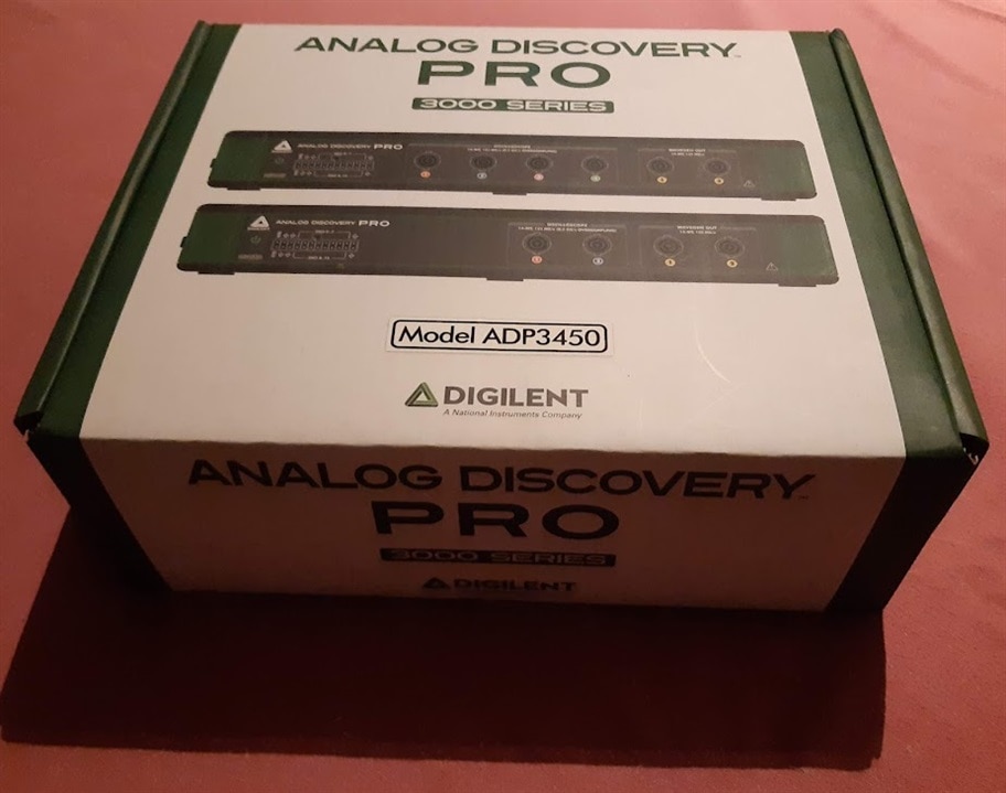
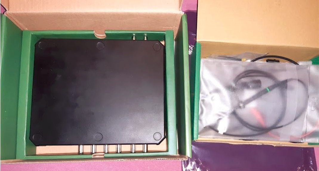
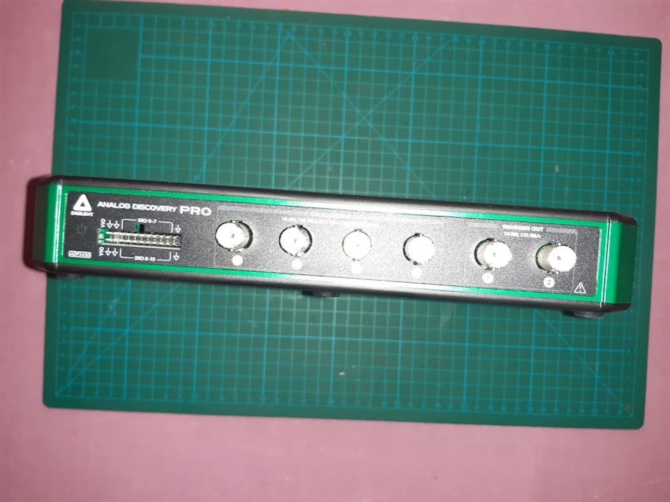
As obvious I Started from obviously obligatory but simple and quick unboxing, recording my "first impression"
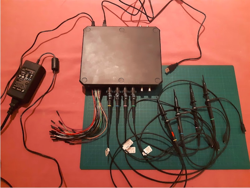
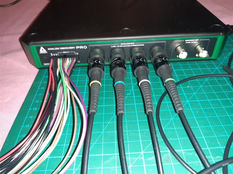
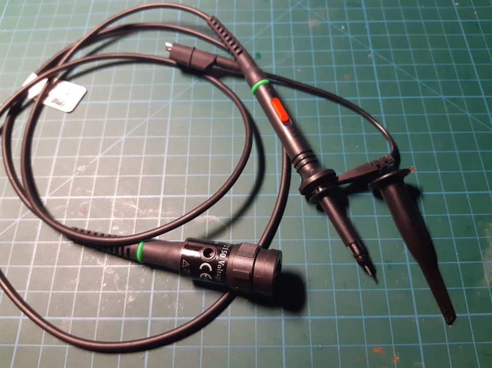
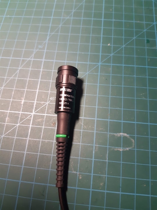
Trying to avoid wasting time I quickly went to the next point of my plan conducting “labs” from the tutorial.
But first of all I had to prepare my workshop installing WaveForms.
Software installation went smoothly without doubts with options to be selected etc. No issues,no incompatibility errors just idyll
In my application I declared to go through licensing and upgrade policy, extension modules if any (paid version free trials etc.) There is no subject as the WaveForms is an extended and powerful but absolutely free suite.
After review of available official software features, I wondered if something else is available, add-ons, etc.Apart from Waveforms SDK and Linux mode features (which give many development opportunities) nothing else is offered but also- IMHO isn’t necessary.
I promised to avoid pouring word but use examples depicted using photo/films documentation
Run the WaveForms
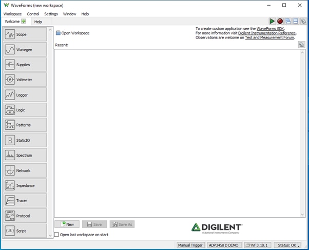
Select the oscilloscope
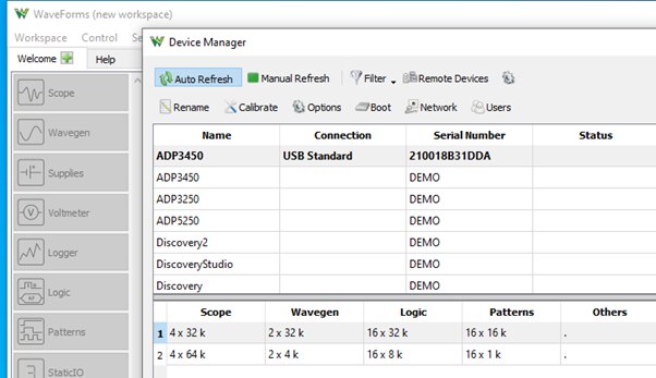
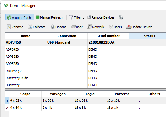
after selections details appear at bottom

Use help
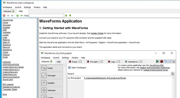
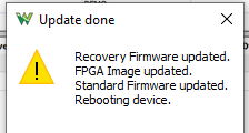
If the upgrade is available - let's run it
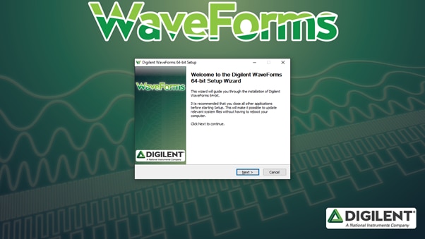
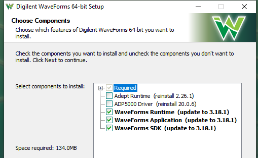
If available, we can also update of the device

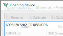
Perform the speed test

Now start the ordinary work
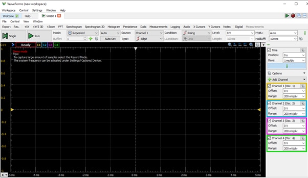
First of All - using oscilloscope screen
Using wave generators
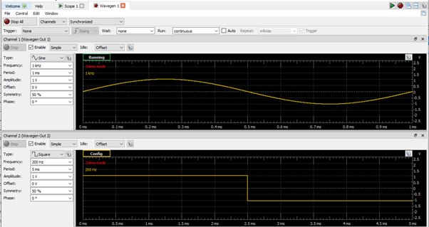
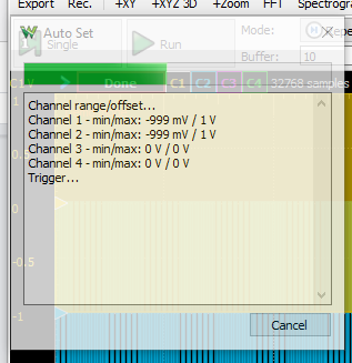
After connection oscilloscope probes to the GEnerator channels we can examine it
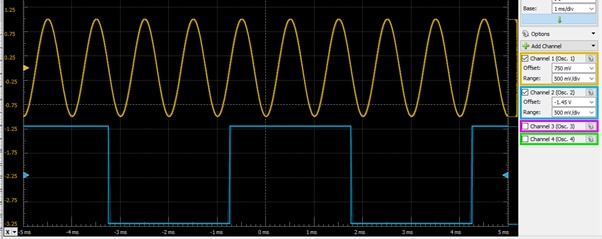
Going through “instruments”
Our device is 4 channel voltmeter

as well as digital supply source
that is used to configure a Digilent Test & Measurement Device's variable power supplies.

Testing logger - used to log analog voltage data over long periods of time
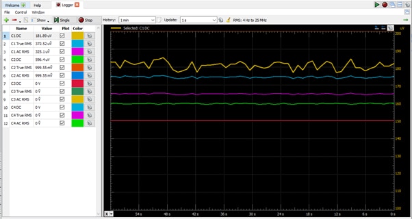
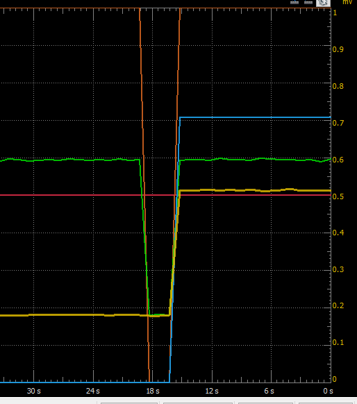
here is visualization of switch on “shock” signal
Pattern instrument in work

Digital Pattern Generators can be easily used to create digital signals simulating a circuit or device.
result viewed on Static I/O

used to visualize digital input/output channels through simulated buttons, LEDs, displays, and sliders.
I went through selected settings and oscilloscope functions
All are easy accessible and intuitive
i.e. modes:


mode: Shift 

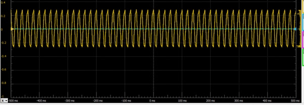
Basic measurements
Clock output of microcontroller
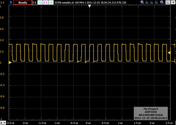
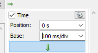
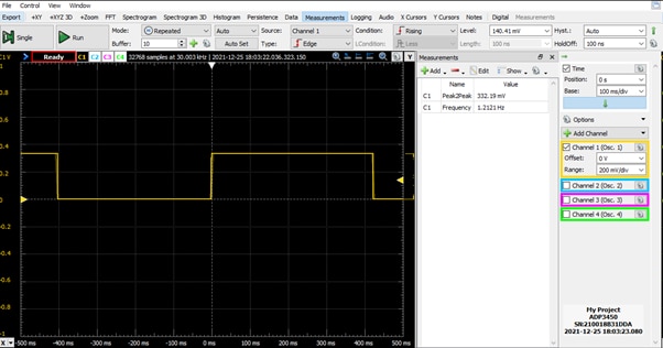
frequency measurement

Simple use of Wave GEN together with the SCOPE
first low frequency: 1kHz
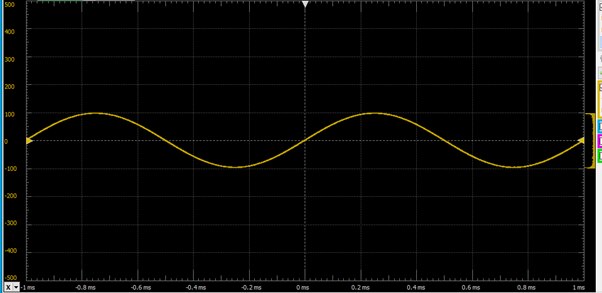
preview of FFT shape

Generator has limitation shouldn't be run above 5 MHz
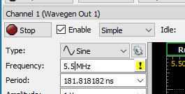
Let's set it on the boundary level 5MHz and view behaviour using scope

looks smouth
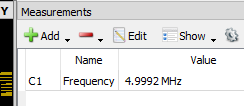 and acurate indeed
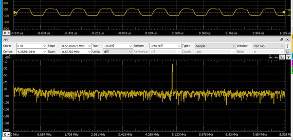
using FFT the frequency can be easily estimated
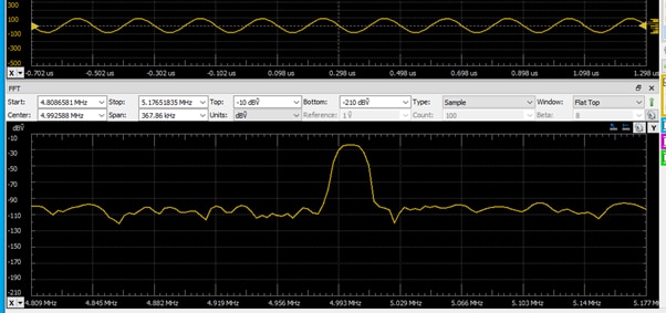
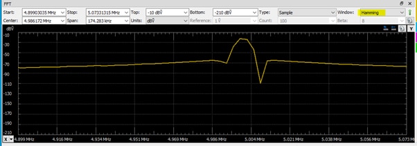
the spectrum view

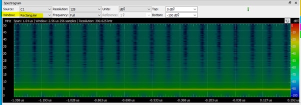

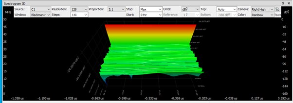
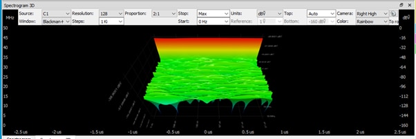
and 3D spectrum which is very handy tool for complicated signals
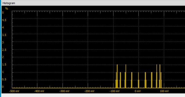
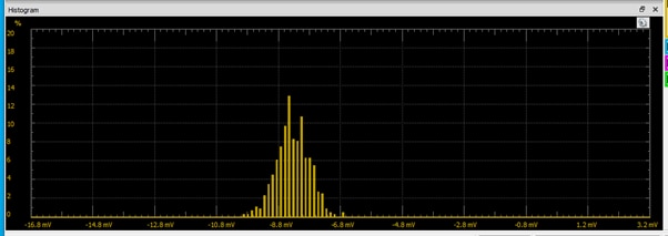
histogram shows some harmonics
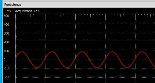
Using Spectrum Instrument for above signal measure
Spectrum Analyzers are used to view captured analog signals in the frequency domain
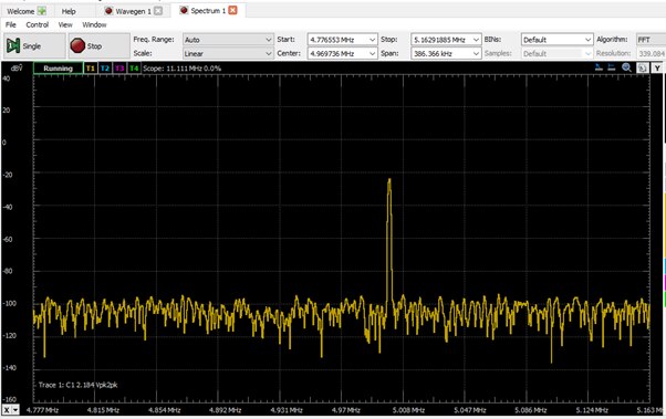
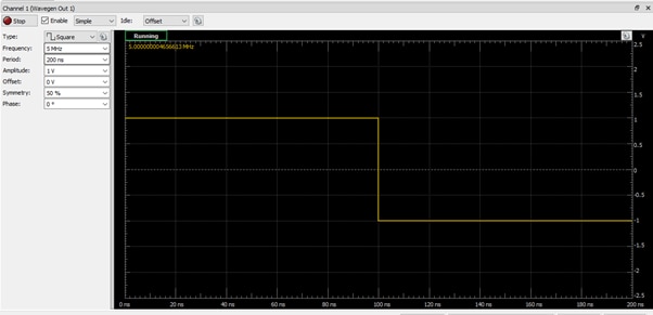
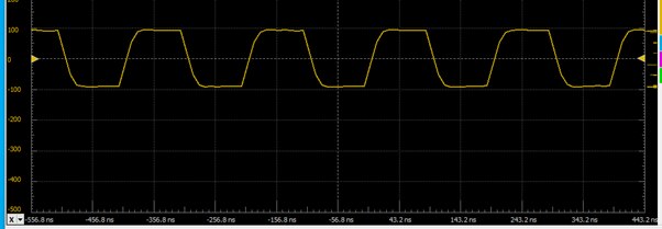
The square signalwith the same frequency 5MHz
in generator
on the scope screens
and triangle also 5MHz
 isn't as sharp
ramp signal

My experiments with Radio Frequency takes a (long) while
Some conclusions are depicted below
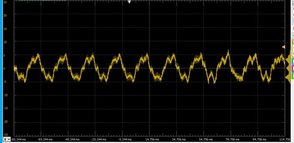
Deep into signal
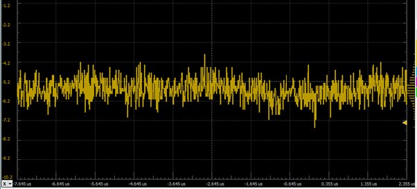
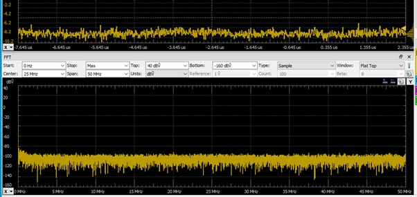
display the amplitude of the incoming signal vs. frequency by using Fast Fourier
Transform (FFT) calculations. The FFT function of oscilloscopes can be useful in identifying the fundamental
frequency,
Using zoom
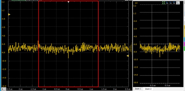
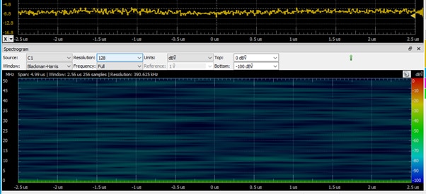
A spectrum analyzer is an instrument that displays the amplitude vs. frequency for input signals.
my patient was old CB equipment
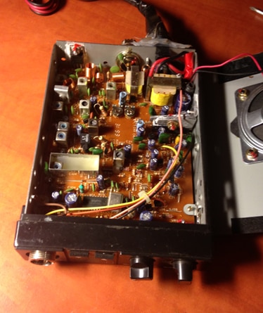
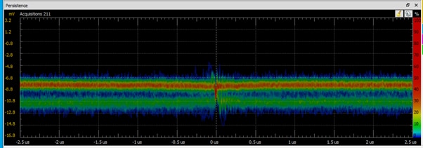
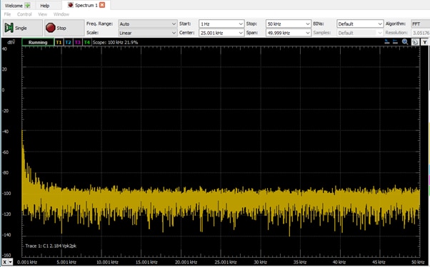
I must have missused oscilloscope as there is nothing special on spectrum view
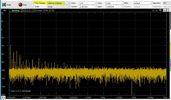
my attempts to find any charecteristic of waves
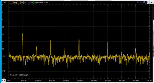
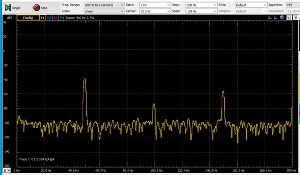
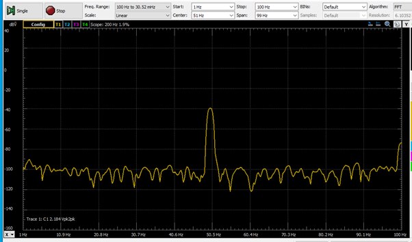
Change to logharitmic gives better view in that case
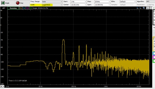
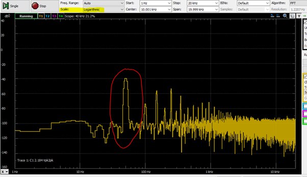
Next exercise
let's produce 50Hz noise
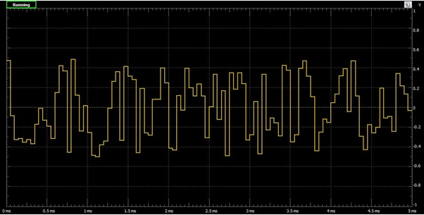
And view the signal from generator on handheld toy- scope
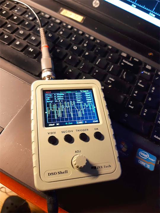
Looks quite similar and accurate
Experiments with external signals observation
"FADE" signal


Funny task – compare it with view on the old scope
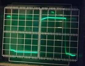
PWM signal
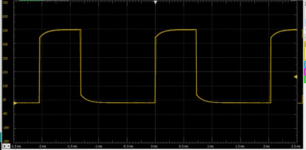
In different stages
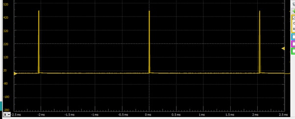
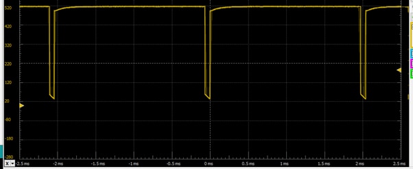
stepper motor control signals

SD card – digital signals on analogue inputs
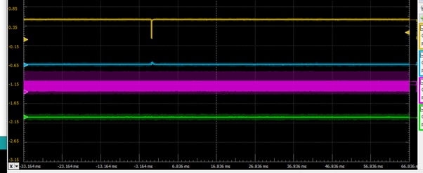
SPI

Using logic part of the device
Logic Analyzers are used to capture and view digital signals.
Protocol Analyzers are used to send, receive, and spy on transactions of different digital communication protocols.
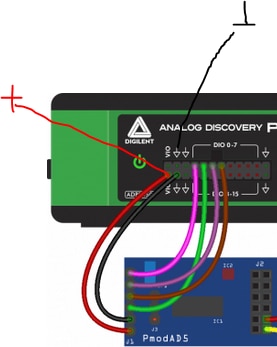
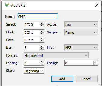

Analyzer catched the frame:

another view
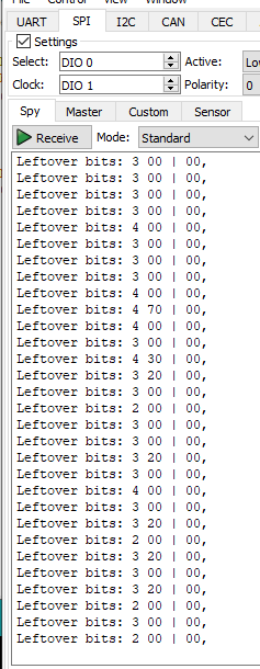
SPI MOSI

I2C

UART
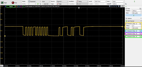
view on UART protocol using the scope
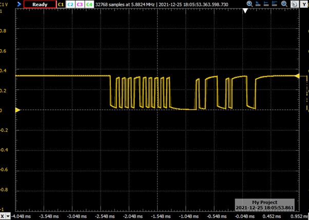
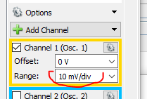
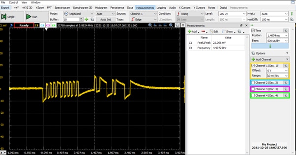
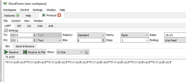
Above experiment helped to correct the circuit. ucontroller GPIOs were left without correct pullups.
After correction the protocol was recognized and easy readable

usage of logicsection to spy and read data
both RUN or SIMPLE gave the result

data: 0xAA; 0x55;0x00;0x1E; 0x1F; which are exactly what I wrote in uC code

UART - export to file
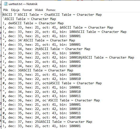
Using the Impedance Analyzer Instrument
Impedance Analyzers are used to measure a circuit-under-test's response to input signals of differing frequencies.
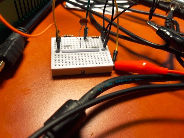
Below simple circuit for capacitor measurements

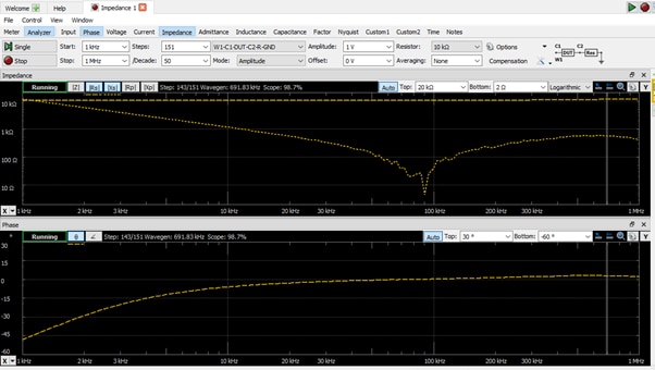
it was 20nF capacitor is measurement or element inaccurate ?
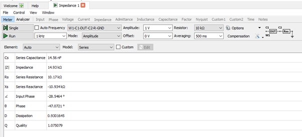
Next one was more precise
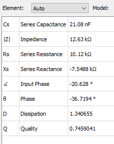
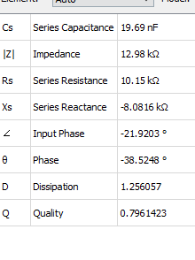


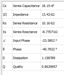 that one is marked as 22nF
a’m afraid I should change cap’s dealer.
And most challenging for me
TRACER (Curve Tracer) instrument
A semiconductor curve tracer (semiconductor parameter analyzer) is used to analyze the characteristics of discrete semiconductor devices such as diodes, transistors, and thyristors.It can be used to stimulate the device under test (DUT).
https://digilent.com/reference/test-and-measurement/guides/waveforms-curve-tracer
https://digilent.com/reference/test-and-measurement/transistor-tester-adapter/getting-started
I used 10 kΩ resistor on board for Rb and a 100 Ω resistor on board for Rc.
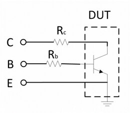

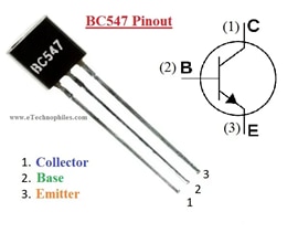
Results aren’t as expected
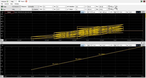
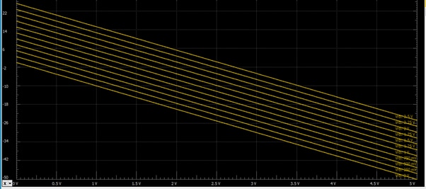
I confess Me - not oscilloscope failed the exercise.
Next attempt to get the transistor characteristic - using “manual” settings
first the generators:
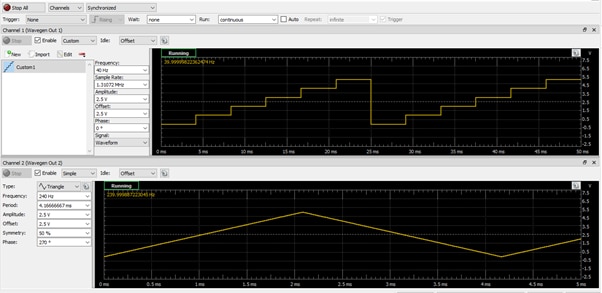
but after many fails I gave up.
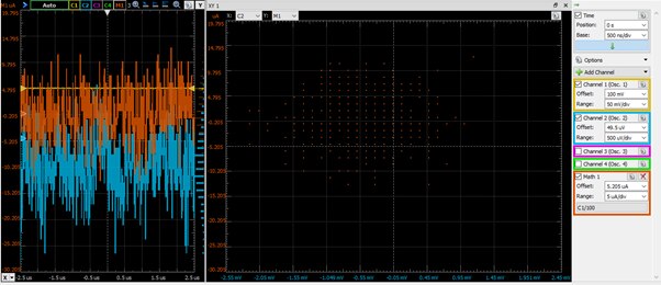
At that step I must end that stage and the report in general . Roadtest time ends.
Many exercises conducted, a lot of oscilloscope functions tested.
Nevertheless, even more remains to be assessed and used at work.
I can promise to continue in the blog.
I spent many hours and had a very good time exercising with the oscilloscope. Analog Discovery Pro exceeds the programm I realized thus my adventure doesn't end here.
Some doubts must be explained. Some homework done, new lessons learned or repeated.
I want to express in short words the main impression which is not easy task.
But one thing comes to mind and is obvious for me.
The set: Analog Discovery Pro together with WaveForms is a complex but extremely intuitive tool.
That is the main conclusion.
Another important thought concerns the scale of the device. In my opinion it can’t be compared very much with little brother Analog Discovery II.
I can’t bring ADPro in my pocket (at least the small bag is necessary)
But we can’t treat it as a disadvantage. Analog Discovery Pro focused on noble laboratory tools and should be compared in that group.
In my opinion it is perfect for hobbyists, students as well as professional engineers.