RoadTest: PAN9520 Wi-Fi Module Evaluation Board
Author: alfadar
Creation date:
Evaluation Type: Test Equipment
Did you receive all parts the manufacturer stated would be included in the package?: True
What other parts do you consider comparable to this product?: Arduino, ESP32
What were the biggest problems encountered?: 5V pin and I2C pins
Detailed Review:
PAN9520
ESP32-S2
I am a teacher who teaches students of the professional course in Electronics, Automation and Computers aged between 15/18 years.
The board test aims to verify the possibility of application in the various activities that we are used to implementing in the classroom.
The process will be applied as follows:
First of all mandatory documentation
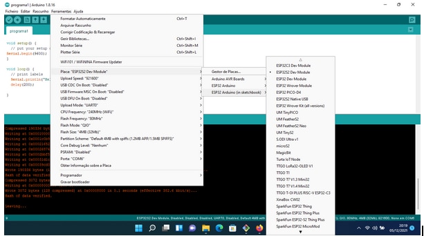
Software setup and installation process


Following the information provided by the PAN9520 support pdf, installation and configuration was simple and fast.
Quick bench-test
Quick introduction to the board
A set of small quick bench-tests were performed in order to compare with Arduino Uno using, port verification and wifi test.
First test was performed against Arduino Uno to check the speed of response: A simple comparison of answers with a board that we use regularly in the classroom
//programa Teste 1
#define targetBoard "esp32s2-rc4-20191025"
#define ideVersion "Arduino IDE v1.8.16"
#define analoguePin 5
#define digitalPin 11
#define ledPin 21

#define loopCount 50000   // Max 65535

void setup() {
  Serial.begin(115200);
  pinMode(ledPin,OUTPUT);
  digitalWrite(ledPin,LOW);

  pinMode(analoguePin,INPUT);
}

void loop() {
  unsigned long startTime;
  unsigned long totalTime;
  unsigned int x;
  int ar;

  Serial.print(F(targetBoard));
  Serial.print(F(" I/O Speed Tests Over "));
  Serial.print(loopCount, DEC);
  Serial.print(F(" Iterations. Compiled Using "));
  Serial.println(F(ideVersion));
  Serial.flush();
  delay(1000);

  // Digital Write
  pinMode(digitalPin,OUTPUT);
  digitalWrite(ledPin,HIGH);
  startTime = micros();
  for (x = 0; x < loopCount; x++){
    digitalWrite(digitalPin,HIGH);
    digitalWrite(digitalPin,LOW);
  }
  totalTime = micros() - startTime;
  digitalWrite(ledPin,LOW);
  Serial.print(F("Digital Pin Write Takes About "));
  //Serial.print(totalTime / 2);
  //Serial.print(F(" Microseconds And Each 'digitalWrite' Took About "));
  Serial.print((float)totalTime / (float)loopCount / 2.0, 4);
  Serial.println(F(" Microseconds."));
  Serial.flush();
  delay(1000);

  // Digital Read
  pinMode(digitalPin,INPUT);
  digitalWrite(ledPin,HIGH);
  startTime = micros();
  for (x = 0; x < loopCount; x++){
    ar = digitalRead(digitalPin);
  }
  totalTime = micros() - startTime;
  digitalWrite(ledPin,LOW);
  Serial.print(F("Digital Pin Read  Takes About "));
  Serial.print((float)totalTime / (float)loopCount, 4);
  Serial.println(F(" Microseconds."));
  Serial.flush();
  delay(1000);

  // Analogue
  digitalWrite(ledPin,HIGH);
  startTime = micros();
  for (x = 0; x < loopCount; x++){
      ar = analogRead(analoguePin);
  }
  totalTime = micros() - startTime;
  digitalWrite(ledPin,LOW);
  Serial.print(F("Analogue Pin Read Takes About "));
  //Serial.print(totalTime / 2);
  //Serial.print(F(" Microseconds And Each 'digitalWrite' Took About "));
  Serial.print((float)totalTime / (float)loopCount, 4);
  Serial.println(F(" Microseconds."));
  Serial.println();
  Serial.flush();
  delay(1000);
}
Test results
Teste 1: Pan9520, answers
esp32s2-rc4-20191025 I/O Speed Tests Over 50000 Iterations.
Compiled Using Arduino IDE v1.8.16
Digital Pin Write Takes About 0.1255 Microseconds.
Digital Pin Read  Takes About 0.1380 Microseconds.
Analogue Pin Read Takes About 62.5175 Microseconds.
 Teste 1: Arduino Uno, answers
Arduino UNO I/O Speed Tests Over 50000 Iterations.
Compiled Using Arduino IDE v1.8.16
Digital Pin Write Takes About 5.5329 Microseconds.
Digital Pin Read  Takes About 3.0808 Microseconds.
Analogue Pin Read Takes About 112.0019 Microseconds.
In conclusion: As we can see, the PAN9520 is a board that has, in all tested points, a better response than its comparative.
The next test tries to check the PAN9520 ports for better input/output recognition
//Programas Portas
void setup() {
  // put your setup code here, to run once:
  delay(500);
  Serial.begin(115200);
  delay(500);
  Serial.println("\n\n================================");
  Serial.printf("Chip Model: %s\n", ESP.getChipModel());
  Serial.println("================================");

#ifdef EXTERNAL_NUM_INTERRUPTS
  Serial.printf("EXTERNAL_NUM_INTERRUPTS = %d\n", EXTERNAL_NUM_INTERRUPTS);
#endif
#ifdef NUM_DIGITAL_PINS
  Serial.printf("NUM_DIGITAL_PINS = %d\n", NUM_DIGITAL_PINS);
#endif
#ifdef NUM_ANALOG_INPUTS
  Serial.printf("NUM_ANALOG_INPUTS = %d\n", NUM_ANALOG_INPUTS);
#endif
  Serial.println();
  Serial.printf("Default TX:   %d\n", TX);
  Serial.printf("Default RX:   %d\n", RX);
  Serial.println();
  Serial.printf("Default SDA:  %d\n", SDA);
  Serial.printf("Default SCL:  %d\n", SCL);
  Serial.println();
  Serial.printf("Default SS:   %d\n", SS);
  Serial.printf("Default MOSI: %d\n", MOSI);
  Serial.printf("Default MISO: %d\n", MISO);
  Serial.printf("Default SCK:  %d\n", SCK);
  Serial.println();
  Serial.printf("Default A0:   %d\n", A0);
  Serial.printf("Default A1:   %d\n", A1);
  Serial.printf("Default A2:   %d\n", A2);
  Serial.printf("Default A3:   %d\n", A3);
  Serial.printf("Default A4:   %d\n", A4);
  Serial.printf("Default A5:   %d\n", A5);
  Serial.println("================================");
}

void loop() {
  // put your main code here, to run repeatedly:

}
Results:
================================
Chip Model: ESP32-S2
================================
 EXTERNAL_NUM_INTERRUPTS = 46
 NUM_DIGITAL_PINS = 48
 NUM_ANALOG_INPUTS = 20
 Default TX:   43
 Default RX:   44
 Default SDA:  8
 Default SCL:  9
 Default SS:   34
 Default MOSI: 35
 Default MISO: 37
 Default SCK:  36
 Default A0:   1
 Default A1:   2
 Default A2:   3
 Default A3:   4
 Default A4:   5
 Default A5:   6
 ================================
The next test tries to check wifi: this networks is WPA, WPA2
Testing...
/Programa Wifi
/*
  Example from WiFi > WiFiScan
  Complete details at https://RandomNerdTutorials.com/esp32-useful-wi-fi-functions-arduino/
*/

#include "WiFi.h"

void setup() {
  Serial.begin(115200);

  // Set WiFi to station mode and disconnect from an AP if it was previously connected
  WiFi.mode(WIFI_STA);
  WiFi.disconnect();
  delay(100);

  Serial.println("Setup done");
}

void loop() {
  Serial.println("scan start");

  // WiFi.scanNetworks will return the number of networks found
  int n = WiFi.scanNetworks();
  Serial.println("scan done");
  if (n == 0) {
      Serial.println("no networks found");
  } else {
    Serial.print(n);
    Serial.println(" networks found");
    for (int i = 0; i < n; ++i) {
      // Print SSID and RSSI for each network found
      Serial.print(i + 1);
      Serial.print(": ");
      Serial.print(WiFi.SSID(i));
      Serial.print(" (");
      Serial.print(WiFi.RSSI(i));
      Serial.print(")");
      Serial.println((WiFi.encryptionType(i) == WIFI_AUTH_OPEN)?" ":"*");
      delay(10);
    }
  }
  Serial.println("");

  // Wait a bit before scanning again
  delay(5000);
}

results:
 scan start
 scan done
 4 networks found
 1: NOS-40D2 (-60)*
 2: NOS-40D2_ (-65)*
 3: MEO-9DA1D0 (-68)*
 4: MEO-WiFi (-69)
Application in small projects
After reading the user manual, the first work on the board was to use the SW and the LEDs of the board itself:

// Programa que testa Sw e o led (vermelho) da board
void setup() {
Serial.begin(9600);
//pinMode(21,OUTPUT);
pinMode(1, INPUT_PULLUP);
}

void loop() {
/*delay(1000);
Serial.println("pong");
digitalWrite(21,HIGH);
delay(1000);
digitalWrite(21,LOW);*/
if (digitalRead(1)!=1) {
  Serial.println("pong");
  }
}

in order to adapt to the GPIO and the result was excellent because it allows programming with input / output
using PULLUP concepts without the need to use electronic components just using a board.
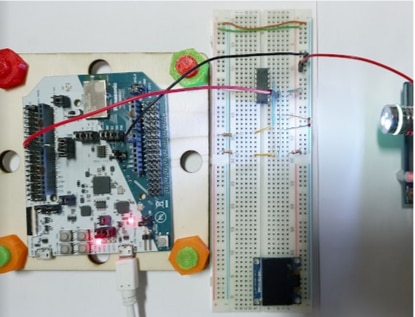
In the second project the idea is to use PAN9520 as data collection, we have ldr (controlled by LM339n)
that identifies the power cut of a leisure and sends an input to the PAN9520 and this returns the time the power cut was made.
We encountered some problems with the LM339n (LM) power supply and had to power the LM externally.
By the way, the feeling that was left was that the PAN9520 has to be powered by an external source, pc power may not be enough.
The first idea was to use an Oled I2C screen but we simply couldn't use it, it could be a result of using the 5v board power supply
or unluckily the sensor used could be having problems, but… !
//programa carros balão
int startPressed = 0;
int endPressed = 0;
int idleTime = 0;
int holdTime = 0;
int carros=0;
void setup()
{
  pinMode(10, INPUT);
  Serial.begin(9600);
}

void loop()
{
 if (digitalRead(10)!= HIGH){
   if (startPressed==0){

       startPressed = millis();
   }

  }
  else
  {
    if ( startPressed!=0){
     endPressed = millis();
     idleTime =  endPressed - startPressed ;
     Serial.println((String)"carro: " + (carros++) + (String(" Tempo:"))+idleTime );
    }
      startPressed=0;
      delay(100);
  }
}

The PAN 9520 allows the use in school projects to collect information without any problems
and with the advantage that the pins are connected using a jumper type.
Project using a dht22 sensor and web server

The main idea is to use the board as a web server and send information obtained from a dht22, humidity and temperature.
//web server e dht22
#include <WiFi.h>
#include <WiFiClient.h>
#include <WebServer.h>
#include <ESPmDNS.h>
#include "DHT.h"

#define DHTPIN 10
#define DHTTYPE DHT22
const char* ssid = "--------";
const char* password = "------------";
float h;
float t;
WebServer server(80);
DHT dht(DHTPIN, DHTTYPE);
const int led = 13;

void handleRoot() {
  digitalWrite(led, 1);
  String texto="<html><h1>server PAN</h1><p>Humidade " +String(dht.readHumidity())+ " %</p><p>Temperatura "+String(dht.readTemperature()) +"</p></html>";
  server.send(200, "text/html",texto);
  //server.send(200, "text/plain", String(dht.readHumidity()));
  digitalWrite(led, 0);
}

void handleNotFound() {
  digitalWrite(led, 1);
  String message = "File Not Found\n\n";
  message += "URI: ";
  message += server.uri();
  message += "\nMethod: ";
  message += (server.method() == HTTP_GET) ? "GET" : "POST";
  message += "\nArguments: ";
  message += server.args();
  message += "\n";
  for (uint8_t i = 0; i < server.args(); i++) {
    message += " " + server.argName(i) + ": " + server.arg(i) + "\n";
  }
  server.send(404, "text/plain", message);
  digitalWrite(led, 0);
}

void setup(void) {
  pinMode(led, OUTPUT);
  digitalWrite(led, 0);
  Serial.begin(115200);
  WiFi.mode(WIFI_STA);
  WiFi.begin(ssid, password);
  Serial.println("");

  // Wait for connection
  while (WiFi.status() != WL_CONNECTED) {
    delay(500);
    Serial.print(".");
  }
  Serial.println("");
  Serial.print("Connected to ");
  Serial.println(ssid);
  Serial.print("IP address: ");
  Serial.println(WiFi.localIP());

  if (MDNS.begin("esp32")) {
    Serial.println("MDNS responder started");
  }

  server.on("/", handleRoot);

  server.on("/inline", []() {
    server.send(200, "text/plain", "this works as well");
  });

  server.onNotFound(handleNotFound);

  server.begin();
  Serial.println("HTTP server started");
  dht.begin();
}

void loop(void) {
  delay(2000);
  server.handleClient();
  delay(2);//allow the cpu to switch to other tasks
}

The use of DHT22 type sensors was simple, we used Arduino current libraries for this type of sensor or houses such as Adafruit for their application.
Using the 3v pin was seamless and connectivity was fast and easy.

Conclusion
In conclusion the PAN9520 is totally suitable for school electronics projects and IOT project.
PAN9520 is a very fast card with wifi connectivity with 48 digital pins and 20 analog pins, with the jumper pin assumption, is an advantage.
It needs external power to use the 5v pin and we had a lot of difficulty accessing the I2C.