RoadTest: Microchip dsPIC33C Digital Power Starter Kit
Author: MARK2011
Creation date:
Evaluation Type: Development Boards & Tools
Did you receive all parts the manufacturer stated would be included in the package?: True
What other parts do you consider comparable to this product?: As a comparable solution apart from the older brother from Microchip - MPLAB STARTER KIT FOR DIGITAL POWER (DM330017-2) or dsPIC30F based DM300023 dsPICDEM kit - nothing particular comes to my mind. I don't know other digitally controlled SMPS kits. Well there is STEVAL-ISA172V2 2 kW fully digital AC-DC power supply (D-SMPS) evaluation board but it is only one function device. Without programming and development possibilities.
What were the biggest problems encountered?: The transport/ packing issue at the beginning but it can be neglected. The only doubt is that I realized the system isn't flexible enough. I hoped to modify firmware of chips and use some power management examples from Microchip. I couldn't cope. According to the first review of papers I was sure I will use that kit exploring PowerSmart Digital Control Library Designer as well as Microchip Power Board Visualizer. That also failed.
Detailed Review:
Microchip dsPIC33C Digital Power Starter Kit roadtest
Microchip - one of leading electronic manufacturers known for years, from microcontrollers is expanding the scope of its activities year by year.
Recently, it has been “spoiling” the environment of electronics and developers with more and more interesting development and educational kits.
And so, the kit for testing the use of dsPIC SMPS systems in energy converter systems has entered the roadtest program.
Thank you Microchip, thank you element14 for the proposal to test these solutions.
Following Microchip definition, dsPIC33C Digital Power Starter Kit demonstrate and helps to understand principle of Digital Signal Controller (DSC) - the integration a Microcontroller (16-bit MCU) with a Digital Signal Processor (DSP)
In our case benefits of DSCs are employed in Switch Mode Power Supply (SMPS) device. Switching regulator is employed here to efficiently convert the power but unlike popular SMPS solutions which are generally analog, our kit demonstrate idea of digitally controlled SMPS (D-SMPS)
The board is intended to show that digitally (DSC) controlled SMPS is even easier to introduce and control as analog.
If you need some theory: basics of “switchers”
My board uses dsPIC33CK256MP505 as the “heart” but is also supported by many other sophisticated components. details below.

Best description of the kit with all supported instructions and documents is available at:
https://microchip-pic-avr-examples.github.io/dpsk3-power-boost-voltage-mode-control/index.html
or directly on github site
https://github.com/microchip-pic-avr-examples/dpsk3-power-buck-voltage-mode-control
I need to emphasize that during my (to be honest - significantly prolonged) R-T I noticed the supporting content changes. Microchip still adds some new information or chapters.
Copying above information in that report is unnecessary thus I follow to next interesting part:
In the following film I gathered the most impressive pictures I remember from the beginning of my adventure with dsPIC33C Digital Power Starter Kit.
We encountered an unpleasant issue as one of the big capacitors appeared damaged after unpacking the board.
As shown in pictures the orange box is the perfect place for safe transportation of the board unless you put the supply unit with multistandard adapters.
In my opinion that crowd in the box caused the disaster.
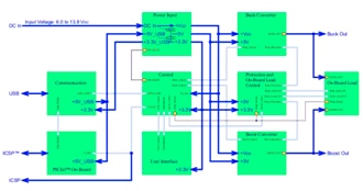
The dsPIC33C Digital Power Starter Kit SMPS consists of one DC/DC synchronous Buck Converter, one independent DC/DC Boost Converter, independent resistive loads, protection circuitry, USB/UART converter/bridge and on-board programmer/debugger circuitry.
Both power stages are controlled by the dsPIC33CK256MP505.
Loads and protection circuitry are controlled by an auxiliary PIC24FJ64GA004 microcontroller.
benefits of above solution is superbly described in

Digital Power Converter Basics using dsPIC33 Digital Signal Controllers
https://skills.microchip.com/digital-power-converter-basics-using-dspic33-digital-signal-controllers
That tutorial helps understand most nuances of DSCs implemented in digital power converters
The following film shows the parade of most important components of the board:
Introducing the main actors of the film :
dsPIC33CK256MP505 100 MIPS 16-bit dsPIC® DSC core with integrated DSP
belongs to modern dsPIC33CK family
https://www.microchip.com/en-us/product/dsPIC33CK256MP505
https://ww1.microchip.com/downloads/en/DeviceDoc/dsPIC33CK256MP508-Family-Data-Sheet-DS70005349J.pdf
PIC24FJ64GA004 PIC24 16-bit microcontroller, 64 KB Flash memory, 8 KB RAM
https://www.microchip.com/en-us/product/PIC24FJ64GA004
ATSAME70N21 32-bit ARM Cortex-M7 processor with Floating Point Unit
https://www.microchip.com/en-us/product/ATSAME70N21
USB2422 2-Port USB 2.0 Hi-Speed Hub Controller
https://ww1.microchip.com/downloads/en/devicedoc/00001726b.pdf
Simplified description of the equipment


Microchip provides us with all necessary papers and documentation. Most are available on the site above.
The starting point for explore, experiments or development is here:
https://www.microchip.com/en-us/development-tool/dm330017-3
dsPIC33C Digital Power Starter Kit User’s Guide

As the development environment to program debug and test PIC controllers, Microchip offers the brilliant solution : MPLAB… which word depicts it well? program suite? realm?
nevermind I love that tool.
Just like when discussing documentation also here I shouldn't copy MPLAB descriptions or tutorials
All is clearly given at Microchip’s sites and other related websites.
https://www.microchip.com/en-us/tools-resources
https://en.wikipedia.org/wiki/MPLAB


Brief view of MPLABX screen


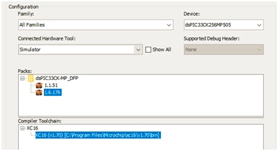
besides the main environment, many compilers, my favorite tool to support most PICs is MCC
Additional tool, precisely“Embedded Software Development Framework” is HARMONY
Initially I was not sure if Microchips HARMONY supports dsPIC33.I just forgot it is designed for 32bit PICs architecture So - unfortunately not but using MCC with libraries programing of all dsPIC33 family is more and more comfortable.
Other software intended to use with Microchip’s DSC solutions I planed to introduce:
Microchip Power Board Visualizer Supporting dsPIC33 DSCs Link
Software Library:
Microchip Power Board Visualizer Supporting dsPIC33 DSCs
https://www.microchip.com/en-us/software-library/power_board_visualizer

http://www.microchip.com/SWLibraryWeb/product.aspx?product=POWER_BOARD_VISUALIZER
wrong link?

Power Board Visualizer 1.0 Installation Guide
Power Board Visualizer User’s Guide
https://ww1.microchip.com/downloads/en/DeviceDoc/Power-Board-Visualizer-User-Guide-50003115.pdf
UG20181026O
https://microchip-pic-avr-tools.github.io/powersmart-dcld/#dcld_1
https://microchip-pic-avr-tools.github.io/powersmart-dcld/files/181026o_dcld_beta_user_guide.pdf


MPLAB® PowerSmart SDK Digital Control Library Designer Configuration Tool & Code Generator
https://microchip-pic-avr-tools.github.io/powersmart-dcld/

MPLAB® PowerSmart Digital Control Library Designer User’s Guide
https://microchip-pic-avr-tools.github.io/powersmart-dcld/files/181026o_dcld_beta_user_guide.pdf
https://microchip-pic-avr-tools.github.io/powersmart-dcld/#dcld_1
https://microchip-pic-avr-tools.github.io/powersmart-dcld/files/181026o_dcld_beta_user_guide.pdf
MPLAB PowerSmart SDK for Microchip dsPIC33® Digital Signal Controllers
Digital Control Library Designer (PS-DCLD)
And last not least : details of PICkit4 and its software
(it is onboard programmer in our kit)
MPLAB® PICkit 4 In-Circuit Debugger
https://www.microchip.com/en-us/development-tool/PG164140
Writing about documentation, tutorials and all useful supporting materials would consume time and space in that report. I need to cut it down here and describe my more practical activity.
The firmware lets the board operate in two main modes.
Loads – Can be configured for either Static mode or Dynamic mode.
If Dynamic mode is selected, a switching frequency can be configured in application SW.
The Buck Converter stage is rated for a maximum of 7.6W. However, the maximum
on-board configurable resistive load is 3.3W. The output voltage and output current
should remain within their Safe Operating Area (SOA) to avoid protection circuitry
tripping.
The Boost Converter stage is rated for a maximum power of 6W. However, the maximum
on-board configurable resistive load is 3W. The output voltage and output current
should remain within the Boost Converter Safe Operating Area (SOA) to avoid damage
to the board. The output voltage of the Boost Converter (Boost_Out) can be pro-
grammed from a 10V to 17.8V output, with a default programmed voltage of 15V
Basic modes of operation collected in the table below

I collected some waveforms of above described power modes from buck converter.
Review starts from static load with 10% P=0.45W these waveforms are mostly stable
You don't have permission to edit metadata of this video.
then with 100% (3W) on charts with larger step we see periodic (around 1s) distorsions
You don't have permission to edit metadata of this video.
Dynamic mode is overally stormy al all load levels.
You don't have permission to edit metadata of this video.
below - film with full review of all modes of buck converter
You don't have permission to edit metadata of this video.
below - film with full review of all modes of boost converter
You don't have permission to edit metadata of this video.
Faults when supplying inappropriate voltage or supply capacity is weak
Watch behavior of protection system when overheating
After playing with basic application, the time has come to check programming abilities, upload the main firmware, modify or adapt it. First I conducted steps from the guide.
dsPIC33C Digital Power Starter Kit Demo Code


Programming the chip - first check the programmer debugger compatibility


New task - export firmware (from dsPIC) using IPE


And the other way - uploading the firmware
There are two chips on the board to be programmed:
both dsPIC32 as well as support device: PIC24
dsPIC33C_Digital Power Starter Kit Demo Code.zip
view of folders used with MPLABX:


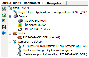
Following review of available simple application/code example from Microchip datasheets, GitHub resources etc

https://www.microchip.com/doclisting/TechDoc.aspx?type=codeexamples&productfamily=16-BIT

and on the github
https://github.com/microchip-pic-avr-solutions
One remark concerning use of supporting tools in programming
curiosity solutions very convenient when using some PICS as well dsPICs can’t be implemented in our module

There are several SMPS code examples available on the Microchip website. (www.microchip.com/SMPS)
https://www.microchip.com/en-us/solutions/power-management-and-conversion/intelligent-power
Solar MPPT Battery Charger for the Rural Electrification System
https://ww1.microchip.com/downloads/en/Appnotes/00002321A.pdf
16-bit PIC® and dsPIC® Microcontrollers
https://microchipdeveloper.com/16bit:start

Step-by-Step dsPIC33CH Programming Example dsPIC33CH128MP508S1
Step-by-Step dsPIC33CH Programming Example
dla dsPIC33CH128MP508 dual core
https://microchipdeveloper.com/16bit:ch-example

Project: Review communication channels
Basic aplications for dsPIC33 I made it simple using MCC


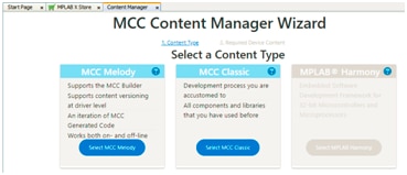
My UART project
Simple project to test programming capabilities of MPLAB/MCC and behave of dsPIC33




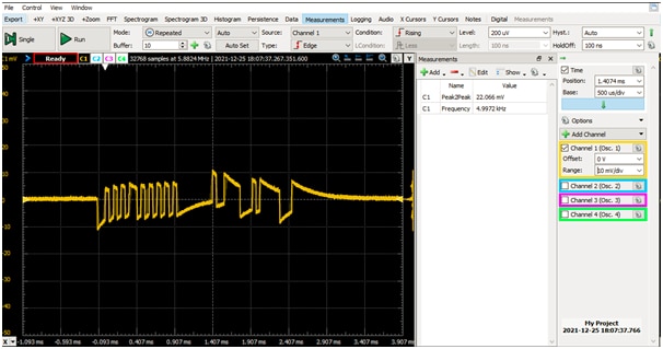

Many dsPIC projects are available in
dsPIC33C High-Resolution PWM Configuration I dspic33ck-power-pwm-complementary
https://github.com/microchip-pic-avr-examples/dspic33ck-power-pwm-complementary


download the example file


with project "DP Development Board demo project 1.0.0.0"

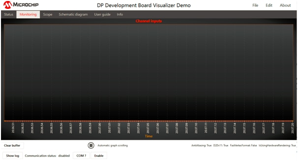


And one big doubt at the end of that stage…
despite promising declaration at the kit documentation/ manual site:

Our board isn’t supported by Microchip Power Board Visualizer
Thus I could play with it only theoretically but connections and management isn’t available.


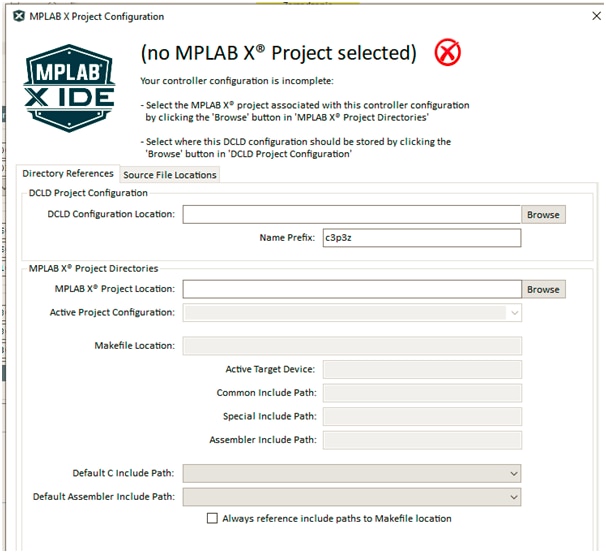


Above tool seems to be great support in development and debugging power applications based on dsPIC. Unfortunately although it is mentioned in our kit documentation, my dsPIC33C Digital Power Starter Kit (based on dsPIC33CK256MP505) can’t be supported. I considered which way to reprogram/ modify the code of both dsPIC and PIC24. But, at least with my skills I had to give up.
That is also general notice. Our board isn’t very flexible in the scope of modify applications and build DSC projects.
My plans to adapt some projects and create e.g. -
AC to DC | DC to DC | DC to AC | Wireless Charger and Receiver | Solar | Battery Management

- were too ambitious.
Nevertheless, the kit is doing a good job to introduce into the realm of digitally controlled SMPSs.
It should emphasize the degree of protection, ergonomy and overall elegance of the board.
Hoping that my report isn't chaotic very much and readable.
I'm open for discussion, every comment is welcome
Thank you
Marek