RoadTest: ROHM 8-Channel Multi-Rail DC/DC Converter Board
Author: shubham1998
Creation date:
Evaluation Type: Power Supplies
Did you receive all parts the manufacturer stated would be included in the package?: True
What other parts do you consider comparable to this product?: Other automotive-grade buck converters
What were the biggest problems encountered?: No major issues were encountered. But ROHM could provide users with the hard copy of documentation and jumpers with reference board.
Detailed Review:
The REFRPT001-EVK-001 reference design board is a power tree solution board developed by ROHM for infotainment devices such as automotive clusters and center information displays and for ECUs for ADAS application. This board consists of two Primary DC/DC Converter ICs (BD9P series), four Secondary DC/DC Converter ICs (BD9S series), one LDO, and two Power Supply monitoring ICs with self-diagnostic functions.
I this review I have evaluated electrical parameters of DC/DC converters like Output ripple with no load and maximum load as per REFRPT001-EVK-001 Application Note, Load Regulation, Line Regulation, Start-up waveform, Shutdown waveform, and Radiated Noise with current limit as per REFRPT001-EVK-001 EMC Test Report.
I received the evaluation board undamaged and double-boxed. The main box was having an antistatic bag in which evaluation board was placed, foam on both sides of the board, and a Precautions letter.
PCB is having test points for all DC/DC converters, silkscreen is small but readable, there are terminals for all DC/DC converters so connecting wires was easy and male headers for enable and mode functions.
The Application note and datasheets are very descriptive, so I am briefly describing here the functionality of the REFRPT001-EVK-001 reference design board.
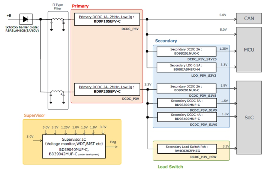
12V input is provided to the board at the BAT1 terminal. Between the input pins of Primary Stage DC/DC converters and BAT1 terminal, there is a 3A/60V Schottky barrier diode for protecting the circuit from wrong polarity and Pi filters which helps to block alternating current and removes ripple.
There are two Primary Stage DC/DC converters, BD9P105EFV-C for 5V and BD9P205EFV-C for 3.3V. The 5V Primary Stage DC/DC convertors then provide input to Secondary DC/DC Converter BD9S201NUX-C with the output of 1.25V and a BD00IA5MEFJ-M LDO regulator with output of 3.3V.
The 3.3V Primary Stage DC/DC converters provide input to Secondary DC/DC Converter BD9S201NUX-C with the output of 1.8V, Secondary DC/DC Converter BD9S300MUF-C with the output of 1.5V, and to Secondary DC/DC Converter BD9S400MUF-C with the output of 1V.
A BD39040MUF-C supervisor IC is also provided which monitors all eight output rails. The IC has quad power good, Watchdog timer, reset, and built-in self-test (BIST) functionality.
For the evaluation of the REFRPT001-EVK-001 reference design board, I used the following equipment: -

The board was powered with 12VDC. Only those DC/DC converters were enabled which were under test. Ripple was measured at output capacitors with tip and barrel method using TDS 684B Digital Oscilloscope.

Output ripple waveform of DCDC_P5V with no load

Output ripple waveform of DCDC_P5V with CC load of 1A

Output ripple waveform of DCDC_P5V_S1V25 with no load

Output ripple waveform of DCDC_P5V_S1V25 with CC load of 1.25 A
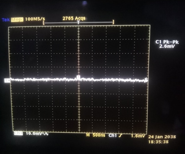
Output ripple waveform of LDO_P5V_S3V3 with no load

Output ripple waveform of LDO_P5V_S3V3 with CC load of 0.2 A

Output ripple waveform of DCDC_P3V with no load

Output ripple waveform of DCDC_P3V with CC load of 2 A

Output ripple waveform of DCDC_P3V_S1V0 with no load

Output ripple waveform of DCDC_P3V_S1V0 with CC load of 1.5 A
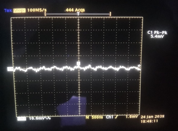
Output ripple waveform of DCDC_P3V_S1V5 with no load
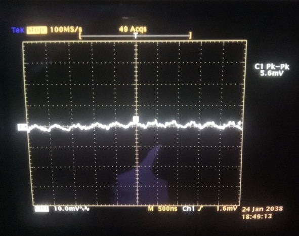
Output ripple waveform of DCDC_P3V_S1V5 with CC load of 1 A

Output ripple waveform of DCDC_P3V_S1V8 with no load

Output ripple waveform of DCDC_P3V_S1V8 with CC load of 0.5 A

Output ripple waveform of DCDC_P3V_PSW with no load

Output ripple waveform of DCDC_P3V_PSW with CC load of 0.5 A
Output Ripple Voltages for all DC/DC converters were under the limit and there was no significant change in the amplitude of ripple with load and no-load conditions.
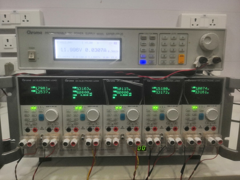
The board was powered with 12VDC. Only those DC/DC converters were enabled which were under test. Load was constantly increased, and Output Voltage was measured with Chroma DC ELECTRONIC LOAD.
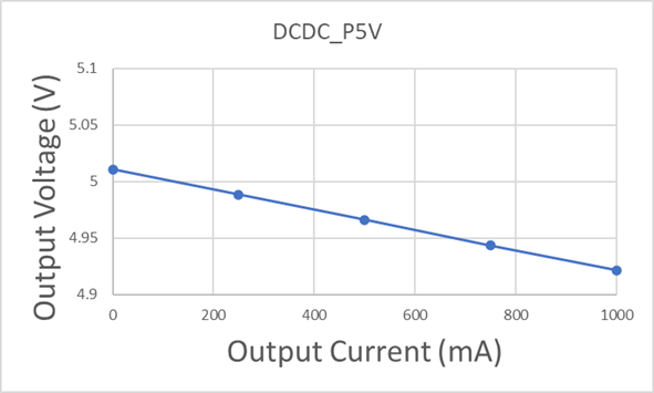
Load regulation of DCDC_P5V
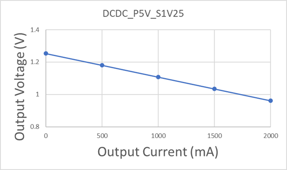
Load regulation of DCDC_P5V_S1V25

Load regulation of LDO_P5V_S3V3

Load regulation of DCDC_P3V

Load regulation of DCDC_P3V_S1V0

Load regulation of DCDC_P3V_S1V5

Load regulation of DCDC_P3V_S1V8

Load regulation of DCDC_P3V_PSW
Output Voltages for different loads were measured and for all Buck converters results are within limit except for DCDC_P3C_1V0 where Voltage was dropped to almost half at full load.
Please note that in Application Note LEDs and supervisor ICs are removed from the board while doing this test. So, both the data are not comparable.

The board was powered with 12VDC. Only those DC/DC converters were enabled which were under test. Input Voltage was constantly increased with Chroma DC Power Supply, and Output Voltage was measured with Chroma DC ELECTRONIC LOAD.

Line regulation of DCDC_P5V

Line regulation of DCDC_P3V
Output Voltages for different input voltages were measured and for all Buck converters results are within the limit.
Please note that in Application Note LEDs and supervisor ICs are removed from the board while doing this test. So, both the data are not comparable.

The board was powered with 12VDC. Only those DC/DC converters were enabled which were under test. The waveform was measured at TPs with the help of TDS 684B Digital Oscilloscope.

DCDC_P5V start-up waveform

DCDC_P5V_S1V25 start-up waveform
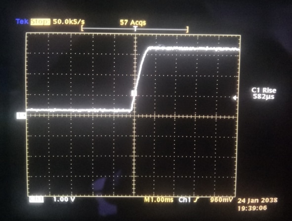
LDO_P5V_S3V3 start-up waveform

DCDC_P3V start-up waveform

DCDC_P3V_S1V0 start-up waveform

DCDC_P3V_S1V5 start-up waveform

DCDC_P3V_S1V8 start-up waveform

DCDC_P3V_PSW start-up waveform
Rise time for all Buck converters was measured and results are within the limit. The waveforms observed are without overshoot and are almost similar to REFRPT001-EVK-001 Application Note’s Start-up Waveforms.
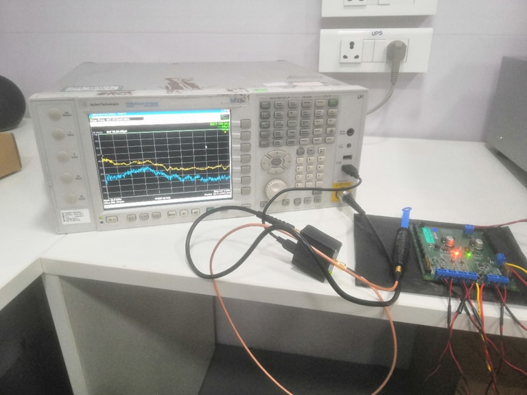
The board was powered with 12VDC. All DC/DC converters were enabled and were loaded according to the Measurement Conditions provided below. Result was measured with the help of the H10 EMC near field probe and MXA N9020A Signal Analyzer.
Note: This test was performed in an RF Chamber.


Radiated noise emission of REFRPT001-EVK-001
No significant peak was observed in the band of 30MHz to 1GHz.
Please note that in the REFRPT001-EVK-001 EMC test report a dedicated anechoic chamber is used for testing purposes. So, both data are not comparable.