RoadTest: METCAL GT120-HP-T6 Soldering Station
Author: amgalbu
Creation date:
Evaluation Type: Workshop Tools
Did you receive all parts the manufacturer stated would be included in the package?: True
What other parts do you consider comparable to this product?: There are no other soldering station using inductive heating with temperature control. In the same market segment, the product is comparable with JBC compact stations and ERSA i-Con product series
What were the biggest problems encountered?: There are no problem to report
Detailed Review:
Thanks to Element14, I have the opportunity to test the Metcal GT120-HP-T6 soldering station
The Metcal GT serie of soldering stations feature an inductive heating technology. In inductive heating, also called direct heating, an alternating current flowing through a precise coil generates a magnetic field. Placing an object (tip) within the field induces eddy currents which will create heat. Heat is produced where and only where these eddy currents flow. Customizing chemical composition alloy and optimizing the frequency allows the eddy current to flow to the outer surface resulting in less skin depth for instantaneous response
With resistive technology, heat is created from the heater coil, then conducted to the tip. Resistive heating has higher thermal resistance and therefore offers lower thermal performance than inductive heating
In this roadtest, I will try to evaluate whether the advantages offered by this technology can be appreciated in daily use and whether the GT120 soldering station worth its money
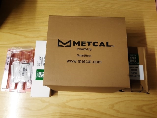
1. Unboxing
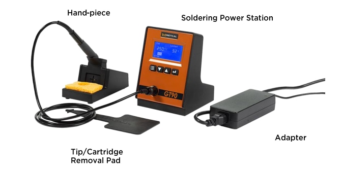
The kit shipped for this roadtest includes the following items
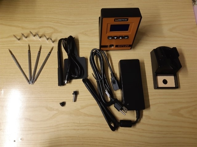
2. Kit components
2.1 The cradle
The cradle is very stable. It's heavy enough to provide a firm place to put the handle. The plastic feet below the base are "grippy" enough to make almost impossible to accidentally pull the base around the workbench.The cradle also include an handy place for the tip cleaner. Very useful the possibility to remove the tray form an easier removal of welding residuals.
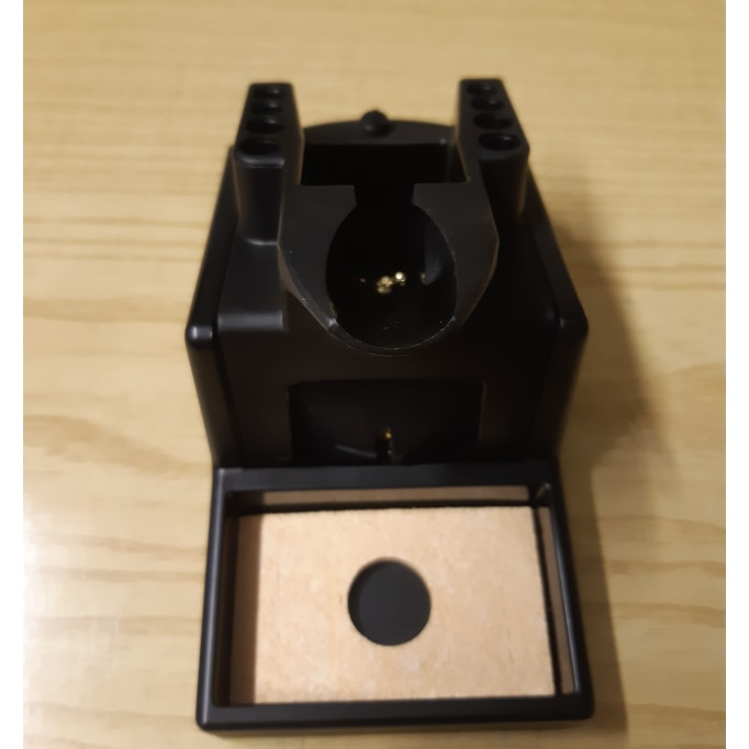
Fig.1 - The cradle
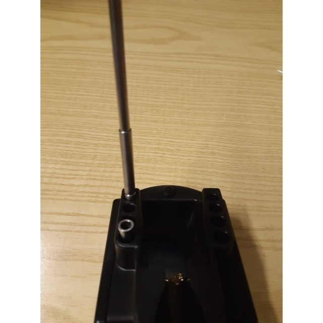
Fig. 2 - Tip holders
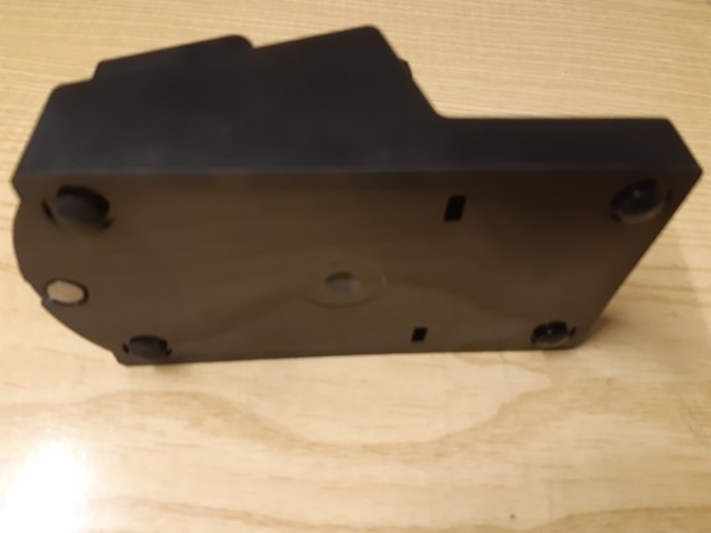
Fig. 3 - Bottom rubber feet
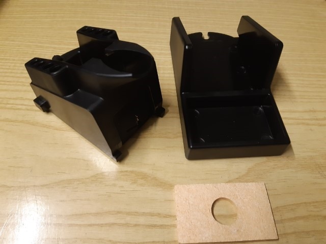
Fig. 4 - The cradle disassembled
2.2 The soldering station
The soldering station comes with a very solid metallic case, colored in black and orange. On the front panel, there are an LCD display and four buttons to navigate through the menu options. By default, the display shows the following information

Finally, on the front there is also a 4-pins round connector for the handle
On the back, there are the power switch (the size of which is well studied to be easily operated) and a USB port for the firmware updates
The menu provides several options. The most notable are
Another more advanced function is the temperature offset calibration, to get the best performances of the cartridges
Here is the menu navigation tree with all the available options

I really appreciated the fact that the power section is not included in the base station. As a matter of fact, there is an external power supply, which is apparently a standard power brick the takes the mains AC current and converts to 48V DC current. This solution has the advantage to make the base station smaller and lighter, and probably to keep the overall product cost down. By the way, the power supply is a high-quality item certified for medical use, so the decision to use an off-the-shelf power supply instead of developing a custom power section integrated in the soldering station looks quite good
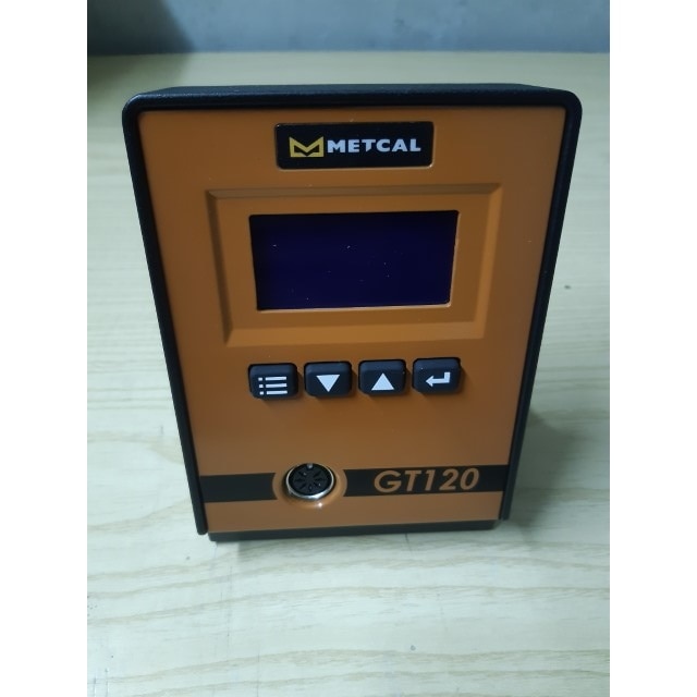
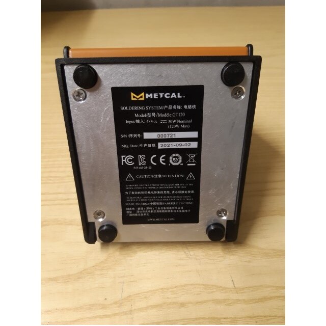
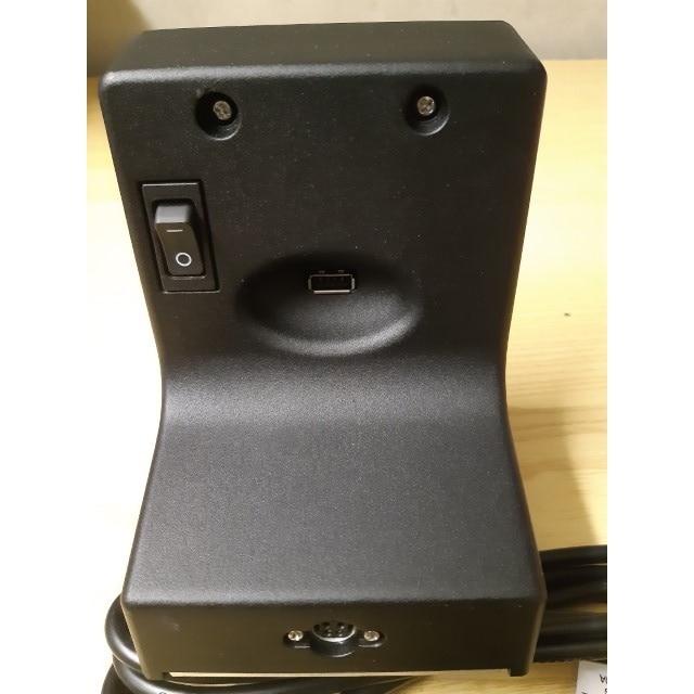
Fig. 5 - Front, bottom and back view of the soldering station
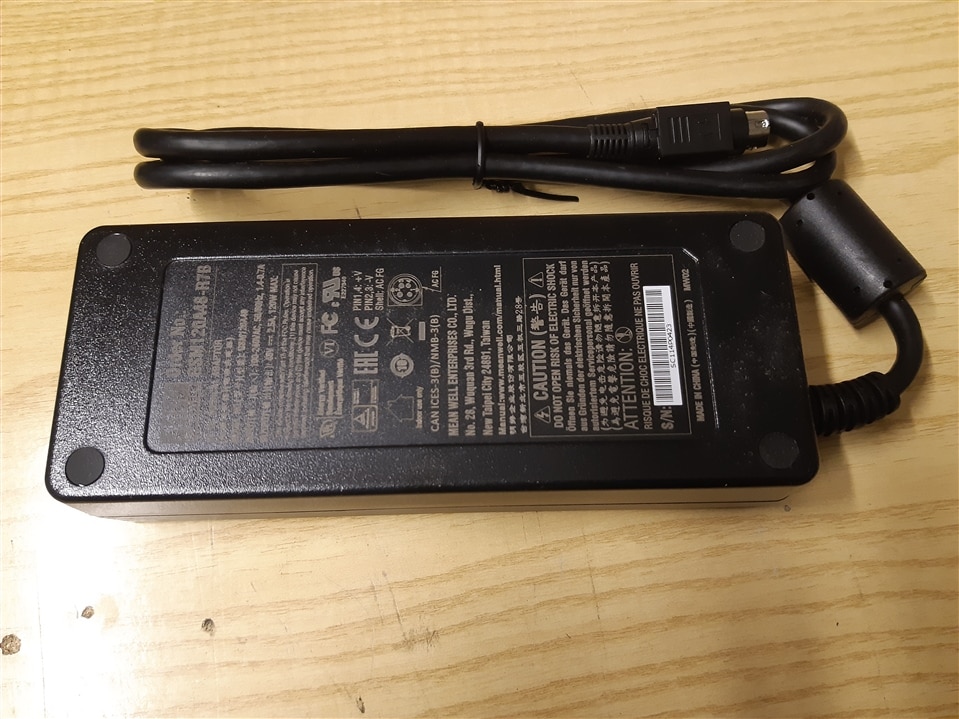
Fig. 6 - The power brick
2.3 Hand-piece
The hand-piece is quite thick. Someone may not like this from an ergonomic point of view. From my perspective, I like the feeling of the rubber the grip area of the hand-piece is covered with and the size is adequate for most of the uses. I also appreciated the presence of a mechanical lock on the connector, that makes any accidental disconnection of the cable basically impossible
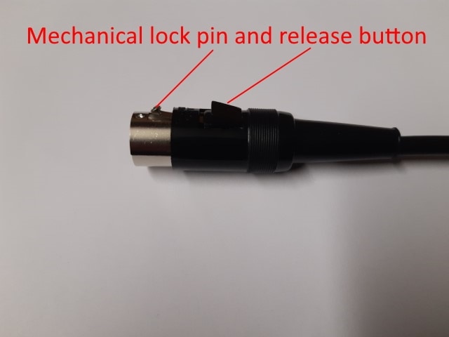
Fig. 7 - The hand-piece connector with the mechanical lock
2.4 Cartridges
The GT120-HP-T6 can use two different kind of cartridges


The first solution provides a cheap way to use different tips, but with some performance degradations because of the losses on the contact surface between the cartridge and the tip. The second solution provides optimal performances at a higher cost because you have to buy the whole cartridge if you want to use different soldering tips
The kit for this roadtest includes the following cartridges and tips
| Part number | Description | |
| GT-HC-T6 | T6 Heater cartridge |  |
| GTC-CH0010S | Chisel, 1.0 x 10.0 mm |  |
| GTC-CN1505A | Sharp, 0.5 x 15.0 mm |  |
| GTC-CH0050S | Chisel, 5.0 x 10.0 mm |  |
| GT6-CH0025P | Power, 2,5 x 6 mm |  |
| GT6-KN0050P | 5.0 x 16.0 mm |  |
| GT6-CN1505R | Conical, Bent, Reach |  |
| GT6-CH0010S | Chisel 1.0 x 10.0 mm | 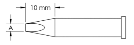 |
| GT6-CH0050S | Chisel 5.0 x 10.0 mm | 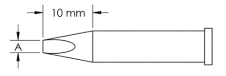 |
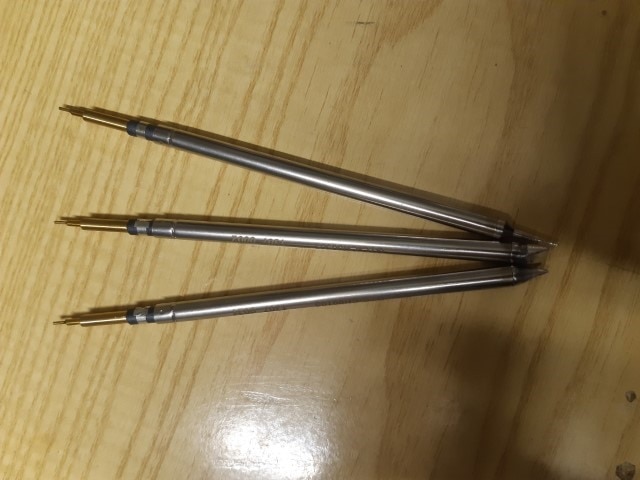
Fig. 8 - Standard cartridges
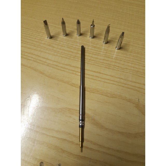
Fig. 9 - Heater cartridge and tips
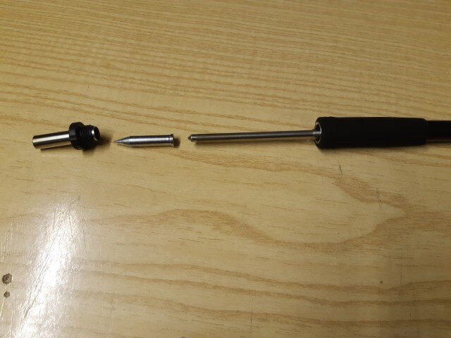
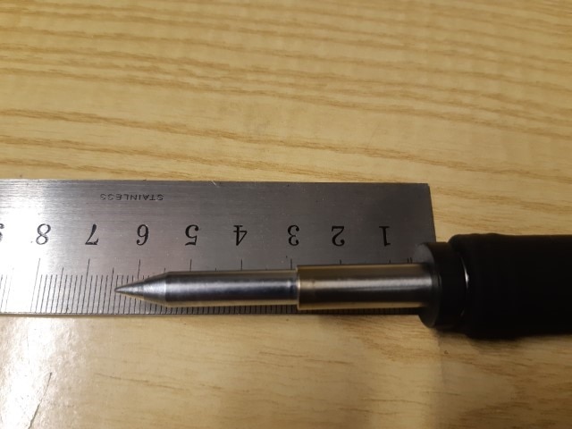
Fig. 10 - Assembling the heater cartridge and final tip length
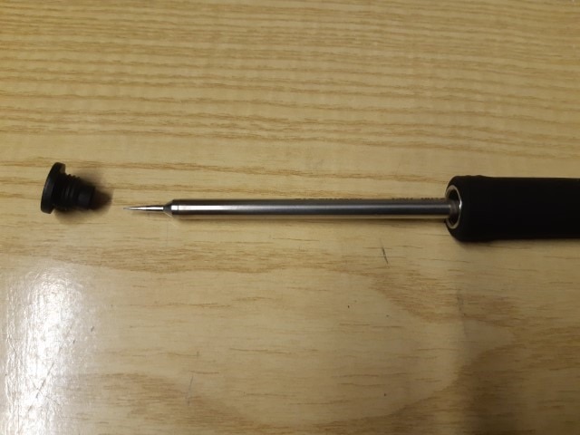
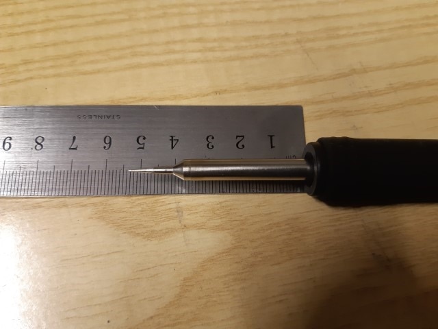
Fig. 11 - Assembling the standard cartridge and final tip length - about 1 cm shorter
3. Soldering test
I made some tests to check how the soldering station behaves in different conditions
3.1 Warmup time
One of the notable benefits of the inductive heating is the reduced warmup time. I tested the time it takes for the tip to reach the working temperature from a "cold" condition. I measured about 8 second to go from 20 °C to 400 °C
3.2 Breadboard
Here is a video that shows the soldering station being used for normal tasks, like soldering on a breadboard.
Results are good. I was really impressed by how the control logic is able to immediately detect the tin being posed on the soldering tip. In the same moment you place the tin on the soldering tip, you can see that the output level increases of a few percent. The hand-piece can be easily maneuvered. My impression is that the standard cartridge are more precise and easy to use, probably because the cartridge is shorter and, as a consequence, the tip is closer to the grip. However, if you look at the soldering, I have the feeling that there are no tangible differences between the heater cartridge + tip and the standard cartridge, so in my opinion the former is a viable and cheap solution for almost every laboratory or production environment.
3.3 High thermal mass
To test the reactivity of the temperature control algorithm, I tried to put some tin on a battery. This test aims to see how the control logic can detect a peak in requested power, and adapt output power accordingly.
The result looks quite good. Tin started flowing very quickly, and demonstrates that power control logic works as it should. The standard cartridges react faster: I see the tin flowing almost immediately on the soldering area, whereas the heather cartridges take a couple of seconds. During these tests, output level went as high as 50%
3.4 Temperature control
Another test that aims to evaluate the reactivity of the temperature control algorithm, is to let the tip temperature drop suddenly and see how the soldering station react. I used a wet sponge to make the tip temperature drop. Here is a video that shows how the output power changes to compensate the temperature drop
The PID worked as expected, compensating very quickly for temperature drop with a limited overshooting
4. Tear down
Let's have a look inside the soldering station.
I started removing the bottom cover, which discloses a couple of quite large inductors (after all, this is an inductive soldering station...)
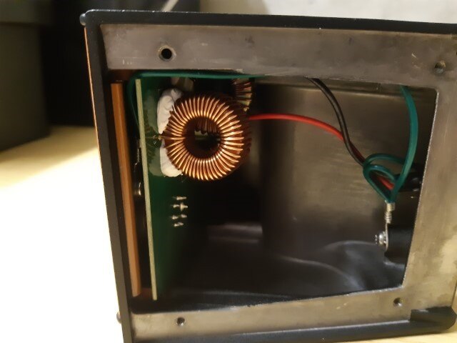
Fig. 12 - Soldering station with the bottom panel removed
The front cover can then be removed to disclose the front of the control board, which features a Microchip microcontroller. Apart from the microcontroller, there are few components on the board: a couple of LTC6088 low-noise low-offset rail-to-rail op amps (probably for measuring the tip temperature), a MOSFET (probably to drive inductors at the right frequency) and a step-down converter to power the electronics. The board design is neat, except for the display that, after removing the front cover, hangs dangerously
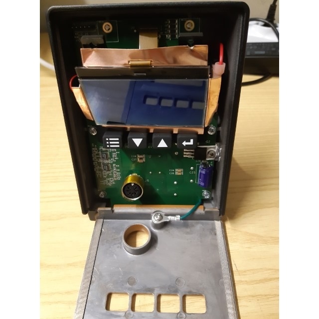
Fig. 13 - The soldering station with the front panel removed
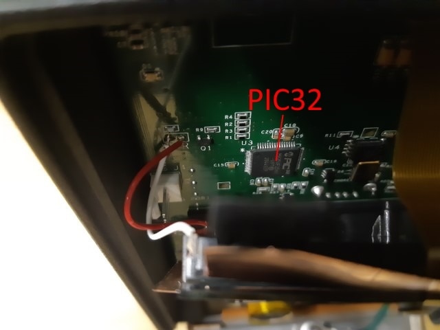
Fig. 14 - The PIC32 microcontroller
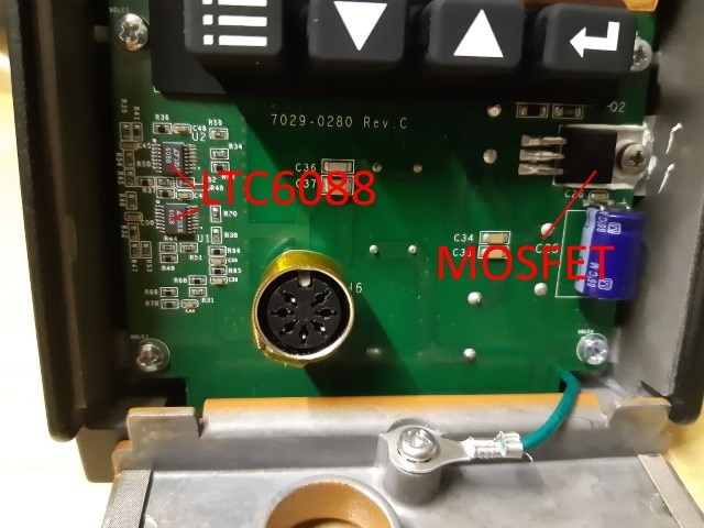
Fig. 15 - Some other important components
5. Conclusions
I've been using this soldering station for about one month, mostly for my electronic projects. You just need to set temperature between 330 and 350 degrees and you can do everything you need with no interventions. You need to set an higher temperature only when soldering components with high thermal mass. I noticed that you just need to set temperature a little bit higher (10-20 degrees) when using heater cartridges compared to when you use standard cartridges, probably because of thermal losses in the contact area between the cartridge and the tip.
I had some doubt about how practical it was to replace standard cartridges during work. Actually, it was quite simple: you can use the removal pad to pull out the cartridge by grabbing it from the tip (which is obviously very hot), then you can grab the cartridge from the body (which is almost cold, thanks to inductive technology) and place it in one of the slots in the cradle
Overall performances are very good, thermal power flows through the tip to adapt to the different working conditions. Manufacturing quality of the product is very good as well, especially the case of the soldering station is very robust and can survive the most heavy duties in a production environment.
The price is quite high, but it is proportionate to the overall quality of the product.
| Product performed to expectations | 5 stars | The product has been built with high quality standards. Software manages inductive heating to provide both a rapid warm-up and a stable temperature |
| Specifications were sufficient to design with | 5 stars | Metcal website provides plenty of documentation and white papers for a professional use of the soldering station |
| Demo software was of good quality | Does not apply to this roadtest | |
| Product was easy to ease | 4 stars | Connecting power supply and hand-piece is quite easy, probably a printed user manual with some details about how to assembly cartridges would be great. However, a complete user manual is available for download |
| Support material were available | 5 stars | As I said, Metcal website provides plenty of documentation and white papers for a professional use of the soldering station |
| The price to performance ratio was good | 4 stars | The GT120 soldering station cost $617 plus $36-$50 for a standard cartridge or $78 for a heater cartridge and another $30 at least for the tip. For sure, this is not cheap from a maker point of view. However, considering the quality of the construction, the performances and the unique technology implemented in this soldering station, the price is absolutely reasonable for use in a production environment |