RoadTest: PI BridgeSwitch Motor Drivers w/ Raspberry Pi Pico
Author: federicoma
Creation date:
Evaluation Type: Development Boards & Tools
Did you receive all parts the manufacturer stated would be included in the package?: True
What other parts do you consider comparable to this product?: don't know any
What were the biggest problems encountered?: To write the firmware for sensor-less control of the fan motor from the scratch. A ready to use firmware, or at least, some pieces of working code should be helpful.
Detailed Review:
First off all, I would like to thank Power Integration and element14 for the opportunity to evaluate the “PI BridgeSwitch Motor Drivers”. I would like to thank the community people for the idea sharing, troubleshooting, brainstorming message. A special thanks to jc2048 for the great value of the comment to my blog post. This is my first roadtest.
Summary and Conclusion
This was a very fun road test evaluation, my main interest is to understand if the PI BridgeSwitch can work without a heat sink, for my future projects.
Removing the heat sink is a very good cost saving solution for small inverter project, so it’s a very big opportunity to consider the PI BridgeSwitch solution.
Pros
• high overhall quality and reliability
• many integrated features
• pin to pin model with a higher current capability let you increase the board thermal performance just easy.
Cons
• difficult to use the current reading feature iPH
• difficult to use the comunication feature
Wish List
• Add some demo firmware to be downloaded to the Raspberry
• Share at least some piece of source code from the application notes AN-87.
Useful Document Links
https://www.power.com/products/bridgeswitch/bridgeswitch
https://www.power.com/design-support/application-notes/an-87-bridgeswitch-single-phase-bldc-motor-drive
https://www.power.com/design-support/design-examples/rdr-872-70-w-single-phase-inverter-using-bridgeswitch-fan-application
https://www.power.com/design-support/design-examples/rdr-873-30-w-single-phase-inverter-using-bridgeswitch-motor-driver
NOTE: Logging in to the respective websites may be required to access some of the documents.
Part 0 – A little bit of unboxing
The 13th of December 2021 I received the UPS packet for the roadtest, here you are a very fast unboxing of the board. The PI BridgeSwitch reference design kits looks like very well in their nice packet, very nice boxing, no damage problem possible because the multiball plastic cover.
The Raspberry comes into a plastic bag, and the fan coil comes in a multiball protection:
Part I – What is the PI BridgeSwitch?
Before diving into my actual roadtest of the PI BridgeSwitch, let’s take a look at what they are: two high-voltage N-channel power “FREDFETs” with low and high-side drivers in a single small-outline package.
You just need to pilot the BridgeSwitch with 2 signals, coming for example from the raspberry Pi, or from your MCU:
- INH to switch on the upper fredfet,
- INL for the lower one.
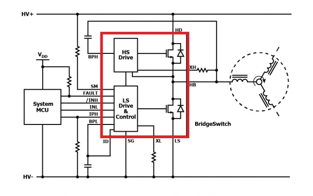
The shape of the case favor the high current connection, and following the device data sheet it’s possible to design a PCB routing for the correct an efficient heat dissipation. My advice is to read carefully the application note (just follow the useful document Links on top of the page) to get a good starting point for the evaluation of the device.
Part II – My roadtest project:
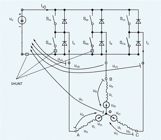
This is how I’m going to test the board: since I’m not able to write a motor control firmware from the scratch, for a BLDC motor, I’m going to use an old (but still working) inverter laying in my desktop from a while. This old inverter can perform a field oriented control to a 3 phase a PMSM, using sensorless control technique.
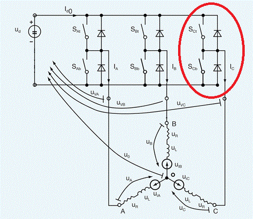
The inverter is a 3 legs, and in 2 of the legs there’s a shunt for the current reading. That’s because the firmware use the formula Ia+Ib+Ic=0 and calculate Ic from Ia and Ib. The idea is to replace the 3rd leg with one of the BridgeSwitch legs. Only one leg is possible, because only one miss the shunt.
Part III – Setting up the hardware, let’s hack the board:
This is the connection list for both the inverter:
|
RDR-872 70W inverter |
My inverter |
| TP1 | Vbus |
| TP2 | GND |
| J3(4) | INL_U micro pin |
| J3(5) | INH_U micro pin |
| J3(6) | GND |
| J3(10) | GND |
| J3(12) | 16V from flyback |
|
RDR-873 30W inverter |
My inverter |
| T1 | Vbus |
| T2 | GND |
| J2(4) | INL_U micro pin |
| J2(5) | INH_U micro pin |
| J2(6) | GND |
| J3(1) | 16V from flyback |
| J3(2) | GND |
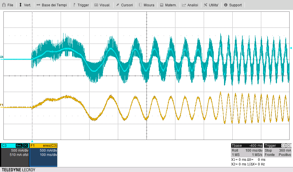
RDR-873 30W inverter startup and regimePart IV – My board measure:
The modified inverter can spin the motor, wonderfull !!!
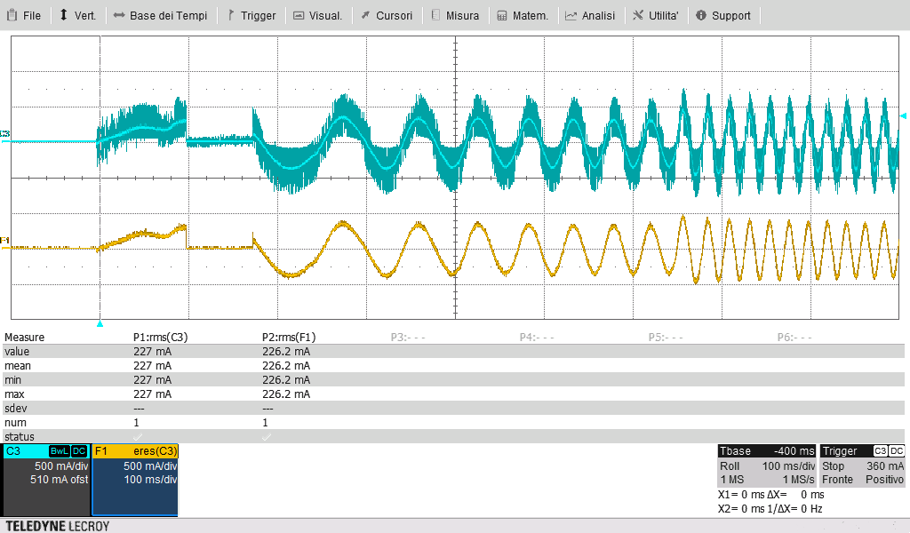
The current flowing through the Pi BridgeSwitch is 177mA rms.
The current is a little bit higher for the startup, since it’s a sensorless, but very soon it become 177mA, without reaching the max current limit (0,7A and 1,5A)
The blue track is the raw current measure coming from a current clamp, the yellow track is a filtered result of the current reading
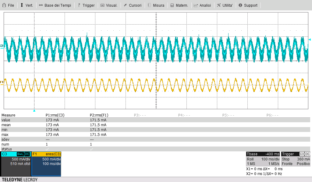
RDR-872 70W inverter startup and regime
Part V – PCB heat flow measure.
Since I get 177mArms flowing, I waited an hour to measure the final temperature of the bridge switch on both the demoboard.
This is usefull to understand the rdson value importance of the bridgeswitch. Let's analyse this result
|
RDR-873 30W inverter |
RDR-872 70W inverter |
|
|
Pi Bridge switch |
BRD1260C |
BRD1261C |
|
Rds On |
6.84 ohm | 2.95 ohm |
|
Cursore 1 temperature |
46°C | 38°C |
|
Cursore 2 temperature |
38°C | 35°C |


Part VI – Reading current: from a shunt or from iPH pin:
The BridgeSwitch features a special iPH pin, providing a voltage signal proportional to the current flowing throught the FET. This not need a shunt.
The problem is when you have to “read” a negative current, since that iPH pin can express just positive voltage, and so positive current.
The negative current stuck at zero. It’s possible to calculate the negative current on a three phase motor.
If you’d like to use the iPH information for a FOC control, follow this information:
https://www.power.com/sites/default/files/documents/BridgeSwitch-DirectUseofIPHSignalinFOC.pdf
This should be a future work for me, the next one.
I should need to modify the inverter firmware of my old inverter to ignore the shunt information and use the iPH information.
Part VII – Final consideration
This first test on the PI BridgeSwitch was amazing, I definitley will consider them for next inverter design.
One of the greatest feature is the possibility to change the thermal behaviour of the board, chosing the better BridgeSwitch. This is easy thanks to the same pin to pin case of the upper current model.
Now I feel ready fora new inverter board design, featuring the Power Integration BridgeSwitch.
Thank you for reading, please let me know if something is not clear and if you want to discuss any part of my roadtest experience.
Top Comments
Good review on a tough-to-review device. The thermal images are a nice touch.