RoadTest: METCAL GT120-HP-T6 Soldering Station
Author: wolfgangfriedrich
Creation date:
Evaluation Type: Workshop Tools
Did you receive all parts the manufacturer stated would be included in the package?: True
What other parts do you consider comparable to this product?: See description.
What were the biggest problems encountered?: Embedded files could not be larger than 10MB so I had to put the videos on Youtube and no tags could be added.
Detailed Review:
First I would like to thank METCAL and element14 for the opportunity to roadtest the METCAL GT120 soldering station.
The sizeable box arriving at my doorstep was like an early Christmas present and I was even allowed to open it up before a prolonged waiting period under the tree. J
Unboxing new equipment is always a treat, especially this time as soldering irons are very high up my list of favourite lab items. With a lot of boxes in a box packaging the happy smiles kept on coming. Here is my enginartist view of the process.
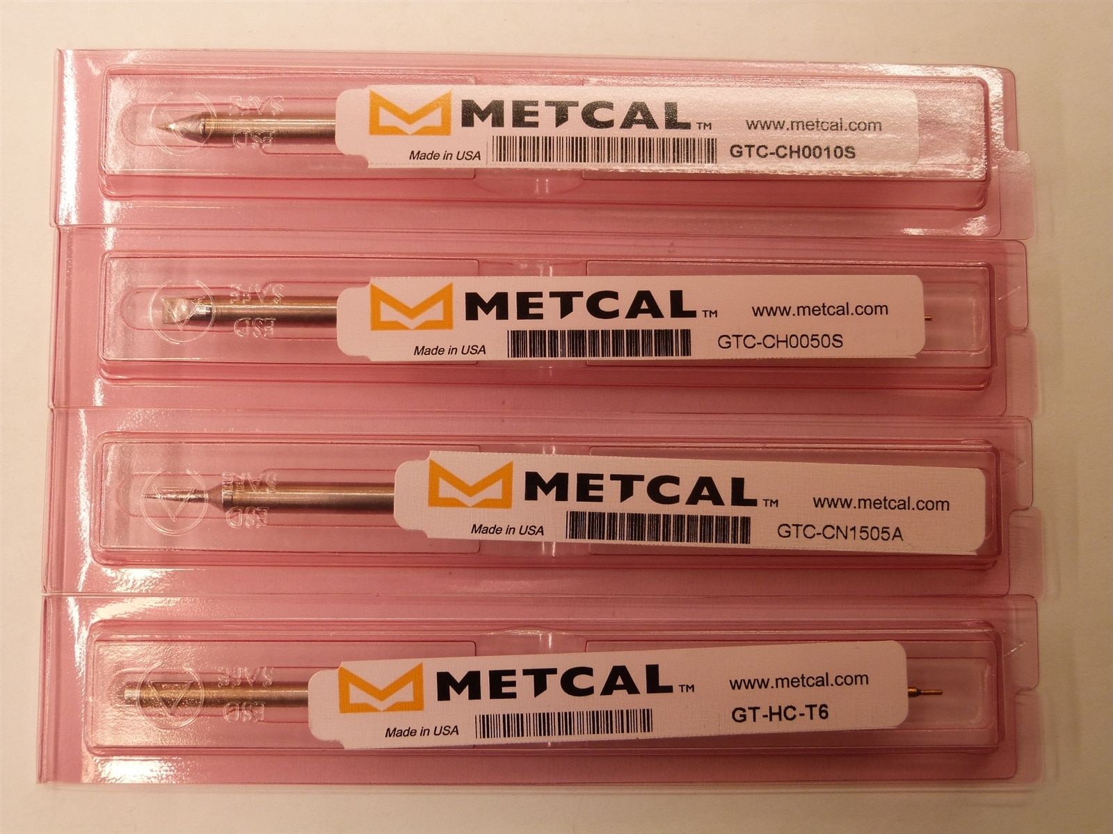
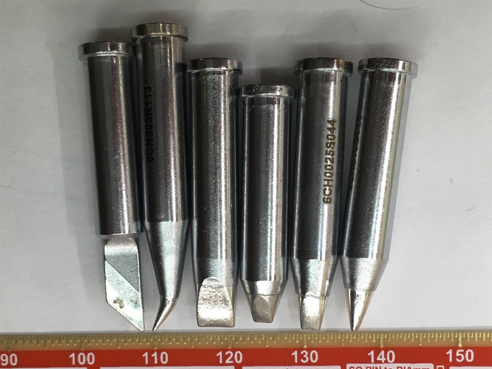
The set came with 3 stand-alone cartridges and a special cartridge heater with 6 extra tips. They get assembled slightly different, the stand-alone cartridges go straight into the hand-piece, using the short plastic adapter piece. The tips are assembled with the long metal-sleeve adapter and the cartridge heater. The tips have a big advantage as only the inexpensive tip is going to be replaced and the cartridge heater stays in place. This is a clever solution to make the station more versatile and lower cost for replacement material. I am really excited to see how the 2 different options perform.
For the cartridges, there are:

The tips are:

A text-less quick start guide was part of the system, but no full manual was available on the website for download at the time of installation.
The cartridges are fitted into the handpiece just like all other Metcal systems. Pull out the old one and replace it with a different one. It is a matter of seconds to change and keep working. The cartridge heater + tip go together very similar to a standard ceramic heater handheld. The metal sleeve needs to be unscrewed and placed somewhere on a non-melting surface, change the tip and screw everything back together. Tolerances on the Metcal system are really good, everything goes together very tightly and I expect very good heat transfer and performance out of the system. A very useful detail is the plastic grip of the screw sleeve, handling with fingers without the use of pliers/a small wrench is possible.
The handpiece sits nicely in its cradle, picking it up can be done ergonomically with a sliding or lifting motion. There are holes for 8 tips/cartridges, so almost everything can be stored securely within reach. The only piece I have found no good storing place for, is the unused screw sleeve.
The handpiece work-stand has a well for the sponge in the front. It is always very satisfying to wet the compressed sponge for the 1st time and see it rise to its useful size. Tucked under the handpiece cradle is an area with a silicone pouch that keeps the brass sponge pad. This is a very intelligent solution to keep the brass pad accessible and protected. There is a spring loaded mechanical button at the back of the stand, which was a mystery at first. After some playtime I found out that the base with the wet sponge and the handpiece cradle are able to separate through that button. I don’t see a use case for this option, but it looks like an interesting feature. If that spring loaded button would be a little smaller in diameter and slightly longer, it could serve as a holder for the unused cartridge sleeve. A silicone pad is attached to the hand-piece cable, useful to grab a hot tip and have it rest there until cool-down.
The hand-piece cable plugs into the front of the GT-120 station. At the back is the plug for the power brick, a female USB-A connection and the on-off switch. I like to have power switches at the front of devices for better accessibility, but it is at the top of the housing and very good to reach. Apparently Metcal changed their industrial design from plain black to a dark-orange coloured housing, which I think is a very good choice. It looks appealing to the eye and has good contrast to the blue display. The station is powered by a separate brick, which is un-usual for soldering stations but keeps the workbench clean, as the station itself has a small and compact footprint. The brick is 48 V 2.5 A, so there is 120 W available to power the station and heat the tips. The USB port at the back enables firmware updates or powering accessories. This is a nice extra; I will see how often I am going to use it. And this is my 1st soldering station that requires potentially a firmware update. On the product page (https://store.metcal.com/en-us/shop/soldering-desoldering/soldering-desoldering-systems/gt-series/GT120-HP-T6) is no link to a new firmware version, so I am probably not able to explore an update procedure.
Finally it is time to turn the Metcal GT120 on for the 1st time. Boot time ( I still can’t believe I am talking about boot time on a soldering iron ) is about 1 second and then it starts heating up immediately. The rubber buttons have a solid feeling and an astonishing well defined pressure point, not mushy at all. The start screen shows firmware version 0.00.96, so I would expect an update to a production version 1.00.00 in the future.
The cartridges are chip-coded and the type is displayed in the screen, apparently the power profiles are optimized for specific types.

The display is very legible with white text on blue backlight but has a narrow viewing angle for maximum contrast. The menu structure is very straight forward. It has entries for temperature, system and energy management. Temperature settings are for the manual range and 3 presets. The system menu has options for language, an ‘admin password’, brightness and a temp offset. Energy management configures the standby timer and temperature and the sleep timer. The only thing I could not figure out without a full product manual, is how the 3 temperature presets are functioning. And I did not want to play around with the lock/password settings before the end of my experiments to not disable my unit. J Time warp comment: through my fellow’s reviews, I learnt that the quick start guide on the website is more comprehensive than the printed version in the box and the 3 preset temperatures are only active when the admin mode is activated.
The system is dimming the screen when is goes to standby and cooling down the tip to the set standby temperature. I have set it to 150 °C, which is the minimum and it is reporting 2-6 % of power demand to hold it in this state. The unit going to sleep dims the screen even more and powers down the tip heating completely. Here is the measured power draw, but the trusted Kill-A-Watt is known to not be too accurate a low power levels:
|
Status |
Power [W] |
|
Heating Max |
100 |
|
Heating at 200 °C ( 6 % power display) |
4.2 - 5.2 |
|
Heating at 300 °C (10 % power display) |
5.8 - 10.5 |
|
Heating at 450 °C (20 % power display) |
10.9 - 15.6 |
|
Standby @ 150 °C (2 - 5 % power display) |
3.3 - 6.3 |
|
Sleep |
0.8 - 1.2 |
The Metcal GT soldering system is opening up a new category as it is the first adjustable temperature station with inductive heating technology. I just picked a few similar priced models on the market as a highly subjective comparison.
|
System |
Price *) |
Power |
Temperature Range |
Heat system |
|
Metcal GT120 |
USD 545.- |
120 W |
150 – 450 °C |
inductive |
|
Metcal GT90 |
USD 469.- |
90 W |
150 – 450 °C |
inductive |
|
JBC CDB |
USD 495.- |
130W |
90 – 450 °C |
resistive |
|
JBC CDS |
USD 495.- |
40 W |
90 – 450 °C |
resistive |
|
Weller WT1010 |
USD 462.- |
95W |
50 – 550 °C |
resistive |
|
Hakko FX-951 |
USD 270.- |
75W |
200 – 450 °C |
resistive |
*) all prices from the manufacturer’s homepage (extra tips not included), street prices may vary.
I am not going to compare or comment on any performance parameters. Everybody has their preferred soldering iron and style and this roadtest is strictly about the Metcal GT120.
The hand piece has a soft silicone rubber area where the fingers are resting and has a pleasant feel on the skin. The complete hand piece is a little back heavy, when holding at the very front of the grip area. This is because of the relatively massive cable between base station and hand piece. With this grip position the tip of the iron tends to swing up easily, which is uncommon for me not being used to this iron. Distance from finger to iron tip is ~42mm, which is very close and gives excellent control over fine movements. The balance gets even only when I hold the hand piece behind the soft rubber grip. The distance finger to tip is then ~105mm, which is very long and the iron is not as good to control. Over time I do prefer the shorter distance and better control and got used to the different balance.
When a cartridge gets taken out during operation, the station goes into error mode “CARTRIDGE OPEN” which is fine and expected. Replacing the same or a different cartridge does not clear the error, but stays in this mode until the unit gets power cycled. The Metcal MX-500 with the fixed temperature cartridges at my workplace did heat up again flawlessly when pulling and re-inserting the tip during operation.
There is an interesting effect, when the system is in stand-by or sleep mode. Touching the cable to the hand-piece is enough to wake up the iron, so the capacitive (presumed) sensing circuit is very sensitive. This is a good setting, I have the iron wake up more often or better rather than not waking up when I pick up the handle.
As mentioned before, I do like the feel of the buttons to set the temperature. What could use some improvement is the ‘acceleration’ of the temperature change when I press and hold a button. The initial speed of change is OK, but after some ~25 degrees the change speeds up to a rate that makes it really difficult to stop at the desired temperature. I would prefer a slower rate and hold the button a little longer to reach the new temperature in one pass instead of multiple up down approaches.
I’m not a big fan of the 7 segment number representation in the display. Don’t mis-understand me, they are perfectly readable, I just think there could have been a better choice of font for a pixel display. They could even be ~50% larger for better read from the corner of one’s eye. Also the power display numbers being left aligned is an odd design choice. It just looks wrong when the number jumps to the left when changing from ’10 %’ to ‘9 %’. Sometimes life does not get easier, when you have worked together as an Engineer with an Industrial Designer, fun but very controversial and eye-opening on both sides. Form follows function follows form!?
With the very accurate temperature setting, I am exploring melting temperatures of my available solder types, which are listed in the following table.
|
Solder |
Type |
Melting point |
Tested Melting Temperature |
|
CHIPQUIK #SMDSWLF.020 |
Lead free solder |
217-220 °C |
210 °C |
|
Multicore MM00992 |
Leaded solder |
190 °C |
180 °C |
|
MG Chemical T3 |
Low temp paste |
138 °C |
150 °C |
|
CHIPQUIK NC191SNL15 |
Lead free paste |
217-220 °C |
220 °C |
I have lead and lead-free solder and lead-free and low temperature paste available. For my setup, I am using a ceramic tile as a base, which has a very low heat conduction to not sink any temperature away from the tip. The soldering tip of choice is the 5mm chisel cartridge to maximize the contact area between the iron and the solder sample. Thorough tip cleaning is done between tests to not contaminate the samples with other materials, e.g. adding lead to the low temperature solder would reduce the melting point even further. This could be important went building circuits, that dissipate a lot of heat, with low temp solder. A high power application could start to soften or even melt solder connections at critical components and introduce unwanted catastrophic failures. I have 2 rules around low temperature solder.
As shown in the short video, lead solder (60Sn/40Pb) is already melting at 180 °C. Lead-free solder (96.5Sn/3Ag/0.5Cu) is starting to melt at ~210 °C. Lead free solder paste (same composition) has an interesting effect of evaporating the flux solution and hardening the paste first and then starting to liquefy the remaining solder material. Low temperature paste is melting easily at 150 °C, which is the lowest temp setting for the Metcal GT120.
Here a little video demonstrating the different types of solder melting.
Solder melting test on Youtube
Holiday side note: Candle temperature is measured at >1000 °C, as it easily melts lead-free solder!? Because it is Christmas time while I am writing this.
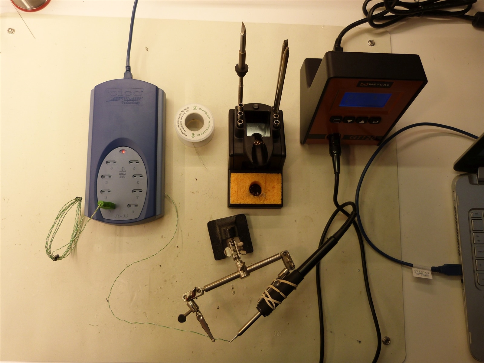
I always wanted to fuse a thermocouple probe to a soldering iron tip and now I have the opportunity to do exactly that and explore the accuracy of the GT120. As a proud owner of a PicoTech TC-08 (thanks to a previous road test ) data logger, this is the perfect device to record temperatures for this experiment. I am using a type K thermocouple probe. Type K thermocouples have a general temperature range of -200 to +1260 °C (-326 to +2300 °F), however there are some caveats to this. If used for temperatures below 0°C special material is needed in order to meet the specified accuracies. Also, Special Limits of Error are not specified for temperatures below 0°C. The ultimate suggested upper temperature limits for Type K are based on the size of the conductor used [1]. My probe has a #30 AWG wire, so the maximum temperature is 760 °C/1400 °F, which is plenty for my application with a maximum temperature of the METCAL GT120 at 450 °C.
With the hand piece and the thermocouple wire clipped into helping hands, it is easy to place the probe onto the tip and improve the heat transfer with a bit of lead free solder. The solder is not really wetting the thermocouple wires, but flux residue makes a good enough adhesion layer that the probe sticks to the soldering iron tip when the temperature is cold enough to not melt the solder. For reference, a slide show of all tips under test.
| {gallery:width=800,height=600}Tip Temperature Closeups |
|---|
|
0.5 mm conical bent tip |
|
0.5 mm conical bent tip closeup |
|
0.5 mm conical cartridge |
|
1mm Chisel Cartridge |
|
1mm Chisel Cartridge closeup |
|
1mm Chisel Tip |
|
1mm Chisel Tip closeup |
|
2.5mm Chisel Tip |
|
2.5mm Chisel Tip closeup |
|
2.5mm long Chisel Tip |
|
2.5mm long Chisel Tip closeup |
|
5mm Chisel Cartridge |
|
5mm Chisel Cartridge closeup |
|
5mm Chisel Tip |
|
5mm Chisel Tip closeup |
|
Knife Tip |
|
Knife Tip closeup |
I did a crude test with shielding the measurement area by cupping my hand above it and the temperature measurement started to rise noticeably. I did not add this to my results as it was too un-controlled to be accurately repeatable. A small thermally isolated test chamber would give absolute temperatures even closer to the set temperature. All experiments are happening in an open environment, so there is some degree of convection cooling happening and skewing the results to slightly lower temperatures and slower times.
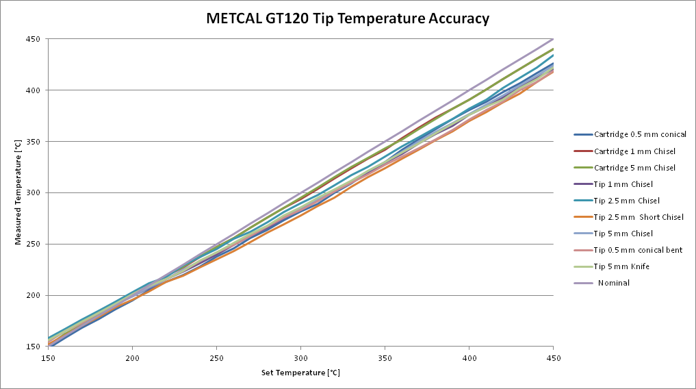
Temperature change is very linear for all tips from 150 °C minimum to 450 °C maximum temperature. Deviation from the set point is overall between 5% and -8%, without any added offset. This already is very good. It seems to be calibrated to 200 °C, which shows a deviation of only ±2% across all tips. Setting an offset temperature in the iron’s configuration can reach this excellent accuracy at any arbitrary temperature.

The next parameter I wanted to test is the heat-up and cool-down cycles of different tips. It is the same experiment setup with the thermocouple fixed at the respective tip. For practicality, I start the test be turning on the iron from ambient temperature, set to 450 °C. Standby timeout is set to 1 minute and as soon as the unit starts cooling when entering standby mode, I turn if off again, just to be sure to not trigger a wake up event mess up my measurement.
The heat up cycle graphs over time show nicely the different performance of the 3 groups; the cartridges heating up quickest; lower thermal mass tips winning the race. The Metcal replaceable tips are very even in heat up time, with the 2.5 mm chisel tip being the outlier, my guess would be a better thermal connection to the sensor. For reference I approximated the test with my Hakko FX-888, which has a manual temperature dial, which was set to 450 °C and then turned the unit on to start the heat cycle. A clear difference in performance to the resistive heating technology is visible.

Cool down cycles from max temperature to ambient are quite even across the board, again smaller tips being slightly faster and the Hakko with the much larger mass lagging behind.

Lastly, I want to show a working temperature heat up and cool down cycle. For good comparison I am choosing the 1 mm chisel because it is available to me as cartridge and tip. For temperature limits I am picking 150 °C as lowest possible standby temperature and 320 °C as operational temperature, which is a setting I like to use for leaded solder. Measurement resolution is 100 msec as I was expecting a very fast heat-up cycle for the superior inductive heating technology. For ease of test procedure and data capture I recorded a full cool down – heat up cycle and picked the relevant time periods from the data file. I always added 2 seconds at the front of the graphs to visualize the actual start of temperature change, but used the first significant change for the absolute time duration measurement. Again, the bumps at ~210 °C shall be ignored as artifacts of the temperature logger.
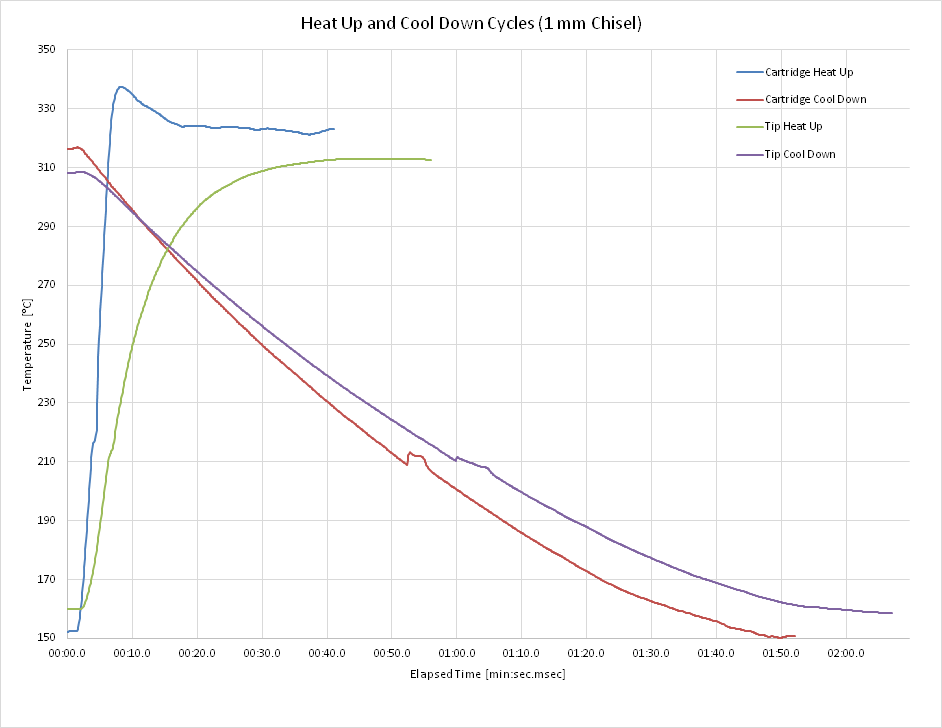
And the results are not surprising as the cartridge heats up much faster than the tip. There is a significant overshoot of the target temperature with the cartridge, the tip has a more damped approach. The slower tip heat-up cycle is very much expected, as the temperature gradient needs to cover one more gap between the universal tip cartridge and the actual tip with a significant thermal resistance.
Also the cool down cycle is faster, but not as important for performance and usability.
Here are my measured times:
|
Type |
Cartridge |
Tip |
|
|
|
Heat up |
4.5 sec |
19.9 sec (reach 300 °C) |
|
|
|
Cool down (to 160 °C) |
1:31.4 min |
1:55.9 min |
|
|
A ~4 second startup time for the cartridge is perfect to get the iron ready when picking it up from its cradle, taking a deep breath to focus on the task and start soldering immediately. Also the tip heating time is in a range to not slow down the work cycle significantly, especially when the cooling tip did not reach ambient temperature yet, but heating back up from some intermediate value. As a side note, standby also works when in menu mode, the unit powers down even when the menu is visible on screen.
Finally, heat up performances between different cartridges might be an interesting follow-up measurement to see the impact of the different thermal masses.
And as a soldering iron is ultimately meant for productive soldering, I am going to show off a little project, which highlights the capabilities of the unit when guided by an experienced hand.
I have samples of the SiTime SiT3521 ‘1 to 340 MHz Elite Platform I2C/SPI Programmable Oscillator’ sitting on my desk and had no time and real project to use them on an actual PCB. So I am going to mount it on a breadboard, which sufficient support circuitry show it is functioning. The device comes in a handy 10-Lead QFN, 5.0 x 3.2 mm package with pad distance of 1 mm and 1.27 mm dimensions. No problem for hand soldering, right!? I guess I am doing this one dead bug style. Pro tip: Always, ALWAYS mark pin 1, as everything is mirrored when working dead bug style. The planned circuit is like this, with a single 100 Ω resistor as output termination.
For the tools selection, I am going to use the 1mm chisel cartridge for TH stuff (320 °C setting) and the 0.5mm conical cartridge for magnet wires (350 – 450 °C setting to melt the enamel) and SMD components 0603 100 nF cap, 1206 10 uF cap, (350 °C setting).
As this is a roadtest about soldering, here is another little soldering tip: First, tack the magnet wire to the through hole pin, because it has a much bigger heat sink capability, that the joint does not liquefy when soldering the other end of the short wire. The other way round would be more likely to un-solder the wire from the chip pad and you have to start over again.


To make life easier, I am holding the chip in place with double sided sticky tape with the base board being 0.1” proto board. Single sided is sufficient here, as the pin header is mounted on the opposite side and no other components are going to live there. The proto board should be wide enough (0.3”) to bridge the center of a regular prototyping board. Melting some solder on all the pads of the chip first, makes life easier when attaching the wires. Did I mention to mark pin 1? After a few wires are attached the chip is going to stay in place and everything can be cleaned with IPA without fear that the adhesive would lose it stickiness. Here is a nice shot with the 0.5 mm conical tip as a size reference.

The center pad is recommended to connect to GND only for heat dissipation, so I can perfectly use it as a makeshift trace to get the ideal position for the 0603 size 100 nF capacitor. The larger one is a 1206 10 uF ceramic capacitor.

Now the board-mounted chip is read for some protoboard action.
Mounting the experimental board with the required connections on a prototype board looks like this.
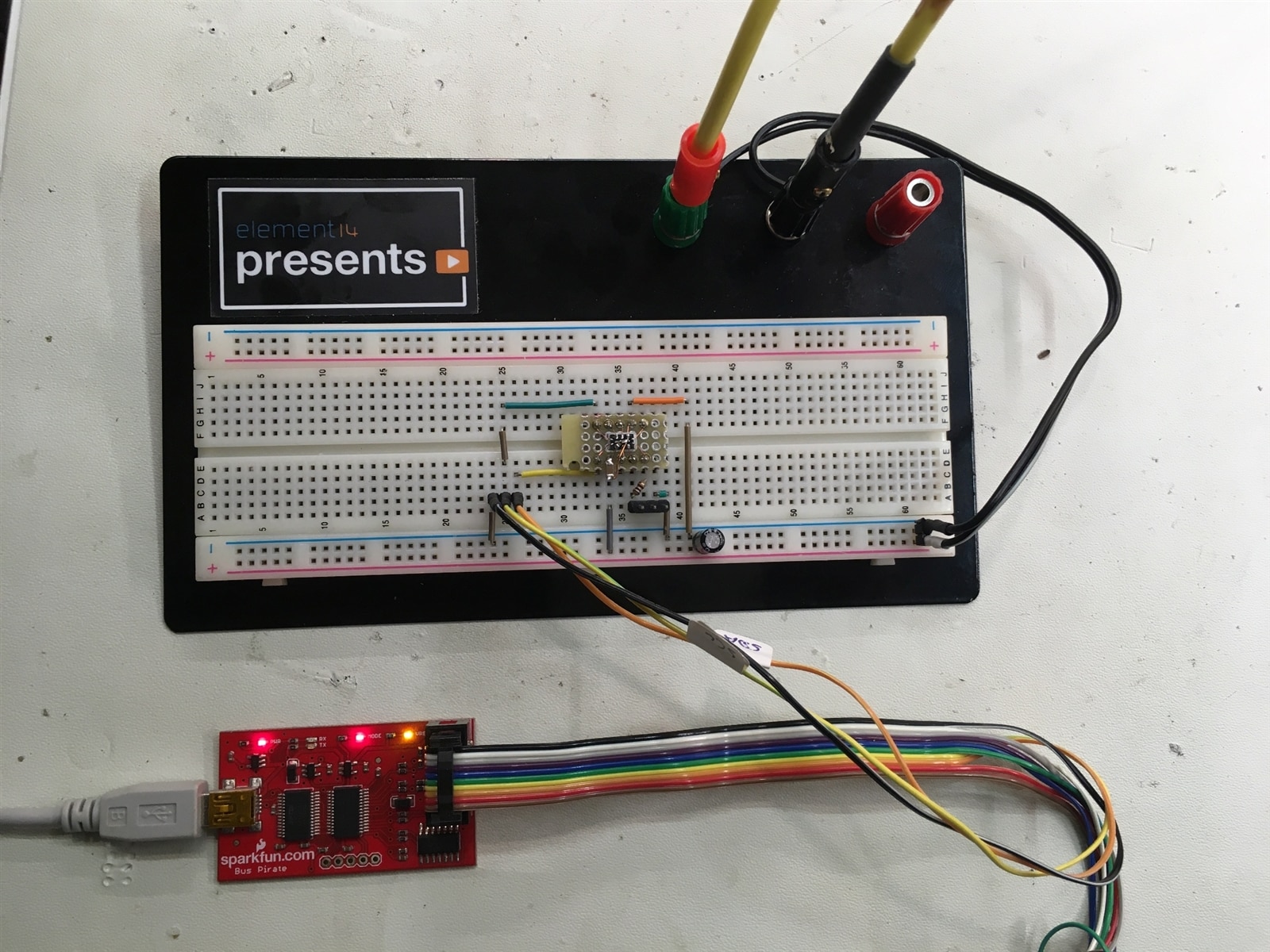
A bus scan with my trusted Bus Pirate shows the device at the expected address.
I2C>m
…
I2C>4
…
I2C>2
…
I2C>(1)
Searching I2C address space. Found devices at:
0xD4(0x6A W) 0xD5(0x6A R)
These are the correct I2C addresses for write and read operations to the chip and prove correct operation for now.
Programming the SiT3521 shall not be part of this road-test, and deserves a separate write-up.
The METCAL GT120 is an excellent soldering iron, bringing inductive heating into the world of temperature adjustable stations. Everything about the system from the handpiece to operation is very well thought out and perfectly usable. The temperature range from 150 °C to 450 °C is the most one would ever need for soldering. 400 °C is also plenty temperature to heat up your coffee (don’t try this at home!). The documentation and user manual is lacking a little, but then it is not very hard to figure out how to put a few connectors together and navigate the menus. For now I will keep both, my current Hakko FX888 and the new METCAL GT120, on the workbench to find out how quick the new one will replace the old workhorse.
Long term durability and the wear of the thread of the 2 plastic thumb nuts to hold the cartridge/tip in place, could not be tested during the road test and depends a lot on the frequency of changes between styles and tips. It would be nice to see them as a buyable single item. The advantage of the cheaper replaceable tips might be offset by the fact that every tip change requires the nut to be threaded in and out and might wear much quicker than the one for the cartridges which stays in place when changing this style of front end.
I am definitely going to shop for at least one more tip, as my favourite style is the pencil tip with the concave solder reservoir for drag soldering any type of IC. At METCAL they are called hoof tip and possible candidates are:
GT6-HF6015V Hoof Tip (GT6), Concave, (Bevel/L)60°x3.1mm, (ØxL)1.5mmx12.0mm
GTC-HF6015V Hoof Rework Cartridge (GTC), Concave, (Bevel/L)60°x3.1mm, (ØxL)1.5mmx12.0mm
Which one is depending on my budget, as the cartridges are clearly a premium item.
It is going to be interesting how my e14 colleges are going to report about the GT90 and to extract any significant differences between the GT120 and GT90.
PS: I had a closer look at the USB interface and how much power it can deliver for device charging. See the extra blog post for details.
Top Comments
Nice review ... interesting to see the temperature overshoot on some of the tips. Suggests to me that perhaps the internal PID control isn't as tight as it could otherwise be. I suppose that's what the…