RoadTest: Panasonic Laser PM2.5 (Dust/Smoke) Sensor w/ MCU - Industrial Sensing
Author: karthikrajagopal
Creation date:
Evaluation Type: Independent Products
Did you receive all parts the manufacturer stated would be included in the package?: True
What other parts do you consider comparable to this product?: PMS5003 Sensor from Adafruit , PMSA003I Sensor from Adafruit
What were the biggest problems encountered?: Register value to actual concentration value conversion was not clearly mentioned in the datasheet.
Detailed Review:
Introduction:
This is a Road-Test to review the Panasonic - Particulate Matter Sensor. An overview of the sensor’s capabilities and ways to interface will be covered.
Particulate matter sensors are used to detect the concentration of particles in air by light scattering method. The light is then analyzed to get info on particle size and count.
These sensors are used to determine the Air Quality Index (AQI) of the environment which is a measure of how clean the air around us is. They are also used to detect particles like smoke, dust and soot which are few microns in diameter.

Panasonic’s SNGCJA5 PM sensor uses the same principle of light scattering to detect particles. With the combined action of Laser diode with embedded system, the sensor outputs the mass-density value in µg/m3 .
The sensor supports both I2C and UART modes of interfacing. The detectable particle sizes are PM1.0, PM2.5 and PM10.


The sensor makes use of the GH type connector from JST for interfacing.

The sensor was much smaller than expected having a dimension of 37x37x12 (lxbxh in mm).


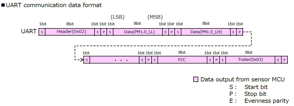
The UART interface follows a single Start bit, Stop bit, Evenness parity bit with 8 data bits. The sensor uses a 3.3V interface. This will be compatible with most of the 3.3V and all 5V logic microcontroller and won’t need any level shifters.


Start and End of the bit streams are marked by transmitting a 0x02 and 0x03 respectively. The values are updated every second (around 960ms ) and are transmitted from the sensor through a new bit stream.

The first seven bit streams had no proper data in them which underpinned the initial 8 seconds of the stabilization time in the datasheet.

The following are the output from the sensor (after stabilization).


In UART interface, only a single wire is needed which makes it a better option over I2C when we are running out of GPIOs.
Since the sensor keeps pushing new data for each second, a read can result in reading a random data from the whole stream. Header and Trailer bits can be used in such cases to identify the proper start and stop of the bit stream.
The output of the UART is limited to 2000µg/m3.
I2C interface for the sensor follows a protocol with a start, stop and repeated start condition with register and slave addresses in between.

Since the Microcontroller in the sensor follows a 3.3V logic, level shifters have to be used when interfacing with a 5V logic device. Unlike UART, I2C can output a maximum particle concentration value of 9999 µg/m3 .

Interfacing the sensor over I2C with Arduino UNO was not simple as the existing libraries do not support a repeated start condition. After modifying the code to suit the current protocol, Arduino was able to output till the Register address and also received an acknowledgement from the sensor. After performing a High to Low in SDA while SCL was high (Condition for repeated start), the code didn’t proceed and all the interfaces (both UART & I2C) were not responding to any of the following instructions in the program. So, I developed a code where all the transitions were programmed to match the I2C pattern of the sensor. Any digital pins on Arduino UNO can be used to interface with the sensor (Not limited to the dedicated I2C pins).
Circuit:

The circuit serves two purposes. First is to make logic level shifting and second is to convert the push-pull output to open drain output.
Arduino Code:
//I2C Code for PM Sensor
#define SCL 4
#define SDA 5
byte ack=1;
byte data[8];

void setup() {
  Serial.begin(115200);
  pinMode(SCL,OUTPUT);
  pinMode(SDA,OUTPUT);
  digitalWrite(SDA,HIGH);
  digitalWrite(SCL,HIGH);
  for(int j=12;j<24;j++)
  {init1(j);}
  init1(38);
}

void loop()
{

}

void init1(int addr)
{
   //START CONDITION
 digitalWrite(SDA,LOW);
 delayMicroseconds(1);
 digitalWrite(SCL,LOW);

 //SLAVE ADDRESS --> 0110011
 digitalWrite(SDA,LOW);
 clk();
 digitalWrite(SDA,HIGH);
 clk();
 clk();
 digitalWrite(SDA,LOW);
 clk();
 clk();
 digitalWrite(SDA,HIGH);
 clk();
 clk();

 //READ/WRITE
 digitalWrite(SDA,LOW);
 clk();

//Changing to input mode to read ACK
pinMode(SDA,INPUT_PULLUP);
delayMicroseconds(30);
ack = 1;
ack = digitalRead(SDA);
if(ack)
{Serial.println("Slave address Failed");while(1);}
clk();


//REGISTER ADDRESS
pinMode(SDA,OUTPUT);
for(int ii=8; ii>0;ii--)
{
float power = pow(2,ii-1);
power = power + 0.1;
int powint = power;
int m = (addr & powint)>>(ii-1);
if(m == 1)
{digitalWrite(SDA,HIGH); clk();}
else
{digitalWrite(SDA,LOW); clk();}
}

//Changing to input mode to read ACK
pinMode(SDA,INPUT_PULLUP);
delayMicroseconds(30);
ack = 1;
ack = digitalRead(SDA);
if(ack)
{Serial.println("Register address Failed");while(1);}
clk();

//REPEATED START CONDITION
pinMode(SDA,OUTPUT);
digitalWrite(SDA,HIGH);
digitalWrite(SCL,HIGH);
digitalWrite(SDA,LOW);
delayMicroseconds(1);
digitalWrite(SCL,LOW);

//SLAVE ADDRESS --> 0110011
 digitalWrite(SDA,LOW);
 clk();
 digitalWrite(SDA,HIGH);
 clk();
 clk();
 digitalWrite(SDA,LOW);
 clk();
 clk();
 digitalWrite(SDA,HIGH);
 clk();
 clk();

 //READ/WRITE
 digitalWrite(SDA,HIGH);
 clk();


//Changing to input mode to read ACK
 pinMode(SDA,INPUT_PULLUP);
 delayMicroseconds(500);
 ack = 1;
 ack = digitalRead(SDA);
 if(ack)
 {Serial.println("Read Failed");while(1);}
 clk();

//READING DATA FROM SLAVE
for(int i=0;i<8;i++)
{data[i] = digitalRead(SDA);
 clk();
 delayMicroseconds(30);
}

//NACK
pinMode(SDA,OUTPUT);
delayMicroseconds(1);
digitalWrite(SDA,HIGH);
clk();

//STOP CONDITION
digitalWrite(SDA,LOW);
digitalWrite(SCL,HIGH);
delayMicroseconds(3);
digitalWrite(SDA,HIGH);

Serial.println("End of Transmission");
byte datfinal = 0;
for(int i=0;i<8;i++)
{datfinal += data[i]<<(7-i);}
Serial.println(datfinal,DEC);
Serial.println(" ");

}


void clk()
{
  digitalWrite(SCL,HIGH);
  delayMicroseconds(3);
  digitalWrite(SCL,LOW);
  delayMicroseconds(3);
}
Waveform:

This is the I2C pattern read using logic analyzer. One set (from start to stop) took about 3.6ms.
The 1st two waveforms are the direct output from the microcontroller (5V logic) and the last two waveforms are the output of the level shifter. I read the 2nd pair to ensure the circuit worked fine.

This is the repeated start condition. All the timings were followed as mentioned in the sensor’s datasheet.


Complying with the specifications, the sensor for the test was powered with a 5V DC power supply. For all the tests, I went with a linear power supply in order to avoid issues due to switching noise. The sensor drew about 60 mA of current at 5V.
According to the above table, the sensor needed to be powered with at least 4.5V for a reliable operation. The following are the results of operating the sensor at the lowest rated voltage.

19510 -> 11000011 corresponds to an abnormal fan status.
6510 -> 01000001 corresponds to Normal status with S/W correction

At least the sensor was able to output an error status in such undervoltage condition which suffice to know the problem.
At voltages higher than 5V (around 5.3V), the sensor started to produce a high-pitched sound and the fan speed was continuously changing.
This is the short audio clip that I recorded when the sensor was operated at 5.3V. The sound was reasonably audible compared to the magnitude of sound at 5V. The change in fan speed is also clear from the audio.
Though the datasheet mentions a supply voltage of 5V ± 10%, from the test the reliable range was found to be from 4.8V to 5.2V which is 5V ± 4%.
Note: All the above supply voltage analysis were done only after completing the forthcoming tests to prevent the damage to the sensor before the main tests.
Test setup:
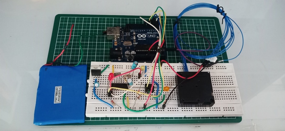
I used an Arduino UNO to read and write to the PM sensor.
For the AQI test, an external timer and an EEPROM chip was used to log data over a period of 24hrs.


The test setup was placed exposed to open air (protected from direct wind and sunlight) and the readings were recorded.
Circuit:

The above circuit is for data logging as the AQI calculation needs an average of particle concentrations over a period of 24hrs (Sampled each hour).
A pulse each of 30min duration was generated using IC 4060 based timer and the data (from the sensor) is stored in the EEPROM. I have considered 2 samples/hour instead of a sample considering deviations in values at the instant of sampling and also for accuracy.
Arduino Code:
//ACCURACY TEST
//EEPROM PINS
#define CS 3
#define CLK 4
#define DI 5
#define DO 6

//TIMER PINS
#define counter 7
#define done 8

unsigned int recvByte[32];
byte i=0;
byte ad=0;
long int PM=0;
bool prevState=0;

void setup()
{
  Serial.begin(9600, SERIAL_8E1);   //8bit, Even Parity , 1 Stop Bit
  pinMode(CS,OUTPUT);
  pinMode(CLK,OUTPUT);
  pinMode(DI,OUTPUT);
  pinMode(DO,INPUT);
  pinMode(counter,INPUT);
  pinMode(done,OUTPUT);

  digitalWrite(CS,LOW);
  digitalWrite(CLK,LOW);
  digitalWrite(DI,LOW);
  digitalWrite(done,LOW);
  delay(8000);

}

void loop() {
 start:
  if (Serial.available() > 0 && ad!=48)
  {if(i==32)
      {i=0;}
    recvByte[i] = Serial.read();
    if(i==0 && recvByte[0]!=2)
    {i=0; goto start;}
    i++;

  if(i==32 && recvByte[0]==2 && recvByte[31]==3 )
  {
    //****************************************************************PM1.0********************************************************
        Serial.print("PM_1.0: ");
    //    Serial.print(recvByte[4],BIN);
    //    Serial.print(recvByte[3],BIN);
    //    Serial.print(recvByte[2],BIN);
    //    Serial.println(recvByte[1],BIN);
        concentration(recvByte[1],recvByte[2],recvByte[3],recvByte[4]);
        Serial.println(PM);

    //****************************************************************PM2.5********************************************************
        Serial.print("PM_2.5: ");
//        Serial.print(recvByte[8],DEC);
//        Serial.print(recvByte[7],DEC);
//        Serial.print(recvByte[6],DEC);
//        Serial.println(recvByte[5],DEC);
        concentration(recvByte[5],recvByte[6],recvByte[7],recvByte[8]);
        Serial.println(PM);

    //****************************************************************PM10********************************************************

        Serial.print("PM_10: ");
    //    Serial.println(recvByte[12],BIN);
    //    Serial.println(recvByte[11],BIN);
    //    Serial.println(recvByte[10],BIN);
    //    Serial.println(recvByte[9],BIN);
        concentration(recvByte[9],recvByte[10],recvByte[11],recvByte[12]);
        Serial.println(PM);
        Serial.println("*****************");

     }


  }
   else if(ad == 48)
    {
      digitalWrite(done,HIGH);
    }
}

//**************************************************************CONCENTRATION******************************************************
void concentration(int LL,int LH,int HL,int HH)
{
PM = (LH * 255) + LL;
byte cc = digitalRead(counter);
if(cc && (cc != prevState) )
{
Enable();
Write(ad,PM);
Disable();
Read();
//Serial.println("Memory");
prevState = 1;
ad++;
}
else if(cc == 0)
{prevState =0;}
}


//****************************************************************CLOCK********************************************************
void clk()
{
digitalWrite(CLK,LOW);
delayMicroseconds(1);
digitalWrite(CLK,HIGH);
delayMicroseconds(1);
}

//****************************************************************READ********************************************************
void Read()
{
clk();
digitalWrite(CS,HIGH);
digitalWrite(DI,HIGH);
clk();clk();
digitalWrite(DI,LOW);
clk();
digitalWrite(DI,LOW);
clk();clk();clk();clk();clk();clk();  //Having CS high will print all data from the mentioned address till end..so declaring it as 000000

//Printing function
for(int ii=0; ii<64;ii++)
  {Serial.print("Data at address");
   Serial.print(ii);
   Serial.print(":");

    for(int jj=0;jj<16;jj++)
      {clk();
       byte x= digitalRead(DO);
       Serial.print(x);
      }

    Serial.println("");
  }

digitalWrite(CS,LOW);
}

//****************************************************************WRITE********************************************************
void Write(int addr, int data)
{
digitalWrite(CS,LOW);
clk();
digitalWrite(CS,HIGH);
digitalWrite(DI,HIGH);
clk();
digitalWrite(DI,LOW);
clk();
digitalWrite(DI,HIGH);
clk();

//***********ADDRESS***********

for(int ii=6; ii>0;ii--)
{
float power = pow(2,ii-1);
power = power + 0.1;
int powint = power;
int m = (addr & powint)>>(ii-1);
if(m == 1)
{digitalWrite(DI,HIGH); clk();}
else
{digitalWrite(DI,LOW); clk();}
}

//***********DATA***********

for(int ii=16; ii>0;ii--)
{
float power = pow(2,ii-1);
power = power + 0.1;
int powint = power;
int m = (data & powint)>>(ii-1);
if(m == 1)
{digitalWrite(DI,HIGH); clk();}
else
{digitalWrite(DI,LOW); clk();}
}

digitalWrite(CS,LOW);
delayMicroseconds(1);

digitalWrite(CS,HIGH);
while(!digitalRead(DO))
{Serial.println("BUSY");}
Serial.println("Done");
digitalWrite(CS,LOW);
delayMicroseconds(1);
digitalWrite(CS,HIGH);

digitalWrite(CS,LOW);
}

//****************************************************************DISABLE********************************************************
void Disable()
{
digitalWrite(CS,LOW);
clk();
digitalWrite(CS,HIGH);

digitalWrite(DI,HIGH);
clk();
digitalWrite(DI,LOW);
clk();clk();clk();clk();

clk();clk();clk();clk();  //A total of 9 clock cycles are required

digitalWrite(CS,LOW);
delayMicroseconds(1);
clk();

digitalWrite(CS,HIGH);
clk();

}

//****************************************************************ENABLE********************************************************
void Enable()
{
digitalWrite(CS,LOW);
clk();
digitalWrite(CS,HIGH);

digitalWrite(DI,HIGH);
clk();
digitalWrite(DI,LOW);
clk();clk();
digitalWrite(DI,HIGH);
clk();clk();

clk();clk();clk();clk();  //A total of 9 clock cycles are required

digitalWrite(CS,LOW);
delayMicroseconds(1);
clk();

digitalWrite(CS,HIGH);
clk();
}
Outcomes:
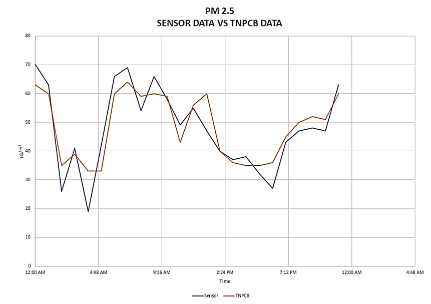
Data acquired from the test as well as from the Pollution Control Board was compared and the analysis is illustrated below.

A total of 48 values (2 samples/hr.) were obtained from the test circuit. After taking the average, the results were tabulated along with the hourly data from TNPCB.
|
|
Panasonic PM Sensor (µg/m3) |
Data from TNPCB (µg/m3) |
% Deviation |
|
|
70 |
63 |
-0.1 % |
|
|
63 |
60 |
-4.8 % |
|
|
26 |
35 |
14.3 % |
|
|
41 |
39 |
-3.2 % |
|
|
19 |
33 |
22.2 % |
|
|
42 |
33 |
-14.3 % |
|
|
66 |
60 |
-9.5 % |
|
|
69 |
64 |
-7.9 % |
|
|
54 |
59 |
7.9 % |
|
|
66 |
60 |
-9.5 % |
|
|
58 |
59 |
1.6 % |
|
|
49 |
43 |
-9.5 % |
|
|
55 |
56 |
1.6 % |
|
|
47 |
60 |
20.6 % |
|
|
40 |
40 |
0.0 % |
|
|
37 |
36 |
-1.6 % |
|
|
38 |
35 |
-4.8 % |
|
|
32 |
35 |
4.8 % |
|
|
27 |
36 |
14.3 % |
|
|
43 |
45 |
3.2 % |
|
|
47 |
50 |
4.8 % |
|
|
48 |
52 |
6.3 % |
|
|
47 |
51 |
6.3 % |
|
|
63 |
60 |
-4.8 % |
|
Average: |
47.8 |
48.5 |
|

From the graph, the output of the sensor is close to the actual concentration. The data highlighted in the table have deviation in values greater than ±10% (as mentioned in datasheet). The deviations could be due to the difference in location of test.
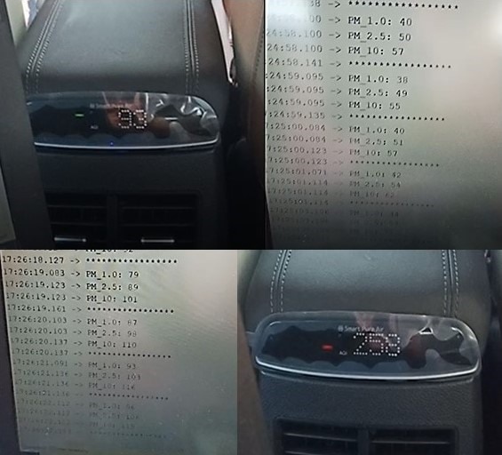
In this test, I have compared the concentration values from the sensor with that of PM sensors in the latest cars. This was done in different environments.
As the car has an in-built air filter, the reduction in concentration after activation of filter was monitored.

Arduino Code:
//AQI TEST
unsigned int recvByte[32];
byte i=0;
byte ad=0;
long int PM=0;
bool prevState=0;

void setup()
{
  Serial.begin(9600, SERIAL_8E1);   //8bit, Even Parity , 1 Stop Bit
  delay(8000);			    // 8seconds for stabilization

}

void loop() {
 start:
  if (Serial.available() > 0)
  {if(i==32)
      {i=0;}
    recvByte[i] = Serial.read();
    if(i==0 && recvByte[0]!=2)
    {i=0; goto start;}
    i++;

  if(i==32 && recvByte[0]==2 && recvByte[31]==3 )
  {
    //****************************************************************PM1.0********************************************************
        Serial.print("PM_1.0: ");
    //    Serial.print(recvByte[4],BIN);
    //    Serial.print(recvByte[3],BIN);
    //    Serial.print(recvByte[2],BIN);
    //    Serial.println(recvByte[1],BIN);
        concentration(recvByte[1],recvByte[2],recvByte[3],recvByte[4]);
        Serial.println(PM);

    //****************************************************************PM2.5********************************************************
        Serial.print("PM_2.5: ");
//        Serial.print(recvByte[8],DEC);
//        Serial.print(recvByte[7],DEC);
//        Serial.print(recvByte[6],DEC);
//        Serial.println(recvByte[5],DEC);
        concentration(recvByte[5],recvByte[6],recvByte[7],recvByte[8]);
        Serial.println(PM);

    //****************************************************************PM10********************************************************

        Serial.print("PM_10: ");
    //    Serial.println(recvByte[12],BIN);
    //    Serial.println(recvByte[11],BIN);
    //    Serial.println(recvByte[10],BIN);
    //    Serial.println(recvByte[9],BIN);
        concentration(recvByte[9],recvByte[10],recvByte[11],recvByte[12]);
        Serial.println(PM);
        Serial.println("*****************");

     }


  }

}

//**************************************************************CONCENTRATION******************************************************
void concentration(int LL,int LH,int HL,int HH)
{
PM = (LH * 255) + LL;
}
Outcomes:

AQI shown here is calculated based on PM2.5 as burnt fuel particles are mostly of size 2.5 microns.
|
AQI value from car |
Equivalent PM2.5 concentration |
PM2.5 concentration from sensor |
|
93 |
55 |
50 |
|
96 |
57 |
54 |
|
107 |
62 |
60 |
|
130 |
68 |
67 |
|
113 |
64 |
53 |
|
185 |
84 |
82 |
|
258 |
107 |
110 |
|
Concentration values after turning ON the filter |
||
|
100 |
60 |
56 |
|
56 |
33 |
32 |
|
13 |
8 |
5 |
|
2 |
2 |
3 |

Just like the previous tests, the concentration values from the sensor are almost the same as that of the actual values.
After initiating the filtering action , both outputs had a steady descend in values.
As inferred from the above tests, the sensor produced more accurate values at lower particle concentration levels than in higher particle concentration.
For the specified applications in datasheet and with the given accuracy, the sensor would best suit applications where precise values are dispensable.
TNPCB: https://www.oneindia.com/air-quality-index/chennai/
AQI Calculator: https://urbanemissions.info/tools/aqi-calculator/
Datasheet: https://www.farnell.com/datasheets/3106587.pdf
Spec sheet: https://www.mouser.in/datasheet/2/315/panasonic_08262019_Sensor_Laser_Particulate_Matter-1628325.pdf
Communication specification: https://www.mouser.com/catalog/specsheets/Panasonic_SN-GCJA5%20Data%20Sheet.pdf