RoadTest: LattePanda 3 Delta
Author: robogary
Creation date:
Evaluation Type: Independent Products
Did you receive all parts the manufacturer stated would be included in the package?: True
What other parts do you consider comparable to this product?: none
What were the biggest problems encountered?: The wifi and bluetooth antenna sockets are a bit small, took a few minutes to get them on. The unactivated Windows license was just a bit inconvenient, but fine, once I figured out what that meant. Only Digipan software seemed to have an issue with the unactivated limitation.
Detailed Review:
Latte Panda 3 Delta Road Test Goals:
INTRO: The out of box experience was effortless and amazing. AAA+++
Just plug in the peripherals and play. Its faster than my laptop. There are enough hooks and handles to be a PC and also a development tool.
You don't have permission to edit metadata of this video.
http://docs.lattepanda.com/content/3rd_delta_edition/get_started/
https://www.lattepanda.com/lattepanda-3-delta
Once the LattePanda3 Delta is booted, you’ll need to setup the WiFi and/or Ethernet just like any other PC.
After boot, the OS used 34 Gb of 64 Gb storage. I investigated SSD drives with PCIe interface to install.
The cost of a 250 Gb 1700Mb/sec read – 1100 Mb/sec Write SSD is ~ $20. A 6600 Mb/sec SSD costs $60-100+ depending on storage desired. Eventually I’ll likely install a SSD.
The 30Gb storage is fine for use as a radio PC…….after installing the needed apps and doing some video processing, storage was down to 10Gb. I used the 15 Gb free Google Drive as cloud storage for videos and a sharespace with my other PCs for this Road Test.
The user project theme of this Road Test: ham radio
To customize the LattePanda3 Delta for ham radio station support and documenting the Road Test, the desired software and drivers need loaded and tested.
The desired software and drivers were loaded progressively and tested one at a time. The starting configuration changed as lessons were learned and changes made as it went along.
Summary list of software additionally installed on LattePanda 3 Delta:
(these apps needed for documenting the road test )
Arduino 1.18 was part of installation, and other Windows 10 support Sw are there too – snip it, paint, notepad, camera, etc
The Hardware connections:
The SDR dongles did not like being on an internally powered USB 2.0 hub. The SDR dongles were plugged into the USB 2.0 when they were being used.
The homebrew Arduino interface card
The homebrew USB 2.0 pin to cable interface card
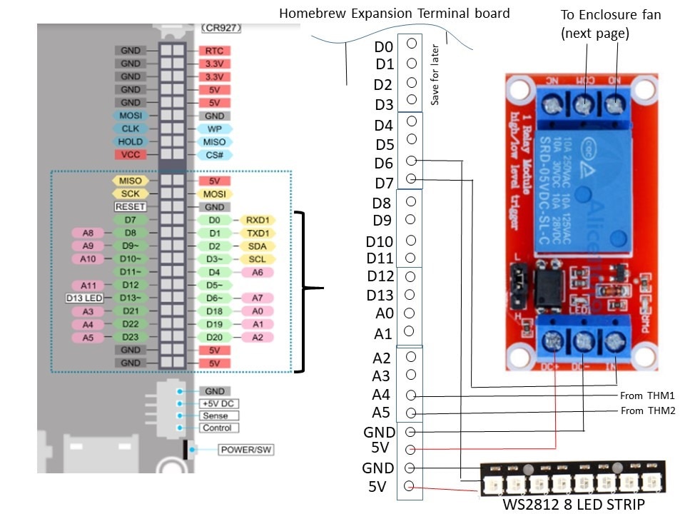
The homebrew Arduino interface card custom interface board was also built to attach the Latte Panda 3 Delta header pins for building an Arduino project for an enclosure fan control using 2 thermistors for measuring inside and outside enclosure temperature, an 8 LED WS2812 bar was used for status indicators. The details on the Arduino are later in this report.
The Road Test Video collection:
1. This is the unboxing and 1st boot up video
Unboxing and 1st Boot video
You don't have permission to edit metadata of this video.
2. Demo of an actual on air ham radio FT8 digital conversation [QSO]
FT8 digital radio contact video
You don't have permission to edit metadata of this video.
3. Demo of an actual on air ham radio PSK31 digital conversation [QSO]
PSK-31 digital conversation video link
You don't have permission to edit metadata of this video.
4. VNC Experiment: LattePanda 3 Delta VNCs into another Windows10 PC,
and then VNCs 6 more instances into qty 6 Raspberry Pis, all at the same time.
One Raspberry Pi 4 has a HQ camera with Zoom lens, which then is told to make a quick video
of me telling it to make a quick video, via the Latte Panda 3 Delta.
The RPi video is included in the clip.
VNC video link Latte Panda 3 into 6 Raspberry Pis and a W10 PC
You don't have permission to edit metadata of this video.
5. Video capture an ONLINE Jitsi meeting on L3PD
LattePanda3 Delta doing Online meetings
first clip is with Logitech C525C webcam
second clip is LattePanda3 Delta VNCed into a W10 laptop which is attending an online Jitsii meeting
LattePanda3 did all recordings and video processing
video of a Jitsi online meeting on LattePanda3 with Logictech C525 webcam
You don't have permission to edit metadata of this video.
6. SDR software defined radio
SDR in LattePanda3 Delta
You don't have permission to edit metadata of this video.
The LattePanda3 did fine, the antenna and its location needs to be better for improved reception and some operator training for a more complete demo.
7. Video streaming video –
Video streaming video
You don't have permission to edit metadata of this video.
This is a curiosity test, can a recording of a recording show the LattePanda3 Delta performance? Desktop shortcuts are created to Tubi, popcorn flix, and YouTube.
The video capture software of course blocked recording streamed copyrighted material from Tubi and Popcorn Flix.
A couple examples were recorded from YouTube, see for yourself if a demo copy of a copy and reposted , looks OK. The first example is a video I recorded and posted from a previous project, so it wasn’t HQ to start with.
8. Now for the LattePanda3 Delta on board Arduino Leonardo Project, video , photos, schematics and code
The video functional testing :
The Arduino enclosure Fan controller
You don't have permission to edit metadata of this video.
A "go kit" is a ham radio station packaged to be ready to go portable or mobile in short notice in the event of an emergency.
A "go kit" often includes the radio transceiver, power supply, and radio display. Including the LattePanda3 as a station PC mounted in the same enclosure is a logical choice with its compact size, functionality, and flexibility.
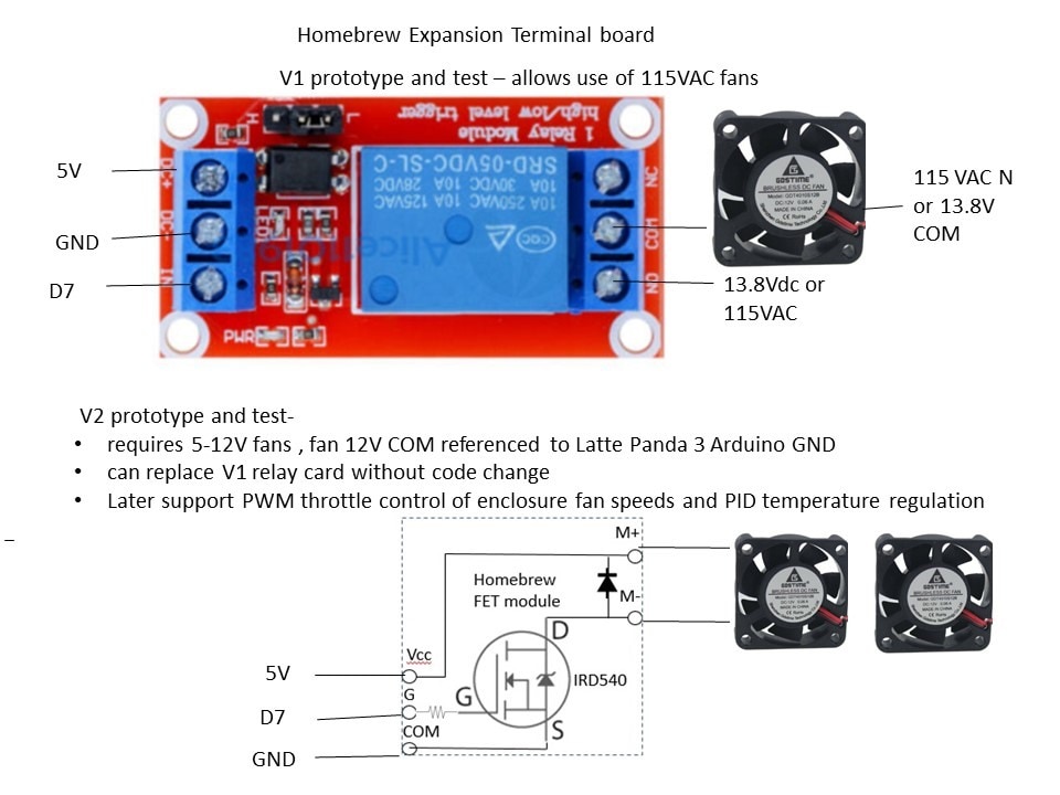
Leveraging the Arduino portion of the LattePanda3 Delta, this project provides temperature controls for the "go kit" enclosure. The Arduino Leonardo reads the outside temperature, inside enclosure temperature, compares for controlling the enclosure vent fan.
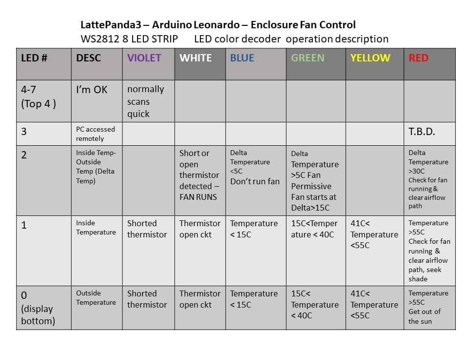
The controller also provides an LED annunciation status. LEDs were chosen as they can be seen from a distance and the colors provide intuitive feedbacks.


/ A basic everyday NeoPixel strip test program.

// NEOPIXEL BEST PRACTICES for most reliable operation:
// - Add 1000 uF CAPACITOR between NeoPixel strip's + and - connections.
// - MINIMIZE WIRING LENGTH between microcontroller board and first pixel.
// - NeoPixel strip's DATA-IN should pass through a 300-500 OHM RESISTOR.
// - AVOID connecting NeoPixels on a LIVE CIRCUIT. If you must, ALWAYS
//   connect GROUND (-) first, then +, then data.
// - When using a 3.3V microcontroller with a 5V-powered NeoPixel strip,
//   a LOGIC-LEVEL CONVERTER on the data line is STRONGLY RECOMMENDED.
// (Skipping these may work OK on your workbench but can fail in the field)

#include <Adafruit_NeoPixel.h>
#ifdef __AVR__
 #include <avr/power.h> // Required for 16 MHz Adafruit Trinket
#endif

// Which pin on the Arduino is connected to the NeoPixels?
// On a Trinket or Gemma we suggest changing this to 1:
#define LED_PIN    6

// How many NeoPixels are attached to the Arduino?
#define LED_COUNT 8

// Declare our NeoPixel strip object:
Adafruit_NeoPixel strip(LED_COUNT, LED_PIN, NEO_GRB + NEO_KHZ800);
// Argument 1 = Number of pixels in NeoPixel strip
// Argument 2 = Arduino pin number (most are valid)
// Argument 3 = Pixel type flags, add together as needed:
//   NEO_KHZ800  800 KHz bitstream (most NeoPixel products w/WS2812 LEDs)
//   NEO_KHZ400  400 KHz (classic 'v1' (not v2) FLORA pixels, WS2811 drivers)
//   NEO_GRB     Pixels are wired for GRB bitstream (most NeoPixel products)
//   NEO_RGB     Pixels are wired for RGB bitstream (v1 FLORA pixels, not v2)
//   NEO_RGBW    Pixels are wired for RGBW bitstream (NeoPixel RGBW products)

Adafruit_NeoPixel pixels(8, 6, NEO_GRB + NEO_KHZ800);

// setup() function -- runs once at startup --------------------------------

float OutsideTempCnts=0;
float InsideTempCnts=0;
int OutsideTempDegC=0;
int InsideTempDegC=0;
int x=4; // setups up 1st LED in bar to sequence
int INC=HIGH;
int OutsideAirThermistorFail=false;
int InsideAirThermistorFail=false;
int TurnOnFanPerm=true;
int TurnOnFan=false;

float THMST1_R_M; // THMST1_R value div 1000
float THMST2_R_M; //THMST2_Rvalue div 1000
float THMST1_R;
float THMST2_R;
float scratch1=0.0;
float scratch1A;
float scratch1B;
float scratch1C;
float scratch2=0.0;
float scratch2A;
float scratch2B;
float scratch2C;


float OutsideAirTemperature=0;
float InsideAirTemperature=0;
float OutsideInsideAirDelta=0;
float One_Over_Tzero = (1/298.15);
float One_OverBvalue = (1/3500.00);
float DeltaAirTemp =0;


void setup() {
  // These lines are specifically to support the Adafruit Trinket 5V 16 MHz.
  // Any other board, you can remove this part (but no harm leaving it):
#if defined(__AVR_ATtiny85__) && (F_CPU == 16000000)
  clock_prescale_set(clock_div_1);
#endif
  // END of Trinket-specific code.

  strip.begin();           // INITIALIZE NeoPixel strip object (REQUIRED)
  strip.show();            // Turn OFF all pixels ASAP
  strip.setBrightness(25); // Set BRIGHTNESS to about 1/5 (max = 255)

// SETUP FAN CONTROL IO ///////
pinMode(A5, INPUT);    // thermistor 2 inside enclosure
pinMode(A4, INPUT);    // thermistor 1 outside enclosure
pinMode(13, OUTPUT);    // sets the digital pin 13 as output
pinMode(7, OUTPUT);    // sets the digital pin 7 for relay put to turn on fan

Serial.begin(9600);
pixels.clear(); // Set all pixel colors to 'off'
}


// loop() function -- runs repeatedly as long as board is on ---------------

void loop() {

// also reference https://learn.adafruit.com/thermistor/using-a-thermistor


OutsideTempCnts=analogRead(A4);
InsideTempCnts=analogRead(A5);

////thermistor resistance calcs
    THMST1_R_M= (1023)/(OutsideTempCnts);
    THMST2_R_M= (((1023)/(InsideTempCnts)));
    THMST1_R =(THMST1_R_M*6000)-6000;
    THMST2_R =(THMST2_R_M *6000)-6000;

//// thermnistor temperature calculated by thermistor resistance,
    scratch1= log(THMST1_R/2000);  /// In Arduinoese ln is written as log
    scratch1A =One_OverBvalue*scratch1;
    scratch1B = (One_Over_Tzero)+(scratch1A);
    scratch1C= (1/scratch1B);
    OutsideAirTemperature=(scratch1C-273.15);

    scratch2= log(THMST2_R/2000);  /// In Arduinoese ln is written as log
    scratch2A =One_OverBvalue*scratch2;
    scratch2B = (One_Over_Tzero)+(scratch2A);
    scratch2C= (1/scratch2B);
    InsideAirTemperature=(scratch2C-273.15);

 //   scratch2= ((1/298.15)+(1/3500)*log(THMST2_R/2000));  /// In Arduinoese ln is written as log
//    InsideAirTemperature=((1/scratch2)-273.15);

/////////// debugging data print
     //  Serial.print("OusideTempCnts=");
      // Serial.println(OutsideTempCnts);
      // Serial.print("THMST1_R_M=");
      // Serial.println(THMST1_R_M,4);

      // Serial.print("OutsideThermistor ohms=");
      // Serial.println(THMST1_R,4);
       Serial.print("Outside Temperature=");
       Serial.println(OutsideAirTemperature);
      // delay(1000);
       Serial.print("InsideTempCnts=");
       Serial.println(InsideTempCnts);
   //   Serial.print("InsideTHMS ohms=");
   //   Serial.println(THMST2_R,4);
      Serial.print("Inside Temperature=");
       Serial.println(InsideAirTemperature);
       //   delay(1000);


//////////// indication LEDS on WS2812 bar ////////
// LED 0 = Outside Air thermistor
// LED1 = Inside Air thermistor
//LED 2 = Delta Air Temp Outside Temp - Outside Temp
// LED 3 later use VNC detected
// LED4-7 meteor


/// drive LOGIC Outside air LED 0 & thermistor failure short or open ///

if ((OutsideTempCnts<50))   // thermistor is open circuit white
 { pixels.setPixelColor(0, pixels.Color(25, 25, 25));
   pixels.show();
   OutsideAirThermistorFail=true;
  }
if ((OutsideTempCnts<680)&& (OutsideTempCnts>50))   // 680 counts ~== 15C  BLUE
 { pixels.setPixelColor(0, pixels.Color(0, 0, 15));
   pixels.show();
   OutsideAirThermistorFail=false;}
if ((OutsideTempCnts>679)&& (OutsideTempCnts<880))  // 880 counts == 40C  GRN
 { pixels.setPixelColor(0, pixels.Color(0, 15, 0));
   pixels.show();
   OutsideAirThermistorFail=false;}
if ((OutsideTempCnts>879)&& (OutsideTempCnts<915))  // 918 counts == 55C   YEL
 { pixels.setPixelColor(0, pixels.Color(15, 15, 0));
   pixels.show();
   OutsideAirThermistorFail=false;}
if ((OutsideTempCnts>916)&& (OutsideTempCnts<979) ) // 879 counts == 56C   RED
 { pixels.setPixelColor(0, pixels.Color(15, 0, 0));
   pixels.show();
   OutsideAirThermistorFail=false;}

/// drive Inside Air temperature thermistor LOGIC LED 1 ///

if ((InsideTempCnts<50))   // thermistor is open circuit white
 { pixels.setPixelColor(1, pixels.Color(25, 25, 25));
   pixels.show();
   InsideAirThermistorFail=true;}
if ((InsideTempCnts<680)&& (InsideTempCnts>50))   // 680 counts ~== 15C  BLUE
 { pixels.setPixelColor(1, pixels.Color(0, 0, 15));
   pixels.show();
   InsideAirThermistorFail=false;}
if ((InsideTempCnts>679)&& (InsideTempCnts<880))  // 830 counts == 40C  GRN
 { pixels.setPixelColor(1, pixels.Color(0, 15, 0));
   pixels.show();
   InsideAirThermistorFail=false;}
if ((InsideTempCnts>881)&& (InsideTempCnts<915))  // 879 counts == 55C   YEL
 { pixels.setPixelColor(1, pixels.Color(15, 15, 0));
   pixels.show();
   InsideAirThermistorFail=false;}
if ((InsideTempCnts>915)&& (InsideTempCnts<979) ) // 879 counts == 56C   RED
 { pixels.setPixelColor(1, pixels.Color(15, 0, 0));
   pixels.show();
   InsideAirThermistorFail=false;}

// case of shorted thermocouple
//
if ((OutsideTempCnts>980))
 { pixels.setPixelColor(0, pixels.Color(25, 0, 25));
   pixels.show();
   OutsideAirThermistorFail=true;}

  if ((InsideTempCnts>980))
 { pixels.setPixelColor(1, pixels.Color(25, 0, 25));    /// white is a shorted thermistor
   pixels.show();   // Send the updated pixel colors to the hardware.)}
 InsideAirThermistorFail=true;}


/// fan control

DeltaAirTemp=InsideAirTemperature-OutsideAirTemperature;

if (DeltaAirTemp>15.0) // inside 15C higher than outside, run fan
  {(TurnOnFan=true);
  }
  else
  {(TurnOnFan=false);}

     //  Serial.print("DeltaAirTemp=");
     //  Serial.println(DeltaAirTemp,4);
     //  Serial.print("Outside Temperature=");
     //  Serial.println(OutsideAirTemperature);

///// LED 2 cntl for Delta Temp
if (DeltaAirTemp>5.000) /// Inside temp needs to be 5 degrees warmer than the outside temp before allowing turning on fan
  {(TurnOnFanPerm=true);
   pixels.setPixelColor(2, pixels.Color(0, 15, 0));  // green if Delat t is OK
  }
 else
    {(TurnOnFanPerm=false);
   pixels.setPixelColor(2, pixels.Color(0, 0, 15));
    }

if ((InsideAirThermistorFail==true)|| (OutsideAirThermistorFail==true))
{    pixels.setPixelColor(2, pixels.Color(15, 15, 15)); } // white  if thermistor fault

if (DeltaAirTemp>30.000) /// Inside temp needs to be 5 degrees warmer than the outside temp before allowing turning on fan
  {
   pixels.setPixelColor(2, pixels.Color(15, 0, 0));  // red if delta T is too high 30C
  }
   pixels.show();


if ((InsideTempCnts>915)|| (InsideAirThermistorFail==true)|| (OutsideAirThermistorFail==true)|| ((TurnOnFanPerm==true)&&(TurnOnFan==true)))  /// force the fan on when inside temp = 40C or a thermistor fails
  {digitalWrite(7, HIGH);
  delay(50);   //
  }
  else
    { digitalWrite(7, LOW);
    }


PingPong();

}


void PingPong ()
{     pixels.setPixelColor(x, pixels.Color(0, 0, 0));
      if (INC==true)
      { x=x+1;}
      else {(x=x-1);}

      if (x==8) {x=6; INC=false; }
      if (x==3) {x=5; INC=true;}
      pixels.setPixelColor(x, pixels.Color(5, 0, 25));
      pixels.show();   // Send the updated pixel colors to the hardware.)}
      delay(75);
}