RoadTest: Read the Reviews of the Avnet ZUBoard 1CG Development Kit
Author: Z_Gaby
Creation date:
Evaluation Type: Development Boards & Tools
Did you receive all parts the manufacturer stated would be included in the package?: True
What other parts do you consider comparable to this product?: None.
What were the biggest problems encountered?: None.
Detailed Review:
Purpose:
The purpose of this project is to demonstrate the compatibility of this board. Besides the great computational power that this board is capable of delivering, it can also be a great starting point for small projects. In this project, I will go over:
Table of Content:
Unboxing:
The package was delivered in this shape:
The main package came with three boxes inside it:
1- Avnet ZUB1CG
2- Avnet DualCam HSIO Module
3- Power supply adapter
I- Avnet ZUB1CG Box:
Content of the box:
1- Avnet ZUB1CG
2- 8Gb SD Card
3- USB-C cable for the power supply
II- Avnet DualCam HSIO Module Box
II- Power supply adapter Box:
Additional Hardware & Cables:
Required Softwares:
Brief description of the Board:
The ZU1CG device is equipped with 81K programmable logic cells and features a Dual-core Arm Cortex-A53 MPCore and Dual-core Arm Cortex-R5F MPCore processors, along with cache and on-chip memory. The board includes 1GB of ISSI LPDDR4 memory and offers non-volatile boot options using either the 256Mb ISSI QSPI Flash or a microSD card slot. Microchip PHYs enable 10/100/1000 Ethernet and USB 2.0 Host capabilities, with onboard JTAG/UART access available through a micro USB port. Clocking to the ZU1 device, the on-chip real-time clock, JTAG, and communication interfaces are provided by Microchip oscillators and ECS crystals. The board can be powered via USB-C using a Microchip controller and TDK μPOL
power modules. User interaction is facilitated through a combination of slide switches, push buttons, mono- and RGB-LEDs. Environmental data is collected through temperature and pressure sensors from STMicroelectronics. Additionally, the board exposes all four ZU+ PS GTR transceivers, 18 PS MIO, and 69 PL I/Os through three Samtec expansion connectors and one Click Board
site.
Brief description of the Mikroe-2000 Micro Click:
The MIkroE-2000 is a click board designed by MikroE to enable heart rate and SpO2 (blood oxygen saturation) monitoring. At the core of this click board is the MAX30100 sensor, a high-sensitivity optical sensor capable of accurately measuring heart rate and SpO2 levels.
The click board is designed with a standard mikroBUS socket, featuring a compact form factor with six pins for seamless integration with various development boards and microcontroller platforms.
The MAX30100 sensor on the MIkroE-2000 click board utilizes photoplethysmography (PPG) technology to measure heart rate and SpO2 levels. PPG works by emitting light from an LED into the user's skin, typically on the fingertip or wrist, and then detecting the amount of light that is absorbed or reflected by the blood vessels. This data is processed by the sensor to calculate the heart rate and SpO2 levels, which are then made available to the connected microcontroller through the I2C serial communication interface.
Most importantly is that the click board is compatible with the MikroE shield on the ZU Board 1CG.
Steps of the Project:
The project is divided into three main parts:
1- View the Projects on Vivado.
2- Building and Installing PetaLinux on a Micro SDCard.
3- Writing the code for the click board.
I- Build the Projects on Vivado:
If not already done, download and install Vivado 2022.1
Once it is done, we will start exploring and then building the project on Vivado.
1- Create a directory (wherever you desire) to clone Avnet's board definition files (BDF) and HDL repositories into:


2- Navigate to the HDL directory:

3- Source the Vivado tools to the environment and change directories into the scripts directory.

4- Use Vivado in batch mode to build the Vivado project for the target Avnet FPGA board using its TCL script.

5- A base project that provides the basic connections to the available peripherals on the board will be used. 
The project will be located in ./hdl/projects/<Avnet Board projects name>/
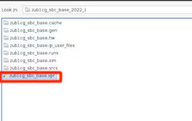
Open the Project:
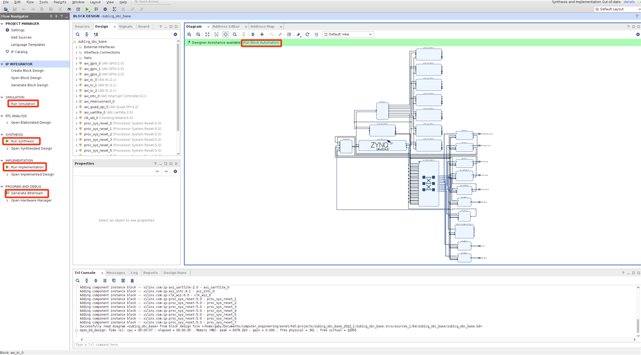
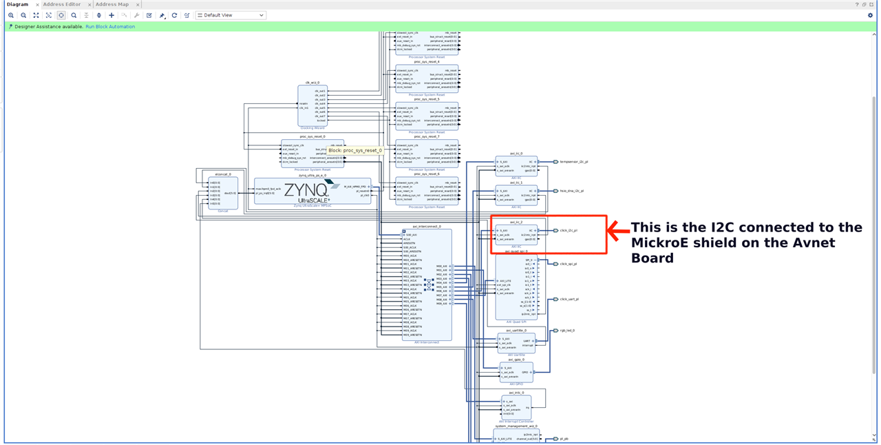
Do the "Run Block Automation", "Run Synthesis", "Run Implementation", and "Generate Bitstream"
II- Building and Installing PetaLinux on the FPGA Board:
1- Clone the PetaLinux repositories, it will be more convenient to keep them together in the same location where the BDF and HDL repositories are cloned.

2- Run the build script. I will be building the base PetaLinux project for the ZUBoard.


After the build is done, the PetaLinux projects and their respective BSP will be created in ./petalinux/projects
3- Flash the Linux image to an SD card (I used a 64 GB SD card).
The image will be created in the PetaLinux projects titled rootfs.wic located in ./petalinux/projects/images/linux
Flash an SD card with a program such as balenaEtcher and insert it into the ZUBoard.
4- Boot the board by following these next steps:
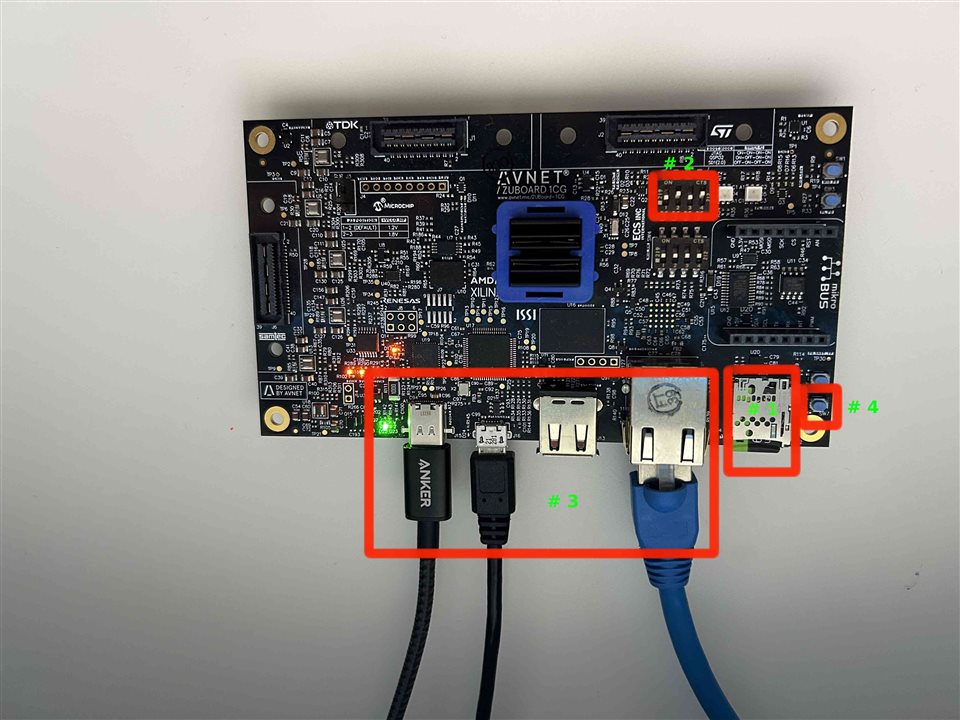
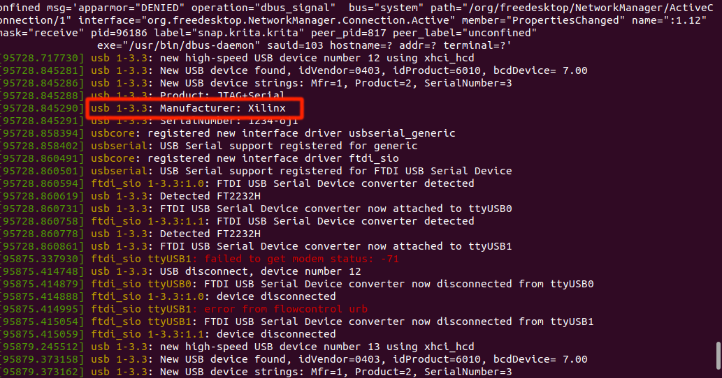
5- Disconnect the Micro USB cable open the terminal and run the following command (dmesg -w) then reconnect ZU Board 1CG USB cable to your PC to check through which USB-to-serial port is used:

FTDI-based JTAG and USB to Serial are used on ZU Board 1CG, which has 4 USB to serial ports. use the second port for the Linux terminal i.e. if /dev/ttyUSB0 is the first port, you use /dev/ttyUSB1 as the Linux terminal from ZU Board 1CG.
6- Open a new terminal and use minicom, run the following command

Note: change the number at the end respectively to the one your board is connected through.
7- You will be asked to enter the login username; type in "root" (no password is needed)
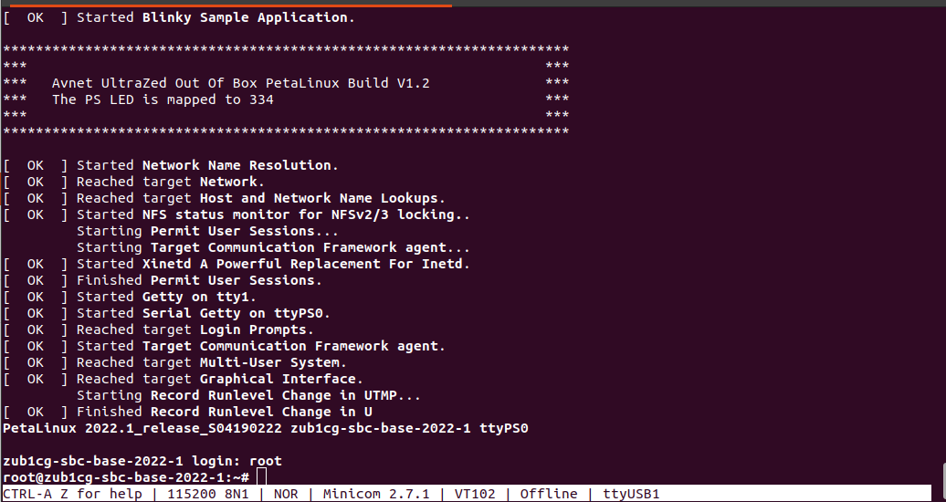
8- Check the Board's IP Address.
Type: "ifconfig"


9- Check which I2C bus is the click board using.
It should be connected through /dev/i2c-3.
Type i2cdetect -y 3; you should get the following:

Then plug in the click board to the FPGA as follows:
Type in again "i2c-detect -y 3" again and you should get the following:
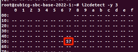
Note: If you did not get "57" on the "/dev/i2c-3" then try on the other ones.
III- Writing the code for the click board.
Now that we have the hardware ready, and we have the information needed about the click, we can start with the code.
The code will be divided into 3 sections:
The server will remain in a waiting state until a connection is established with the client. Once the client successfully binds with the server, the server will subsequently wait for the client's data request.
Upon receiving the client's connection, the server will start sending data.
Note: the server will only send the average raw values for both Red LED and IR LED.
Steps to compile and run the code on the ZUBoard:
I used "Visual Studio Code" for the following steps.
1- Lunch Visual Studio Code, and establish an SSH connection with the ZUBoard.
2- Using the VS Code create a new directory (folder) wherever you want on the board, and create 2 new files in it (max30100.h, and max30100.c).
3- Copy the "max30100.c" and "max30100.h" code that is attached here and paste it into each file you created respectively.
Note: Keep in mind that you need to change the IP address in the code (for local connection use "127.0.0.1") and the number of the i2c bus in case it was different than 3.
4- Save both files.
5- On the VS Code terminal type the following command to compile the program: gcc max30100.c -o max30100
6- From the VS Code terminal type the following command to run the program: sudo ./max30100
Now We have finished all the needed steps on the board.
On your main computer, lunch VS Code, create a new folder and paste into it the "client.c" file I have attached.
compile and run the code.
Place your finger on the sensor, and request the data you want from the server.
Conclusion:
The board caters to a diverse range of applications, spanning from beginner-level to advanced projects. Following the straightforward steps outlined above, the board can be quickly set up and made operational.
The MikroE shield on the board serves multiple functions, utilizing I2C, SPI, or UART interfaces, thereby offering a wide array of application possibilities.
Furthermore, users have the flexibility to leverage the other peripherals on the board based on their level of expertise and experience.
This board presents an engaging and stimulating environment for experimentation and exploration, making it an excellent foundation for starting various projects.